EP0476024B1 - Verbindung für glasfasern - Google Patents
Verbindung für glasfasern Download PDFInfo
- Publication number
- EP0476024B1 EP0476024B1 EP90909449A EP90909449A EP0476024B1 EP 0476024 B1 EP0476024 B1 EP 0476024B1 EP 90909449 A EP90909449 A EP 90909449A EP 90909449 A EP90909449 A EP 90909449A EP 0476024 B1 EP0476024 B1 EP 0476024B1
- Authority
- EP
- European Patent Office
- Prior art keywords
- drum
- drum holder
- slide
- connector
- plug
- Prior art date
- Legal status (The legal status is an assumption and is not a legal conclusion. Google has not performed a legal analysis and makes no representation as to the accuracy of the status listed.)
- Expired - Lifetime
Links
- 239000013307 optical fiber Substances 0.000 title claims description 24
- 230000008878 coupling Effects 0.000 claims abstract description 24
- 238000010168 coupling process Methods 0.000 claims abstract description 24
- 238000005859 coupling reaction Methods 0.000 claims abstract description 24
- 230000003287 optical effect Effects 0.000 claims abstract description 12
- 239000000969 carrier Substances 0.000 claims description 8
- 238000006073 displacement reaction Methods 0.000 claims description 2
- 239000000835 fiber Substances 0.000 description 11
- 230000000295 complement effect Effects 0.000 description 3
- 230000002093 peripheral effect Effects 0.000 description 3
- 238000005452 bending Methods 0.000 description 2
- 238000010276 construction Methods 0.000 description 2
- 230000001681 protective effect Effects 0.000 description 2
- 230000000903 blocking effect Effects 0.000 description 1
- 239000000470 constituent Substances 0.000 description 1
- 238000003780 insertion Methods 0.000 description 1
- 230000037431 insertion Effects 0.000 description 1
- 238000009434 installation Methods 0.000 description 1
- 238000004519 manufacturing process Methods 0.000 description 1
- 230000000284 resting effect Effects 0.000 description 1
- 238000000926 separation method Methods 0.000 description 1
Images


Classifications
-
- G—PHYSICS
- G02—OPTICS
- G02B—OPTICAL ELEMENTS, SYSTEMS OR APPARATUS
- G02B6/00—Light guides; Structural details of arrangements comprising light guides and other optical elements, e.g. couplings
- G02B6/24—Coupling light guides
- G02B6/36—Mechanical coupling means
- G02B6/38—Mechanical coupling means having fibre to fibre mating means
- G02B6/3807—Dismountable connectors, i.e. comprising plugs
- G02B6/3897—Connectors fixed to housings, casing, frames or circuit boards
-
- G—PHYSICS
- G02—OPTICS
- G02B—OPTICAL ELEMENTS, SYSTEMS OR APPARATUS
- G02B6/00—Light guides; Structural details of arrangements comprising light guides and other optical elements, e.g. couplings
- G02B6/24—Coupling light guides
- G02B6/36—Mechanical coupling means
- G02B6/38—Mechanical coupling means having fibre to fibre mating means
- G02B6/3807—Dismountable connectors, i.e. comprising plugs
- G02B6/381—Dismountable connectors, i.e. comprising plugs of the ferrule type, e.g. fibre ends embedded in ferrules, connecting a pair of fibres
- G02B6/3825—Dismountable connectors, i.e. comprising plugs of the ferrule type, e.g. fibre ends embedded in ferrules, connecting a pair of fibres with an intermediate part, e.g. adapter, receptacle, linking two plugs
-
- G—PHYSICS
- G02—OPTICS
- G02B—OPTICAL ELEMENTS, SYSTEMS OR APPARATUS
- G02B6/00—Light guides; Structural details of arrangements comprising light guides and other optical elements, e.g. couplings
- G02B6/24—Coupling light guides
- G02B6/36—Mechanical coupling means
- G02B6/38—Mechanical coupling means having fibre to fibre mating means
- G02B6/3807—Dismountable connectors, i.e. comprising plugs
- G02B6/3833—Details of mounting fibres in ferrules; Assembly methods; Manufacture
- G02B6/3847—Details of mounting fibres in ferrules; Assembly methods; Manufacture with means preventing fibre end damage, e.g. recessed fibre surfaces
- G02B6/3849—Details of mounting fibres in ferrules; Assembly methods; Manufacture with means preventing fibre end damage, e.g. recessed fibre surfaces using mechanical protective elements, e.g. caps, hoods, sealing membranes
-
- G—PHYSICS
- G02—OPTICS
- G02B—OPTICAL ELEMENTS, SYSTEMS OR APPARATUS
- G02B6/00—Light guides; Structural details of arrangements comprising light guides and other optical elements, e.g. couplings
- G02B6/24—Coupling light guides
- G02B6/36—Mechanical coupling means
- G02B6/38—Mechanical coupling means having fibre to fibre mating means
- G02B6/3807—Dismountable connectors, i.e. comprising plugs
- G02B6/3873—Connectors using guide surfaces for aligning ferrule ends, e.g. tubes, sleeves, V-grooves, rods, pins, balls
-
- G—PHYSICS
- G02—OPTICS
- G02B—OPTICAL ELEMENTS, SYSTEMS OR APPARATUS
- G02B6/00—Light guides; Structural details of arrangements comprising light guides and other optical elements, e.g. couplings
- G02B6/24—Coupling light guides
- G02B6/36—Mechanical coupling means
- G02B6/38—Mechanical coupling means having fibre to fibre mating means
- G02B6/3807—Dismountable connectors, i.e. comprising plugs
- G02B6/3873—Connectors using guide surfaces for aligning ferrule ends, e.g. tubes, sleeves, V-grooves, rods, pins, balls
- G02B6/3885—Multicore or multichannel optical connectors, i.e. one single ferrule containing more than one fibre, e.g. ribbon type
-
- G—PHYSICS
- G02—OPTICS
- G02B—OPTICAL ELEMENTS, SYSTEMS OR APPARATUS
- G02B6/00—Light guides; Structural details of arrangements comprising light guides and other optical elements, e.g. couplings
- G02B6/24—Coupling light guides
- G02B6/36—Mechanical coupling means
- G02B6/38—Mechanical coupling means having fibre to fibre mating means
- G02B6/3807—Dismountable connectors, i.e. comprising plugs
- G02B6/3887—Anchoring optical cables to connector housings, e.g. strain relief features
- G02B6/3888—Protection from over-extension or over-compression
-
- G—PHYSICS
- G02—OPTICS
- G02B—OPTICAL ELEMENTS, SYSTEMS OR APPARATUS
- G02B6/00—Light guides; Structural details of arrangements comprising light guides and other optical elements, e.g. couplings
- G02B6/24—Coupling light guides
- G02B6/36—Mechanical coupling means
- G02B6/38—Mechanical coupling means having fibre to fibre mating means
- G02B6/3807—Dismountable connectors, i.e. comprising plugs
- G02B6/389—Dismountable connectors, i.e. comprising plugs characterised by the method of fastening connecting plugs and sockets, e.g. screw- or nut-lock, snap-in, bayonet type
- G02B6/3891—Bayonet type
-
- G—PHYSICS
- G02—OPTICS
- G02B—OPTICAL ELEMENTS, SYSTEMS OR APPARATUS
- G02B6/00—Light guides; Structural details of arrangements comprising light guides and other optical elements, e.g. couplings
- G02B6/24—Coupling light guides
- G02B6/36—Mechanical coupling means
- G02B6/38—Mechanical coupling means having fibre to fibre mating means
- G02B6/3807—Dismountable connectors, i.e. comprising plugs
- G02B6/3887—Anchoring optical cables to connector housings, e.g. strain relief features
- G02B6/38875—Protection from bending or twisting
Definitions
- Patent EP-A-0 258 964 describes a connector which is arranged in this way.
- Fiber optic connectors have a more complicated structure than electrical connectors due to the need to align and exactly extend the fibers belonging to different cables without ever imposing excessive curvature on the fibers.
- the connector comprises, established on the end of the cables, on the one hand a barrel carrying the ends of the fibers and supported by a barrel holder which protects the fibers near their end, at a location where they are not held by the cable, and on the other hand a locking system consisting of a threaded sleeve surrounding each of the barrel holders.
- the connection is established by placing the flat end faces of the barrels in abutment one on the other on a coupling fitting after having made coincide two networks of positioning and centering pins and complementary recesses established on the two barrels so as to obtain correct alignment, then by screwing onto the coupling fitting the threaded bushings which are supported on the shoulders of the barrel holders and prevent their disjunction.
- the invention is characterized in that the means for abutting the slide and the barrel holder are arranged so that the stop is in a variable position and that it thus makes it possible to bring the slider, respectively, in a first advanced longitudinal position in which the ends of the optical fibers exit from the barrel holder from the front and in a second longitudinal position set back from the first in which the optical fibers are pulled back and bring the barrel in its housing, and in that the blocking means is intended to act when the slider is in said second recessed stop position.
- the means of connection by abutment can comprise a nut engaged by thread either on the slide, or on the barrel holder, and coming to abut on the other of these parts.
- the slider can in turn comprise as means of attachment of the carriers of the optical cable integral with the slider, a fastening system consisting of two mutually movable parts provided with conical wedging surfaces.
- Patent WO-A-84/00617 describes a connector where the barrel is mounted on the fibers before being introduced into the barrel holder. It is a different kind of connector where the barrel is inserted from the rear of the barrel holder.
- the connector according to the invention is provided in particular, to allow easy remote handling, with a handling part of essentially tubular shape which surrounds the barrel holder and is movable compared to him under certain conditions. This manipulation part is gripped by the tool and can be locked to a coupling connection via a bayonet connection.
- This connector then comprises: a part intended to be manipulated arranged around the barrel holder, movable in translation relative to the barrel holder along the plug axis, angular positioning means between the coupling connector and the barrel holder , intended to prevent the barrel holder from rotating relative to the coupling connection around the plug axis; abutment surfaces on the barrel holder and the coupling fitting along the plug axis, a connection means between the part handled and the barrel holder to prevent rotation of the manipulated part around the pin axis when the connection is not established and to allow this rotation when the connection is established, and bayonet locking means jointly disposed on the manipulated part and the coupling connector and respectively constituted by pins and grooves as well as d 'A spring disposed between the barrel holder and the manipulated part and tending to move the manipulated part along the axis of the plug away from the barrel.
- bayonet locking means jointly disposed on the manipulated part and the coupling connector and respectively constituted by pins and grooves as well as d 'A
- the plug can also comprise a tubular sheath arranged around one end of the barrel holder and mounted to slide along the longitudinal axis of the plug, as well as a spring disposed between the barrel holder and the sheath and tending to push the sheath forward, in a position where it covers the barrel.
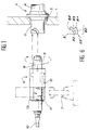
- Figures 1 and 3 in particular show how to assemble the connector.
- This comprises, fixed (or screwed) to a panel 1 or a similar support, a coupling connector 2 of cylindrical shape and having two coaxial sleeves 3 and 4 which are located on either side of the panel 1 and a central flange 5 for attaching to the panel 1.
- It also includes a cable end plug 6, carried by a remote handling tool 7 with pliers, not shown in detail, which must be engaged in one of the sleeves 3.
- the plug 6 comprises a barrel 9 supported by a barrel holder 8 which protects the fibers between the attachment of the cable and the barrel 9 to which they terminate.
- a remotely manipulable nut 10 surrounds the barrel holder 8 and an elastic ring 11, established on a groove of the barrel holder 8, prevents it from sliding along the cable 12 containing the optical fibers.
- the nut 10 is shown in more detail in FIG. 3: it comprises a rear hexagon part 13 gripped by the remote handling tool 7 and a wider front part 14, of hollow circular section and carrying on its lower face two tenons 15, an axial groove 16 and a circumferential groove 17 behind the tenons 15 and on which the rear end of the axial groove 16 opens.
- a circumferential border 18 which itself carries a keyed protrusion 19 and a finger 20 pointing forward.
- the border 18 is interrupted by two diametrically opposite notches 21 on the barrel holder 8 and only one of which appears.
- the wall of the sleeve 3 comprises two arcuate grooves 22 composed of an oblique zone 23 which extends to the rear end of the sleeve 3 and which is extended by a locking zone 24 in a rearward recess.
- a longitudinal bore 25 is also established on the wall of the sleeve 3.
- a spring 26 shown in Figures 4 and 5 is compressed between the edge 18 and a shoulder 27 established at the rear of the nut 10 on its internal face; it pushes the nut 10 resting on the elastic ring 11 so that the front of the barrel holder 8 protrudes from the nut 10.
- the first step of the connection consists in making the finger 20 penetrate into the bore 25.
- the force of the tool 7 bearing on the front part 14 then moves, by compressing the spring 26, the nut 10 along the door barrel 8 when the edge 18 has come into abutment through its front face 38 against the rear face 39 of the wall of the sleeve 3: the groove 16 slides on the key 19, the internal wall of the front part 14 slides on the edge 18 and the wall of the sleeve 3, and the tenons 15 then pass through the notches 21 and then through the arcuate grooves 22.
- the key 19 is at this moment engaged in the circumferential groove 17, that is to say that a movement of rotation of the nut 10 becomes possible without turning the barrel holder 8.
- the pins 15 thus penetrate to the bottom of the arcuate grooves 22.
- the spring 26 presses the border 18 against the rear end 39 of the wall of the sleeve 3 and maintains the pins 15 in the recessed areas 24.
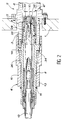
- Figure 2 and especially its enlargements formed by Figures 4 and 5, show yet other details of the connector in the connected state.
- the front end of the barrel holder 8 is thus surrounded by a barrel 28 for protecting the barrel 9.
- the sleeve 28 abuts against a separation ridge 30 established at the limit of the internal walls of the sleeves 3 and 4 and which is hollowed out at its center.
- the sheath 28 is thus held back from the front face of the barrel 9.
- the barrel 9 is designed to come into contact with the barrel of a complementary movable plug 6 'engaged in the other sleeve 4 and shown partially in phantom in a slightly retracted position.
- the barrels 9 are provided with a flat front face 31 and pins 32 paired with corresponding holes established on the other barrel. This ensures that the ends of the optical fibers 56 of the two barrels face each other. to face.
- Each barrel 9 is supported at the rear on a barrel holder 8 by an elastic washer 33 which guarantees a sufficiently flexible mounting of the barrel 9 and, in the connected state, the barrel holder 8 is supported on the nut 10 by another elastic washer 34, the elasticity of which enables the nut 10 to advance to release the tenons 15 from the locking zones 24.
- a pin 35 prevents the barrel 9 from turning relative to the barrel holder 8.
- Two screws 36 - of which only one appears in the drawing - engaged on the external surface of the barrel holder 8 protrude from the latter in two axial grooves 37 of the protective sheath 28; they serve as a stop and prevent the protective sheath 28 from being separated.
- the key 19 also makes it possible to guide the tenons 15 through the notches 21, after which the arcuate grooves 22 guide the tenons 15 to the locking zone 24. It is then enough to remove the tool 7 so that the nut 10 remains blocked and presses the edge 18 against the sleeve 3.
- This connector is special in that it allows easy installation of the optical fibers 56 in the barrel holder 8 and the barrel 9, while making it possible to minimize the bending stresses on the fibers.
- a slider 45 of tubular shape is in fact introduced from the rear into the barrel holder 8.
- the end of the optical cable 12 is engaged from the rear in the slider 45 where it is then hooked using what 'the carriers of the cable 12 are called, that is to say the sheathed filiform elements which serve to reinforce it.
- the embodiment described thus uses a central carrier 48 of relatively large section terminated by a thinned end 50, and surrounded by thinner peripheral carriers 49.
- a hooking part 51 intended to be introduced from the front into the slide 45, firstly comprises a flange 52 clamped between a shoulder 53 of the slide 45 and a clamping ring 54 threaded and screwed onto a female thread. 'before the slide 45.
- the flange 52 is provided with holes 55' intended for the passage of peripheral carriers 49 and recesses 55 intended for the passage of optical fibers 56.
- the attachment piece 51 comprises, in addition to the collar 52, a case 57 directed towards the rear and a conical sleeve 58 directed towards the front.
- the case 57 is used to crimp the central carrier 48, part of the constituent strands of which has been previously rolled up on a tube 59.
- the thinned end 50 extends inside a bore established in the axis of the sleeve.
- conical 58 of which it partially protrudes at the front and to which it is stuck there.
- the peripheral carriers 49 are then bent to come into contact with the conical sleeve 58 and held against the latter by means of a conical clamping nut 60 threaded around the conical sleeve 58 so as to wedge the clamping of the nut 60.
- optical fibers 56 are therefore introduced through the recesses 55 of the attachment piece 51 and extend into a space enveloped by the barrel holder 8. O-rings 47 are then clamped between the cable 12 and the slide 45 to prevent accidental tearing of the cable 12.
- the slide 45 is provided at the rear with a threaded surface 63 on which is threaded a cylindrical nut 64 whose outside diameter is almost equal, with only a slight play, to the diameter of an area 65 of the inner wall of the barrel holder 8 terminated by a shoulder 66 towards the front.
- the nut 64 thus displaceable on the threaded surface 63 therefore constitutes, in cooperation with the shoulder 66, a variable position stop.
- the slide 45 is gradually moved backwards and the barrel 9, pulled by the optical fibers 56 and their ends 61, sinks into the housing which has been provided at the front of the barrel holder 8 until touch the elastic washer 33.
- a retaining rim 68 is then screwed onto the barrel holder 8 to prevent the barrel from being extracted 9.
- a threaded ring 69 surrounding the cable 12 is screwed to the rear of the barrel holder 8 until to abut via the ring 72 against the rear end of the slide 45 which is then blocked.
- a sheath 70 is heat-shrunk on the cable 12 and on the grooves of the part 69.
- FIG. 6 represents a particular construction of the sleeve, referenced 3 ′, which is distinguished from the previous one by grooves 22 ′ of a shape specially adapted for remote handling tools.
- These grooves 22 ′ comprise, from the edge of the sleeve 3 ′, through which the barrel holder 8 is introduced, a rectilinear part 80 along the axis of the sleeve, a small arcuate part 81 which is substantially circumferential, a recess hollow 82, a large arcuate portion 83 substantially circumferential and a snap-in recess 84.
- the path of the tenons 15 in the grooves 22 ′ requires moving the remote handling tool 7 with a movement which is first purely axial, then with a slight rotation which places the pins 15 in the recessing hollows 82.
- the elasticity of the spring 26 keeps the plug 6 in the position reached, which makes it possible to temporarily release the remote handling tool 7 before resuming the sheet 6 to move the remote handling tool in an almost pure rotational movement and bring the pins 15 into the snap-in recesses 84.
- the recesses 82 and 84 extend from the parts of the grooves 22 ' on which they are arranged towards the edge of the sleeve 3 '.
Landscapes
- Physics & Mathematics (AREA)
- General Physics & Mathematics (AREA)
- Optics & Photonics (AREA)
- Mechanical Coupling Of Light Guides (AREA)
Claims (10)
- Verbinder für Glasfaserenden, zusammengesetzt aus einem Stecker (6), der zur Befestigung am Ende des genannten Kabels (12) bestimmt ist, und einem Koppelanschluß (2) umfassend eine Buchse (3), wobei der Stecker (6) bei Einrichten einer Verbindung zum Einführen in die Buchse (3) bestimmt ist, wobei der Stecker umfaßt:- eine Trommel (9), an der die Glasfasern (56) des genannten Kabels (12) mit ihren Enden anliegen sollen;- einen im allgemeinen rohrförmigen Trommelhalter (8), der einen längsausgedehnten Innenraum umfaßt, der sich an der Vorderseite auf eine Fassung zum Aufnehmen der Trommel öffnet , wobei die genannte Trommel (9) in die Fassung durch die Vorderseite des Trommelhalters so eingeführt werden kann, daß sie mit ihrer Rückseite am Trommelhalter anliegt; wobei der genannte Stecker in die Buchse des Anschlußkopplers über die Vorderseite des genannten Trommelhalters einführbar ist;- ein Gleitstück (45), versehen mit Mitteln (58, 60) zur Befestigung von Trägern (48, 49), Zugelementen des genannten optischen Kabels (12), das die Glasfasern umfaßt, wobei das Gleitstück (45) dafür vorgesehen ist, im längsausgedehnten Innenraum in Längsrichtung verschiebbar angebracht und in den genannten Innenraum durch die Rückseite des Trommelhalters (8) einführbar zu sein,- Mitteln, die es ermöglichen, das Gleitstück (45) und den Trommelhalter (8) nach einer Verschiebung des Gleitstücks (45) zur Vorderseite des Trommelhalters (8) in Anschlag zu bringen;- und ein Mittel zum Blockieren des Gleitstücks (45) im Trommelhalter (8), wenn das Gleitstück (45) und der Trommelhalter (8) in Anschlag sind;dadurch gekennzeichnet, daß die Mittel, um das Gleitstück (45) und den Trommelhalter (8) in Anschlag zu bringen, so angeordnet sind, daß der Anschlag veränderlicher Position ist und er es somit ermöglicht, das Gleitstück in eine erste, vordere Längsposition , in der die Enden der Glasfasern aus dem Trommelhalter nach vorne vorstehen, und in eine zweite, von der ersten zurückgesetzte Längsposition zu bringen, in der die Glasfasern zurückgezogen sind und die Trommel (9) in ihre Fassung mitnehmen, und dadurch, daß das Blockiermittel zur Wirkung vorgesehen ist, wenn das Gleitstück in der genannten zweiten, zurückgesetzten Anschlagposition ist.
- Verbinder für Glasfaserkabel nach Anspruch 1, dadurch gekennzeichnet, daß die Mittel zum In-Anschlag-bringen aus einer Mutter (64), die über ein Gewinde entweder auf dem Gleitstück (45) oder auf dem Trommelhalter (8) eingeführt ist, und einem Ansatz (66) bestehen, der entweder auf dem Trommelhalter (8) oder auf dem Gleitstück (45) eingerichtet ist und der auf der Mutter (64) zum Anschlag kommt, wobei die Mutter mit Mitteln (67) versehen ist, die es erlauben, sie mit einem von der Rückseite des Trommelhalters eingeführten Werkzeug zu drehen.
- Verbinder für Glasfaserkabel nach einem der Ansprüche 1 oder 2, dadurch gekennzeichnet, daß die mit dem Gleitstück fest verbundenen Mittel zur Befestigung der Träger (49) des optischen Kabels (12) aus einem Verbindungssystem gebildet sind, das sich aus zwei zueinander beweglichen Teilen (58, 60) zusammensetzt, die mit konischen Oberflächen zum Verklemmen ausgestattet sind.
- Verbinder für Glasfaserkabel nach einem der Ansprüche 1 bis 3, dadurch gekennzeichnet, daß der Stecker weiterhin eine rohrförmige Hülse (28), die um das Ende vor dem Trommelhalter angeordnet und entlang der Längsachse des Steckers gleitend angebracht ist, sowie eine Feder (29) umfaßt, die zwischen dem Trommelhalter und der Hülse angeordnet ist und die die Hülse nach vorne in die Position zu drücken sucht, wo sie die Trommel abdeckt.
- Verbinder für Glasfaserkabel nach Anspruch 4, dadurch gekennzeichnet, daß der Koppelanschluß (2) mit einem Anschlag (30) ausgerüstet ist, der die Hülse (28) zurückschiebt , damit sie die Trommel (9) abdeckt, wenn die Verbindung eingerichtet ist.
- Verbinder für Glasfaserkabel nach einem der Ansprüche 1 oder 5, dadurch gekennzeichnet, daß die Trommel (9) über eine elastische Beilagscheibe am Trommelhalter (8) anliegt.
- Verbinder für Glasfaserkabel nach einem der Ansprüche 1 bis 6, dadurch gekennzeichnet, daß er weiterhin ein Manipulationsstück (10) umfaßt, das um den Trommelhalter angeordnet und bezüglich dem Trommelhalter entlang der Steckerachse translationsbeweglich ist, Mittel (20, 25) zum Winkelpositionieren zwischen dem Koppelanschluß und dem Trommelhalter, die dazu bestimmt sind, den Trommelhalter an Drehung bezüglich dem Koppelanschluß um die Steckerachse zu hindern; Anschlagoberflächen auf den Trommelhalter und dem Koppelanschluß entsprechend der Steckerachse, ein Mittel (16, 17, 19) zur Verbindung zwischen dem Manipulationsstück und dem Trommelhalter, um Rotation des Manipulationsstücks um die Steckerachse zu verhindern, wenn die Verbindung nicht eingerichtet ist und diese Rotation zu erlauben, wenn sich die Verbindung einstellt, und Bajonett-Verriegelungsmittel, die gepaart um das Manipulationsstück und den Koppelanschuß angeordnet und jeweils aus Stiften (15) und Nuten (22) sowie einer Feder (26) gebildet sind, die zwischen dem Trommelhalter und dem Manipulationsstück angeordnet ist und die das Manipulationsstück entlang der Steckerachse, es von der Trommel (9) entfernend zu verschieben sucht.
- Verbinder für Glasfaserkabel nach Anspruch 7, dadurch gekennzeichnet, daß die Mittel zur Winkelpositionierung jeweils aus einem Finger und einer komplementären Bohrung bestehen.
- Verbinder für Glasfaserkabel nach einem der Ansprüche 7 oder 8, dadurch gekennzeichnet, daß das Mittel zur Verbindung zwischen dem Manipulationsstück und dem Trommelhalter aus einem Keil (19) und einer Nut (16) besteht, die entlang der Steckerachse orientiert ist und sich auf eine umlaufende Kehle (17) öffnet.
- Verbinder für Glasfaserkabel nach einem der Ansprüche 7 bis 9, dadurch gekennzeichnet, daß die Verriegelungsnuten (22) einen ersten Teil (80, 81), der sich auf den Rand des Koppelanschlusses öffnet, durch den der Trommelhalter eingeführt ist, und von diesem Rand in einer im wesentlichen der Steckerachse entsprechenden Richtung verläuft, einen zweiten Teil (83, 84), der in einer zum ersten Teil im wesentlichen senkrechten Richtung verläuft, und eine Sperrvertiefung und eine Aufnahmevertiefung (82) umfassen, die die beiden Teile verbindet, wobei sich die Aufnahme- und die Sperrvertiefung sich zum Rand des Anschlusskopplers hin erstrecken.
Applications Claiming Priority (2)
| Application Number | Priority Date | Filing Date | Title |
|---|---|---|---|
| FR8907596 | 1989-06-08 | ||
| FR8907596A FR2648240B1 (fr) | 1989-06-08 | 1989-06-08 | Connecteur pour fibres optiques |
Publications (2)
| Publication Number | Publication Date |
|---|---|
| EP0476024A1 EP0476024A1 (de) | 1992-03-25 |
| EP0476024B1 true EP0476024B1 (de) | 1993-05-19 |
Family
ID=9382518
Family Applications (1)
| Application Number | Title | Priority Date | Filing Date |
|---|---|---|---|
| EP90909449A Expired - Lifetime EP0476024B1 (de) | 1989-06-08 | 1990-06-07 | Verbindung für glasfasern |
Country Status (4)
| Country | Link |
|---|---|
| EP (1) | EP0476024B1 (de) |
| JP (1) | JPH04505813A (de) |
| FR (1) | FR2648240B1 (de) |
| WO (1) | WO1990015350A1 (de) |
Families Citing this family (14)
| Publication number | Priority date | Publication date | Assignee | Title |
|---|---|---|---|---|
| US5680494A (en) * | 1996-05-16 | 1997-10-21 | Bell Atlantic Network Services, Inc. | FC-type optical fiber connector adapter |
| US6280098B1 (en) | 1997-05-09 | 2001-08-28 | Point Source Limited | Optical fibre connector |
| GB9709479D0 (en) | 1997-05-09 | 1997-07-02 | Point Source Limited | Optical fibre connector |
| US7014369B2 (en) | 2002-10-08 | 2006-03-21 | Point Source Limited | Optical fiber connector |
| US7542651B2 (en) | 2006-09-29 | 2009-06-02 | Corning Cable Systems Llc | Fiber optic cable assemblies including remote tether release apparatus |
| US7985027B2 (en) * | 2006-11-14 | 2011-07-26 | Corning Cable Systems Llc | Adapter assembly for coupling dissimilar fiber optic connectors |
| DE102012203118B4 (de) * | 2012-02-29 | 2014-03-13 | Schott Ag | Verbindungselement zum einmaligen Verbinden und einmaligen Lösen eines faseroptischen Lichtleiters mit bzw. von einer Lichtquelle |
| ES1110405Y (es) | 2012-06-26 | 2014-08-19 | Huawei Tech Co Ltd | Conector de fibra óptica que comprende un conjunto de conector de fibra óptica y un adaptador de fibra óptica |
| US9618704B2 (en) | 2013-07-31 | 2017-04-11 | Corning Optical Communications LLC | Fiber optic connector sub-assemblies having a front-loading locking ferrule holder and related fiber optic components, devices and methods |
| WO2015016892A1 (en) * | 2013-07-31 | 2015-02-05 | Corning Cable Systems Llc | Fiber optic connector sub-assemblies having a front-loading locking ferrule holder and related fiber optic components, devices and methods |
| FR3031245B1 (fr) * | 2014-12-24 | 2016-12-23 | Radiall Sa | Ensemble de connexion a verrouillage par baionnette des elements de connexion |
| CN111969365B (zh) * | 2020-08-14 | 2021-08-27 | 广州集佳科技有限公司 | 一种新能源汽车充电枪 |
| CN112696158B (zh) * | 2020-12-28 | 2023-02-21 | 中海石油(中国)有限公司 | 一种用于智能钻杆井下工具供电及数据传输的连接接头 |
| CN114578490B (zh) * | 2022-03-11 | 2024-03-26 | 深圳市利诺威科技有限公司 | 一种带锁扣的hdmi光纤插头 |
Family Cites Families (9)
| Publication number | Priority date | Publication date | Assignee | Title |
|---|---|---|---|---|
| CA1124347A (en) * | 1979-05-21 | 1982-05-25 | Willem F. Bakker | Connector assembly for electrical conduit |
| FR2459561A1 (fr) * | 1979-06-20 | 1981-01-09 | Socapex | Dispositif de protection pour connecteur, et connecteur muni d'un tel dispositif de protection |
| FR2473733A1 (fr) * | 1980-01-11 | 1981-07-17 | Commissariat Energie Atomique | Connecteur pour fibres optiques |
| US4493529A (en) * | 1982-07-30 | 1985-01-15 | Hughes Aircraft Company | Electromagnetic energy signal-carrying connector having secure strain-relief mechanism |
| US4518220A (en) * | 1983-03-30 | 1985-05-21 | Gte Products Corporation | Fiber optic drawer connector assembly |
| FR2564986B1 (fr) * | 1984-05-23 | 1986-10-10 | Radiall Ind | Element de connecteur hermaphrodite pour cable optique |
| FR2588387B1 (fr) * | 1985-10-04 | 1988-11-18 | Socapex | Element de connecteur hermaphrodite pour fibres optiques |
| US4863235A (en) * | 1986-07-21 | 1989-09-05 | American Telephone And Telegraph Company, At&T Bell Laboratories | Connector for optical fiber cable |
| US4812009A (en) * | 1987-06-30 | 1989-03-14 | American Telephone And Telegraph Company, At&T Bell Laboratories | Optical fiber connector |
-
1989
- 1989-06-08 FR FR8907596A patent/FR2648240B1/fr not_active Expired - Fee Related
-
1990
- 1990-06-07 EP EP90909449A patent/EP0476024B1/de not_active Expired - Lifetime
- 1990-06-07 WO PCT/FR1990/000402 patent/WO1990015350A1/fr not_active Ceased
- 1990-06-07 JP JP2508916A patent/JPH04505813A/ja active Pending
Also Published As
| Publication number | Publication date |
|---|---|
| EP0476024A1 (de) | 1992-03-25 |
| JPH04505813A (ja) | 1992-10-08 |
| FR2648240B1 (fr) | 1993-02-19 |
| FR2648240A1 (fr) | 1990-12-14 |
| WO1990015350A1 (fr) | 1990-12-13 |
Similar Documents
| Publication | Publication Date | Title |
|---|---|---|
| EP0462907B1 (de) | Faseroptischer Stecker mit schneller Verriegelung und Entriegelung | |
| EP0476024B1 (de) | Verbindung für glasfasern | |
| EP3651275B1 (de) | Anschlussgehäuse, das mit einer vorrichtung zur verbesserten positionssicherung des kabelanschlusses (tpa) ausgestattet ist und verfahren zur montage eines kabelanschlusses in einen steckverbinder | |
| FR2852403A1 (fr) | Connecteur a fibre optique permettant un mouvement important du terminal | |
| EP0663706A1 (de) | Mikrominiatur-Koaxialverbinder mit Schnappbefestigung | |
| FR2758662A1 (fr) | Element de connecteur electrique coaxial a contact mobile et connecteur electrique coaxial comprenant un tel element de connecteur | |
| FR2553199A1 (fr) | Connecteur de fibres optiques | |
| FR2770041A1 (fr) | Raccord arriere amovible pour un connecteur tel qu'un connecteur electrique circulaire | |
| EP1014130B1 (de) | Einstückiges optisches Steckerelement | |
| FR3098035A1 (fr) | Capot de connecteur à goulotte orientable, procédé de montage d’un connecteur et connecteur muni de ce capot. | |
| EP2148396B1 (de) | Schutzvorrichtung für ineinander passende Verbinderelemente | |
| EP0356329A1 (de) | Abzweigungseinrichtung für die Verbindung eines Nebenkabels an ein durchgehendes Hauptkabel | |
| EP1111727B1 (de) | Verbindungsstecker | |
| EP0546936B1 (de) | Anordnung zur lösbaren Verbindung von Glasfasern und Verfahren zur Anwendung dieser Anordnung | |
| CA2296201C (fr) | Element de connecteur pour fibre optique | |
| FR2580344A1 (fr) | Dispositif d'accouplement bout a bout de deux barres | |
| EP4361486B1 (de) | Fluidverbinder und verfahren zur montage davon | |
| FR2674699A1 (fr) | Manchette de protection d'un faisceau de cables ou analogue. | |
| EP0395491A1 (de) | Faseroptische Verbindungsvorrichtung und ein dafür geeignetes Verbindungsgehäuse | |
| EP0172779B1 (de) | Mehrpoliger elektrischer Verbinder | |
| EP1049947A1 (de) | Verbinder für zwei optische fasern mit haltevorrichtung in achsrichtung und mit werkzeug zum lösen der verbindung | |
| FR3140714A1 (fr) | Contact électrique et/ou optique comprenant un corps et un manchon de câble configuré pour éviter un déverrouillage intempestif de connexion, connecteur ou adaptateur logeant un tel contact. | |
| EP0178953A1 (de) | Durch Zug, Ruck oder lateralen Stoss lösbarer und sich lösender Verbinder | |
| FR2533711A1 (fr) | Accouplement a connecteurs pour guides de lumiere | |
| FR3055808A1 (fr) | Embout verrouillable orientable de connexion pour gaz medical |
Legal Events
| Date | Code | Title | Description |
|---|---|---|---|
| PUAI | Public reference made under article 153(3) epc to a published international application that has entered the european phase |
Free format text: ORIGINAL CODE: 0009012 |
|
| 17P | Request for examination filed |
Effective date: 19911119 |
|
| AK | Designated contracting states |
Kind code of ref document: A1 Designated state(s): DE GB IT |
|
| 17Q | First examination report despatched |
Effective date: 19920724 |
|
| GRAA | (expected) grant |
Free format text: ORIGINAL CODE: 0009210 |
|
| AK | Designated contracting states |
Kind code of ref document: B1 Designated state(s): DE GB IT |
|
| REF | Corresponds to: |
Ref document number: 69001671 Country of ref document: DE Date of ref document: 19930624 |
|
| ITF | It: translation for a ep patent filed | ||
| GBT | Gb: translation of ep patent filed (gb section 77(6)(a)/1977) |
Effective date: 19930723 |
|
| PG25 | Lapsed in a contracting state [announced via postgrant information from national office to epo] |
Ref country code: DE Effective date: 19940301 |
|
| PLBE | No opposition filed within time limit |
Free format text: ORIGINAL CODE: 0009261 |
|
| STAA | Information on the status of an ep patent application or granted ep patent |
Free format text: STATUS: NO OPPOSITION FILED WITHIN TIME LIMIT |
|
| 26N | No opposition filed | ||
| PG25 | Lapsed in a contracting state [announced via postgrant information from national office to epo] |
Ref country code: GB Effective date: 19940607 |
|
| GBPC | Gb: european patent ceased through non-payment of renewal fee |
Effective date: 19940607 |
|
| PG25 | Lapsed in a contracting state [announced via postgrant information from national office to epo] |
Ref country code: IT Free format text: LAPSE BECAUSE OF NON-PAYMENT OF DUE FEES Effective date: 20050607 |