EP0476182B2 - Contacteur électromagnétique avec un coulisseau de commande - Google Patents
Contacteur électromagnétique avec un coulisseau de commande Download PDFInfo
- Publication number
- EP0476182B2 EP0476182B2 EP90124826A EP90124826A EP0476182B2 EP 0476182 B2 EP0476182 B2 EP 0476182B2 EP 90124826 A EP90124826 A EP 90124826A EP 90124826 A EP90124826 A EP 90124826A EP 0476182 B2 EP0476182 B2 EP 0476182B2
- Authority
- EP
- European Patent Office
- Prior art keywords
- leaf spring
- spring
- contact
- slide
- relay
- Prior art date
- Legal status (The legal status is an assumption and is not a legal conclusion. Google has not performed a legal analysis and makes no representation as to the accuracy of the status listed.)
- Expired - Lifetime
Links
- 230000013011 mating Effects 0.000 claims description 6
- 238000000034 method Methods 0.000 abstract description 2
- 230000004913 activation Effects 0.000 abstract 1
- 230000000694 effects Effects 0.000 description 5
- 238000004519 manufacturing process Methods 0.000 description 2
- 238000005192 partition Methods 0.000 description 2
- POIUWJQBRNEFGX-XAMSXPGMSA-N cathelicidin Chemical compound C([C@@H](C(=O)N[C@@H](CCCNC(N)=N)C(=O)N[C@@H](CCCCN)C(=O)N[C@@H](CO)C(=O)N[C@@H](CCCCN)C(=O)N[C@@H](CCC(O)=O)C(=O)N[C@@H](CCCCN)C(=O)N[C@@H]([C@@H](C)CC)C(=O)NCC(=O)N[C@@H](CCCCN)C(=O)N[C@@H](CCC(O)=O)C(=O)N[C@@H](CC=1C=CC=CC=1)C(=O)N[C@@H](CCCCN)C(=O)N[C@@H](CCCNC(N)=N)C(=O)N[C@@H]([C@@H](C)CC)C(=O)N[C@@H](C(C)C)C(=O)N[C@@H](CCC(N)=O)C(=O)N[C@@H](CCCNC(N)=N)C(=O)N[C@@H]([C@@H](C)CC)C(=O)N[C@@H](CCCCN)C(=O)N[C@@H](CC(O)=O)C(=O)N[C@@H](CC=1C=CC=CC=1)C(=O)N[C@@H](CC(C)C)C(=O)N[C@@H](CCCNC(N)=N)C(=O)N[C@@H](CC(N)=O)C(=O)N[C@@H](CC(C)C)C(=O)N[C@@H](C(C)C)C(=O)N1[C@@H](CCC1)C(=O)N[C@@H](CCCNC(N)=N)C(=O)N[C@@H]([C@@H](C)O)C(=O)N[C@@H](CCC(O)=O)C(=O)N[C@@H](CO)C(O)=O)NC(=O)[C@H](CC=1C=CC=CC=1)NC(=O)[C@H](CC(O)=O)NC(=O)CNC(=O)[C@H](CC(C)C)NC(=O)[C@@H](N)CC(C)C)C1=CC=CC=C1 POIUWJQBRNEFGX-XAMSXPGMSA-N 0.000 description 1
- 238000010276 construction Methods 0.000 description 1
- 238000010438 heat treatment Methods 0.000 description 1
- 238000007789 sealing Methods 0.000 description 1
- 229910000679 solder Inorganic materials 0.000 description 1
Images
Classifications
-
- H—ELECTRICITY
- H01—ELECTRIC ELEMENTS
- H01H—ELECTRIC SWITCHES; RELAYS; SELECTORS; EMERGENCY PROTECTIVE DEVICES
- H01H50/00—Details of electromagnetic relays
- H01H50/64—Driving arrangements between movable part of magnetic circuit and contact
- H01H50/641—Driving arrangements between movable part of magnetic circuit and contact intermediate part performing a rectilinear movement
- H01H50/642—Driving arrangements between movable part of magnetic circuit and contact intermediate part performing a rectilinear movement intermediate part being generally a slide plate, e.g. a card
Definitions
- the invention relates to an electromagnetic power relay with a contact set which has at least one fixed mating contact element and a movable contact element in the form of a leaf spring clamped on one side, and with a magnet system, the armature of which acts on the latter via a slide which can be moved approximately perpendicular to the longitudinal extension of the leaf spring, around the latter to be adjusted from a rest position into a working position, the slide acting on the broad side of the leaf spring off-center only in an edge region.
- a relay of the type mentioned at the outset is known from EP 0 363 976 A1 and from DE 20 38 879 B2.
- a torsion of the contact spring in the contact area is achieved in that a rod-shaped slide is actuated in its longitudinal direction and thereby hits an application point of the contact spring that is offset with respect to the contact point.
- This offset point of attack is due to an actuating tab of the contact spring which is additionally formed on the side and which projects beyond the actual current-carrying spring width of the contact spring.
- the object of the invention is to enable safe switching with a given spring cross section and dimensions of the spring length and the magnet system.
- the slide has the shape of a card, the end of which is directed towards the leaf spring is approximately U-shaped, the two outer legs of the U-profile engaging in guide cutouts in both edge regions of the leaf spring and the central part of the U- Profile only attacks on one side on the leaf spring.
- the construction according to the invention thus actuates the leaf spring asymmetrically, which leads to torsion of the leaf spring during the switching process, as a result of which a reduced spring rate comes into effect.
- a weaker and smaller magnet system can be used, which nevertheless switches the contact spring safely, or a magnet system can be used with the same size that requires less power, i.e. is more sensitive and therefore electrically cheaper is controllable.
- Generous manufacturing tolerances can also be permitted, which makes manufacturing cheaper.
- the torsion movement also increases the burn-off safety or enables a larger contact opening. Another advantage of this torsion movement is that welded contacts are more easily torn open. This effect is known in principle, for example from EP 0 326 116 A1.
- the contact piece of the contact spring is arranged offset from the central axis of the contact spring opposite to the actuation point.
- the slider itself can have the shape of a card, the end of which faces the leaf spring is approximately U-shaped, the two outer legs of the U-profile engaging in guide cutouts in both edge regions of the leaf spring and the middle part of the U-profile only on one side on the leaf spring
- the middle part of the U-profile following an outer leg, can have a short actuating section running parallel to the leaf spring surface and then an edge section cut away from the leaf spring.
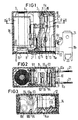
- the relay shown in FIGS. 1 to 3 has a base body 1 with a base part 2 and an essentially vertical partition 3, with which a magnet system space 4 is separated from a contact space 5.
- the magnet system has a coil 6, a yoke 7 and an armature 8, the switching movement of which is transmitted to a contact spring 10 via a slide 9, which will be described later.
- the contact spring 10 in turn works together with a fixed counter-contact element 11.
- An NC contact is shown in the example.
- a different arrangement of the counter-contact element can of course also provide a make contact or a changeover contact.
- a spring support 12 for the contact spring 10 is inserted from one outside into a receiving slot 13 of the base body, fixed with a tab 14 and additionally anchored by interlocking a fastening pin 14a.
- the mating contact element 11 is inserted into a corresponding receiving slot 15 of the base body and additionally anchored by means of a tab 16.
- the contact spring 10 and the mating contact element 11 are thus essentially perpendicular to the base of the base body and run approximately parallel to one another, with their contacting areas overlapping. As far as the respective mutual Distance to their connecting parts allows, the contact spring 10 and the mating contact element 11 extend over a large part of the width of the relay. They therefore have a large cross section for carrying high currents.
- connection rail 12a or 11a in the region of the base of the base body 1, both of which extend along the outer wall of the base body in the direction of the front side 17 of the relay. They thus run between the base body 1 and the side walls of a cap 18, which together with the base body forms the housing.
- an additional cover plate 19 is provided on the underside for sealing. Outside the housing, solder pins 20 and upward tabs 21 are then formed on the connecting rails 11a and 12a, respectively.
- This slide consists of a card and has an essentially U-shaped plan with which it encompasses the partition 3. It is coupled to the armature by a first arm 91, while the second arm 92 is in engagement with the contact spring 10.
- This second arm 92 itself is provided with an approximately U-shaped profile, a first outer leg 93 and a second outer leg 94 engaging in guide cutouts 10a and 10b of the contact spring 10 (see FIG. 3).
- the middle part of the actuating arm 92 forms a short actuating edge 95 which adjoins the outer leg 93 and which bears on the contact spring 10, while the edge 96 slants backwards laterally in order to enable free torsion of the contact spring 10.
- the contact piece 10c of the contact spring like the corresponding contact piece 11c of the counter-contact element 11, is arranged offset from the central axis of the contact spring opposite to the actuating edge 95. As a result, the effect of spring torsion comes into its own particularly well.
Landscapes
- Physics & Mathematics (AREA)
- Electromagnetism (AREA)
- Electromagnets (AREA)
- Relay Circuits (AREA)
- Breakers (AREA)
- Reciprocating, Oscillating Or Vibrating Motors (AREA)
- Video Image Reproduction Devices For Color Tv Systems (AREA)
- Motor Or Generator Current Collectors (AREA)
Claims (3)
- Relais électromagnétique de puissance ayant un jeu de contacts, qui comporte au moins un élément de contact antagoniste fixe (11) et un élément de contact mobile sous la forme d'un ressort à lame (10) encastré d'un côté, et un système magnétique, dont l'armature (8) agit sur ce ressort par l'intermédiaire d'un poussoir (9) pouvant être déplacé approximativement perpendiculairement à la direction longitudinale d'extension du ressort à lame (10), pour le déplacer d'une position de repos à une position de travail, le poussoir (9) attaquant d'une manière excentrée, exclusivement une zone marginale (95), sur le petit côté du ressort à lame (10), caractérisé en ce que le poussoir (9) a la forme d'une carte dont l'extrémité (92) tournée vers le ressort à lame (10), est réalisée approximativement avec une forme en U, les deux branches extérieures (93, 94) du profil en U s'engageant dans des découpes de guidage (10a, 10b) ménagées dans les deux zones marginales du ressort à lame (10), tandis que la partie médiane du profilé en U attaque exclusivement d'un côté (95) le ressort à lame (10).
- Relais suivant la revendication 1, caractérisé en ce que la pièce de contact (10c) du ressort à lame est décalée par rapport à l'axe médian du ressort de contact, à l'opposé du point d'actionnement (95).
- Relais suivant la revendication 1 ou 3, caractérisé en ce que la partie médiane du profilé en U a, à la suite d'une branche extérieure (93) un court élément d'actionnement (95), qui est parallèle à la surface du ressort à lame et auquel succède un élément de bord (96) formé par découpage à partir du ressort à lame (10).
Applications Claiming Priority (2)
| Application Number | Priority Date | Filing Date | Title |
|---|---|---|---|
| DE9013221U DE9013221U1 (de) | 1990-09-18 | 1990-09-18 | Elektromagnetisches Leistungsrelais mit Betätigungsschieber |
| DE9013221U | 1990-09-18 |
Publications (4)
| Publication Number | Publication Date |
|---|---|
| EP0476182A2 EP0476182A2 (fr) | 1992-03-25 |
| EP0476182A3 EP0476182A3 (en) | 1992-09-02 |
| EP0476182B1 EP0476182B1 (fr) | 1994-09-28 |
| EP0476182B2 true EP0476182B2 (fr) | 1997-04-16 |
Family
ID=6857615
Family Applications (1)
| Application Number | Title | Priority Date | Filing Date |
|---|---|---|---|
| EP90124826A Expired - Lifetime EP0476182B2 (fr) | 1990-09-18 | 1990-12-19 | Contacteur électromagnétique avec un coulisseau de commande |
Country Status (7)
| Country | Link |
|---|---|
| US (1) | US5144270A (fr) |
| EP (1) | EP0476182B2 (fr) |
| JP (1) | JPH04245126A (fr) |
| AT (1) | ATE112414T1 (fr) |
| CA (1) | CA2051478A1 (fr) |
| DE (2) | DE9013221U1 (fr) |
| PT (1) | PT98988B (fr) |
Families Citing this family (10)
| Publication number | Priority date | Publication date | Assignee | Title |
|---|---|---|---|---|
| DE4115092C3 (de) * | 1991-05-08 | 1999-06-24 | Eberle Controls Gmbh | Elektromagnetisches Schaltrelais für Leiterplattenmontage |
| AT410856B (de) * | 1994-07-08 | 2003-08-25 | Tyco Electronics Austria Gmbh | Relais |
| JP4677916B2 (ja) * | 2006-02-08 | 2011-04-27 | オムロン株式会社 | 電磁継電器 |
| US7477119B2 (en) * | 2007-03-02 | 2009-01-13 | Good Sky Electric Co., Ltd. | Electromagnetic relay |
| JP5720840B2 (ja) * | 2013-09-27 | 2015-05-20 | オムロン株式会社 | 接点機構部およびこれを備えた電磁継電器 |
| US9536691B1 (en) | 2014-07-10 | 2017-01-03 | Google Inc. | Axial relay |
| FR3082353B1 (fr) | 2018-06-08 | 2022-11-04 | Langlade & Picard | Dispositif mobile de basculement (f) pour relais electromagnetique monostable basse-tension (entre 110v et 400v) |
| JP7183014B2 (ja) * | 2018-11-30 | 2022-12-05 | 富士通コンポーネント株式会社 | 電磁継電器、及び電磁継電器の製造方法 |
| US11501938B2 (en) * | 2019-07-09 | 2022-11-15 | Xiamen Hongfa Electroacoustic Co., Ltd. | Magnetic latching relay |
| JP7555026B2 (ja) * | 2021-01-06 | 2024-09-24 | パナソニックIpマネジメント株式会社 | 電磁継電器 |
Family Cites Families (7)
| Publication number | Priority date | Publication date | Assignee | Title |
|---|---|---|---|---|
| DE2732723C2 (de) * | 1977-07-20 | 1984-07-26 | Diehl GmbH & Co, 8500 Nürnberg | Elektrische Schaltvorrichtung |
| DE2912800C2 (de) * | 1979-03-30 | 1985-04-25 | Siemens AG, 1000 Berlin und 8000 München | Elektromagnetisches Relais für hohe Schaltleistungen |
| DE3002079A1 (de) * | 1980-01-21 | 1981-07-23 | Siemens AG, 1000 Berlin und 8000 München | Relais |
| DE3347602A1 (de) * | 1983-12-30 | 1985-07-11 | Siemens AG, 1000 Berlin und 8000 München | Polarisiertes elektromagnetisches relais |
| US4937544A (en) * | 1988-01-29 | 1990-06-26 | Siemens Aktiengesellschaft | "Contact arrangement for a relay" |
| DE3835118A1 (de) * | 1988-10-14 | 1990-04-19 | Siemens Ag | Elektromagnetisches relais |
| JPH0346728A (ja) * | 1989-07-13 | 1991-02-28 | Omron Corp | 電磁継電器 |
-
1990
- 1990-09-18 DE DE9013221U patent/DE9013221U1/de not_active Expired - Lifetime
- 1990-12-19 EP EP90124826A patent/EP0476182B2/fr not_active Expired - Lifetime
- 1990-12-19 DE DE59007351T patent/DE59007351D1/de not_active Expired - Fee Related
- 1990-12-19 AT AT90124826T patent/ATE112414T1/de not_active IP Right Cessation
-
1991
- 1991-07-03 US US07/725,642 patent/US5144270A/en not_active Expired - Lifetime
- 1991-09-12 JP JP3232761A patent/JPH04245126A/ja active Pending
- 1991-09-16 CA CA002051478A patent/CA2051478A1/fr not_active Abandoned
- 1991-09-17 PT PT98988A patent/PT98988B/pt not_active IP Right Cessation
Also Published As
| Publication number | Publication date |
|---|---|
| EP0476182A3 (en) | 1992-09-02 |
| EP0476182A2 (fr) | 1992-03-25 |
| DE9013221U1 (de) | 1992-01-23 |
| EP0476182B1 (fr) | 1994-09-28 |
| ATE112414T1 (de) | 1994-10-15 |
| US5144270A (en) | 1992-09-01 |
| CA2051478A1 (fr) | 1992-03-19 |
| PT98988B (pt) | 1999-01-29 |
| DE59007351D1 (de) | 1994-11-03 |
| JPH04245126A (ja) | 1992-09-01 |
| PT98988A (pt) | 1993-10-29 |
Similar Documents
| Publication | Publication Date | Title |
|---|---|---|
| DE19727991C1 (de) | Elektromagnetisches Relais | |
| DE2939178C2 (fr) | ||
| DE2912800C2 (de) | Elektromagnetisches Relais für hohe Schaltleistungen | |
| DE2803249A1 (de) | Loeschglied fuer lichtbogen | |
| EP0281950B1 (fr) | Relais électromagnétique | |
| EP0476182B2 (fr) | Contacteur électromagnétique avec un coulisseau de commande | |
| DE9001448U1 (de) | Schaltvorrichtung mit geschützten Unterbrechern | |
| EP0203515B1 (fr) | Relais électromagnétique | |
| DE3431703C2 (de) | Tastschalter | |
| DE102007019684A1 (de) | Magnetsystem für eine elektrische Schaltvorrichtung | |
| DE3224468A1 (de) | Relais mit brueckenkontaktfeder | |
| EP3516676A1 (fr) | Relais electromagnetique | |
| DE2928214A1 (de) | Schnappschalter | |
| EP0081164A1 (fr) | Relais électromagnétique | |
| EP0013991B2 (fr) | Dispositif à ressorts de contact pour relais électromagnétiques polarisés | |
| EP0170172A1 (fr) | Relais piézoélectrique | |
| DE3118292C2 (de) | Elektromagnetisches Relais | |
| EP0763247B1 (fr) | Interrupteur a action brusque, a deplacement rectiligne du contact et systeme d'interrupteur associe | |
| EP0634767B1 (fr) | Relais | |
| EP0494278B1 (fr) | Commutateur electrique | |
| EP0068483A1 (fr) | Commutateur électromécanique pour appareils téléphoniques | |
| DE3545356C2 (de) | Sicherheits-Schaltrelais | |
| DE3940285C2 (fr) | ||
| EP1473752A1 (fr) | Déclencheur électromagnétique | |
| DE68927238T2 (de) | Elektromagnetisches Relais |
Legal Events
| Date | Code | Title | Description |
|---|---|---|---|
| PUAI | Public reference made under article 153(3) epc to a published international application that has entered the european phase |
Free format text: ORIGINAL CODE: 0009012 |
|
| 17P | Request for examination filed |
Effective date: 19901219 |
|
| AK | Designated contracting states |
Kind code of ref document: A2 Designated state(s): AT CH DE ES FR GB IT LI |
|
| PUAL | Search report despatched |
Free format text: ORIGINAL CODE: 0009013 |
|
| AK | Designated contracting states |
Kind code of ref document: A3 Designated state(s): AT CH DE ES FR GB IT LI |
|
| 17Q | First examination report despatched |
Effective date: 19940304 |
|
| GRAA | (expected) grant |
Free format text: ORIGINAL CODE: 0009210 |
|
| AK | Designated contracting states |
Kind code of ref document: B1 Designated state(s): AT CH DE ES FR GB IT LI |
|
| PG25 | Lapsed in a contracting state [announced via postgrant information from national office to epo] |
Ref country code: ES Free format text: THE PATENT HAS BEEN ANNULLED BY A DECISION OF A NATIONAL AUTHORITY Effective date: 19940928 |
|
| REF | Corresponds to: |
Ref document number: 112414 Country of ref document: AT Date of ref document: 19941015 Kind code of ref document: T |
|
| REF | Corresponds to: |
Ref document number: 59007351 Country of ref document: DE Date of ref document: 19941103 |
|
| ET | Fr: translation filed | ||
| ITF | It: translation for a ep patent filed | ||
| GBT | Gb: translation of ep patent filed (gb section 77(6)(a)/1977) |
Effective date: 19941205 |
|
| PLBI | Opposition filed |
Free format text: ORIGINAL CODE: 0009260 |
|
| 26 | Opposition filed |
Opponent name: EH - SCHRACK COMPONENTS-AKTIENGESELLSCHAFT Effective date: 19950627 |
|
| PGFP | Annual fee paid to national office [announced via postgrant information from national office to epo] |
Ref country code: CH Payment date: 19960320 Year of fee payment: 6 |
|
| PLAW | Interlocutory decision in opposition |
Free format text: ORIGINAL CODE: EPIDOS IDOP |
|
| PLAW | Interlocutory decision in opposition |
Free format text: ORIGINAL CODE: EPIDOS IDOP |
|
| PGFP | Annual fee paid to national office [announced via postgrant information from national office to epo] |
Ref country code: AT Payment date: 19961127 Year of fee payment: 7 |
|
| PG25 | Lapsed in a contracting state [announced via postgrant information from national office to epo] |
Ref country code: LI Effective date: 19961231 Ref country code: CH Effective date: 19961231 |
|
| PUAH | Patent maintained in amended form |
Free format text: ORIGINAL CODE: 0009272 |
|
| STAA | Information on the status of an ep patent application or granted ep patent |
Free format text: STATUS: PATENT MAINTAINED AS AMENDED |
|
| 27A | Patent maintained in amended form |
Effective date: 19970416 |
|
| AK | Designated contracting states |
Kind code of ref document: B2 Designated state(s): AT CH DE ES FR GB IT LI |
|
| REG | Reference to a national code |
Ref country code: CH Ref legal event code: AEN Free format text: AUFRECHTERHALTUNG DES PATENTES IN GEAENDERTER FORM |
|
| ET3 | Fr: translation filed ** decision concerning opposition | ||
| GBTA | Gb: translation of amended ep patent filed (gb section 77(6)(b)/1977) | ||
| REG | Reference to a national code |
Ref country code: CH Ref legal event code: PL |
|
| PG25 | Lapsed in a contracting state [announced via postgrant information from national office to epo] |
Ref country code: AT Free format text: LAPSE BECAUSE OF NON-PAYMENT OF DUE FEES Effective date: 19971219 |
|
| PGFP | Annual fee paid to national office [announced via postgrant information from national office to epo] |
Ref country code: GB Payment date: 19981210 Year of fee payment: 9 |
|
| PGFP | Annual fee paid to national office [announced via postgrant information from national office to epo] |
Ref country code: FR Payment date: 19981218 Year of fee payment: 9 |
|
| PG25 | Lapsed in a contracting state [announced via postgrant information from national office to epo] |
Ref country code: GB Free format text: LAPSE BECAUSE OF NON-PAYMENT OF DUE FEES Effective date: 19991219 |
|
| GBPC | Gb: european patent ceased through non-payment of renewal fee |
Effective date: 19991219 |
|
| PG25 | Lapsed in a contracting state [announced via postgrant information from national office to epo] |
Ref country code: FR Free format text: LAPSE BECAUSE OF NON-PAYMENT OF DUE FEES Effective date: 20000831 |
|
| REG | Reference to a national code |
Ref country code: FR Ref legal event code: ST |
|
| PGFP | Annual fee paid to national office [announced via postgrant information from national office to epo] |
Ref country code: DE Payment date: 20080131 Year of fee payment: 18 Ref country code: IT Payment date: 20071229 Year of fee payment: 18 |
|
| PG25 | Lapsed in a contracting state [announced via postgrant information from national office to epo] |
Ref country code: DE Free format text: LAPSE BECAUSE OF NON-PAYMENT OF DUE FEES Effective date: 20090701 |
|
| PG25 | Lapsed in a contracting state [announced via postgrant information from national office to epo] |
Ref country code: IT Free format text: LAPSE BECAUSE OF NON-PAYMENT OF DUE FEES Effective date: 20081219 |