EP0476392A1 - Dispositif de coupe et de formage pour un appareil de production de petits pains - Google Patents
Dispositif de coupe et de formage pour un appareil de production de petits pains Download PDFInfo
- Publication number
- EP0476392A1 EP0476392A1 EP91114593A EP91114593A EP0476392A1 EP 0476392 A1 EP0476392 A1 EP 0476392A1 EP 91114593 A EP91114593 A EP 91114593A EP 91114593 A EP91114593 A EP 91114593A EP 0476392 A1 EP0476392 A1 EP 0476392A1
- Authority
- EP
- European Patent Office
- Prior art keywords
- cutting
- die
- annular disc
- die pieces
- disc
- Prior art date
- Legal status (The legal status is an assumption and is not a legal conclusion. Google has not performed a legal analysis and makes no representation as to the accuracy of the status listed.)
- Granted
Links
- 238000007599 discharging Methods 0.000 claims 1
- 230000000284 resting effect Effects 0.000 claims 1
- 238000004519 manufacturing process Methods 0.000 description 1
- 235000013372 meat Nutrition 0.000 description 1
- 238000000034 method Methods 0.000 description 1
- 230000002093 peripheral effect Effects 0.000 description 1
Images


Classifications
-
- A—HUMAN NECESSITIES
- A21—BAKING; EDIBLE DOUGHS
- A21C—MACHINES OR EQUIPMENT FOR MAKING OR PROCESSING DOUGHS; HANDLING BAKED ARTICLES MADE FROM DOUGH
- A21C11/00—Other machines for forming the dough into its final shape before cooking or baking
-
- A—HUMAN NECESSITIES
- A21—BAKING; EDIBLE DOUGHS
- A21C—MACHINES OR EQUIPMENT FOR MAKING OR PROCESSING DOUGHS; HANDLING BAKED ARTICLES MADE FROM DOUGH
- A21C11/00—Other machines for forming the dough into its final shape before cooking or baking
- A21C11/10—Other machines for forming the dough into its final shape before cooking or baking combined with cutting apparatus
- A21C11/103—Other machines for forming the dough into its final shape before cooking or baking combined with cutting apparatus having multiple cutting elements slidably or rotably mounted in a diaphragm-like arrangement
Definitions
- the apparatus for making buns described in U.S. Letter Pat. No. 4,636,158 comprises a meat feeding unit, a dough feeding unit and a bun forming unit, wherein a dough is continuously processed to become a bun.
- the dough may lose its viscosity because of the heat produced and thus finished buns may lose their delicious taste.
- the circular plate and the die pieces may have problems in their interrelation as to make the die pieces close together, such as the correctness of the angle of each die piece, the exactness of the distance from the pointed tip of the die piece to the fixing post.
- Each die piece has to have a recess opening at its bottom side to receive a bearing and a spring to urge the bearing and the front edge of the recess opening. But if the elasticity of the spring is not proper, all the ide pieces can not be pushed ot close together for cutting the dough. So the structure of the die piece and related components are rather complicated, and inconvenient to manufacture.
- An object of the present invention is to provide a cutting and forming device with simple structure for an apparatus for making buns.
- the cutting and forming device for an apparatus for making buns in the present invention comprises a number of die pieces, a base plate, a rotary annular disc and an operating mechanism.
- Each die piece has an outer portion and an inner portion combined together.
- the outer portion has a square section and a tubular section of smaller size than the square section and extending inward lengthwise from the square section.
- the square section has at the inner end a screw hole for a screw to pass through for fixing it on the base plate and a protruding upright post at the outer end to fit movably in an elongate hole in the rotary annular disc.
- the tubular section fits in a lengthwise hole in the inner portion and contains a coiled spring having one end urging the end face of the square section and the other end urging a bottom face of the lengthwise hole in the inner portion.
- the base plate is provided with a central opening for dough to pass through and a number of screw holes arranged concentrically around the central opening for screwing all the die pieces radially on its lateral surface. All die pieces can move rotatingly with the screws as the pivots.
- the rotary annular disc is provided with a number of elongate holes equally spaced apart radially a little far from and around the central opening and having the same distance to the center of the rotary annular disc.
- the rotary annular disc is to be placed laterally on all of the die pieces screwed on the base plate, with its elongate holes being fitted in by the protruding posts of the die pieces, and so the die pieces are sandwiched between the base plate and the rotary annular disc if viewed cross- sectionally.
- the operating mechanism comprises a fly wheel eccentrically combined with a connecting rod and then with a push rod, which is connected at both ends with two push arms having their one end connected with the rotary annular disc.
- the fly wheel When the fly wheel is continually rotated, the rotary annular disc can be rotated reciprocatingly in a limited angle clockwise or counterclockwise and all of the die pieces can be moved radially from a released position to a cutting and forming position or vice versa continually by the movement of the rotary annular disc. Therefore, dough coming down through the central opening of the base plate can be continually cut and formed into buns by the movement of the die pieces.
- the cutting and forming device of the present invention comprises a number of die pieces 1, base plate 2, a rotary annular disc 38 and an operating mechanism 3.
- a die piece 1 provided in the cutting device for an apparatus for making buns has an outer portion 11 and and inner portion 12.
- the outer portion 11 has a square section and a tubular section 113 of smaller size than the square section and extending inward lengthwise from the inner end of the square section.
- the square section has a screw hole 112 at the inner end for a screw 112 to pass through to fix the die piece 1 on the base plate 2 and the die piece 1 can move pivot on the screw 112.
- the tubular section 113 fits in a lengthwise hole 121 in the inner portion 12.
- a coiled spring 13 is contained in the inner cavity of the tubular section 113, having one of its ends urging the bottom face of the hole 121 in the inner portion 12 and the other end urging the end face of the square section such that the inner portion 12 can be extended forward or retracted backward relative to the outer portion 11.
- the outer portion 11 has a protruding post 114 upright at the outer end on the same surface as the screw hole 11.
- the protruding post 114 fits movably in an elongate hole 381 in a rotary annular disc 38.
- the inner portion 12 of the die piece 1 is used for cutting dough and forming it into a bun and is urged forward by the elasticity of the coiled spring 13 contained in the tubular section 113.
- the inner portion 12 has a pointed cutting tip 122 at its front end, and the cutting tip 122 of each die piece 1 has such a contained angle that the cutting tips 122 of all the die pieces 1 included in this cutting device can constitute 360 0, no matter how many die pieces 1 are used.
- At the upside and the downside of the cutting tip 122 are provided curved faces 123 and 124, and the curved face 124 can form a dough cut into a bun. Just controlling the time for forming a dough into a bun can change the volume of a dough coming down to be cut, and thus to get different sized products. Besides, the bottom of a dough cut can also be formed to close up at the same time.
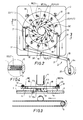
- FIGS. 2 and 3 show a base plate 2, which has a central opening 21 for a tubular dough coming down from a supplying tube 4 to pass through, and a number of screw holes 22 set concentrically with the opening 21 in the same distance between one another for screws 112 to screw therein for fixing the outer portion 11 of each die piece 1 on the lateral surface of the base plate 2. All die pieces can pivot on the screws 112. The cutting tip 122 of the die piece 1 rests against an adjacent die piece 1 such that all of die pieces 1 may form almost a circle with their inner end backs when they are in a released position as shown in FIG. 2. The number of the die pieces is preferably even.
- the protruding post 114 fits in an elongate hole 381 in the rotary annular disc 38 and the distance between the two ends of the elongate hole 381 and the center of the rotary disc 38 are different such that the protruding post 114 can be moved along the hole 381 when the rotary disc 38 is rotated, usually staying at the spot therein nearest to the center of the rotary annular disc 38 and making all of the cutting tips 122 form almost a circle as shown in FIG. 2.
- An operating mechanism 3 includes a fly wheel 33, a connecting rod 34 eccentrically connected with the fly wheel 33 at one end and connected at the other end with a push rod 35, which has a central fulcrum 36 just at the middle and two ac- tional fulcrums 37 at both sides of the fulcrum 36, and one end of two push arms 31, which have their other ends connected with the rotary annular disc 38 by means of pins 32.
- the push arms 31 move up and down reciprocatingly, rotating the rotary annular disc 38 in a limited angle clockwise and counterclockwise, and moreover, a plurality of position bearings 39 are provided on the base plate 2 around the peripheral edge of the rotary annular disc 38 to urge it to make a stable reciprocating rotation in a limited angle.
- the disc rotation causes die pieces 1 to move reciprocatingly in a limited angle with the screws 112 as pivots and iwth the protruding posts 114 fitting in and being moved by the elongate holes 381 in the rotary disc 38. Accordingly, the inner portions 12 of the die pieces 1 smoothly and evenly retract and extend.
- the right push arm 31 is pulled downward as shown in FIGS.
- the left push arm 31 is pushed upward and the protruding posts 114 stay almost at the middle of the elongate holes 38 forcing all of the cutting tips 122 of the die pieces 1 to extend to form a circle large enough for the tubular dough to pass through downward.
- the protruding posts 114 are moved to the farthest spot in the elongate holes 381 from the center of the rotary disc 38, and the cutting tips 122 of all the die pieces 1 are extended to gather at the center of the central opening 21 of the base plate 2 resiliently pushed by the coiled springs 13. Then the tubular dough coming down from the supplying tube 4, and passing through among the die pieces 1 is cut and the piece of the dough cut off by the die pieces is formed into a bun and the end of the dough on the die pieces 1 becomes the bottom of the next bun to be cut. The finished bun automatically drops on the conveying belt 5 when the die pieces 1 are opened.
Landscapes
- Life Sciences & Earth Sciences (AREA)
- Engineering & Computer Science (AREA)
- Food Science & Technology (AREA)
- Manufacturing And Processing Devices For Dough (AREA)
- Details Of Cutting Devices (AREA)
- Perforating, Stamping-Out Or Severing By Means Other Than Cutting (AREA)
- Bakery Products And Manufacturing Methods Therefor (AREA)
Applications Claiming Priority (2)
| Application Number | Priority Date | Filing Date | Title |
|---|---|---|---|
| US07/580,574 US5031520A (en) | 1990-09-11 | 1990-09-11 | Cutting and forming device for an apparatus for making buns |
| US580574 | 1990-09-11 |
Publications (2)
| Publication Number | Publication Date |
|---|---|
| EP0476392A1 true EP0476392A1 (fr) | 1992-03-25 |
| EP0476392B1 EP0476392B1 (fr) | 1994-10-26 |
Family
ID=24321651
Family Applications (1)
| Application Number | Title | Priority Date | Filing Date |
|---|---|---|---|
| EP91114593A Expired - Lifetime EP0476392B1 (fr) | 1990-09-11 | 1991-08-30 | Dispositif de coupe et de formage pour un appareil de production de petits pains |
Country Status (8)
| Country | Link |
|---|---|
| US (1) | US5031520A (fr) |
| EP (1) | EP0476392B1 (fr) |
| KR (1) | KR940006254Y1 (fr) |
| CN (1) | CN1027219C (fr) |
| AT (1) | ATE113169T1 (fr) |
| CA (1) | CA2050419C (fr) |
| DE (1) | DE69104804T2 (fr) |
| MY (1) | MY108077A (fr) |
Cited By (4)
| Publication number | Priority date | Publication date | Assignee | Title |
|---|---|---|---|---|
| FR2805126A1 (fr) * | 2000-02-18 | 2001-08-24 | Young Robert Ou | Procede de formage d'un corps spherique et dispositif a cette fin |
| GB2389067A (en) * | 2002-05-28 | 2003-12-03 | Robert Ou-Young | Moulding device and cutter for food products |
| US7802981B2 (en) * | 2006-10-12 | 2010-09-28 | Delta Electronics Components (Dongguan) Co., Ltd. | Device for extracting a mold core from a mold assembly, and mold assembly using the device |
| US7901198B2 (en) * | 2005-12-21 | 2011-03-08 | Rheon Automatic Machinery Co., Ltd. | Shape-forming shutter apparatus and shutter piece thereof |
Families Citing this family (17)
| Publication number | Priority date | Publication date | Assignee | Title |
|---|---|---|---|---|
| US5820890A (en) * | 1992-01-30 | 1998-10-13 | Kobird Co., Ltd. | Apparatus for cutting plastic bar-shaped food |
| GB2271707A (en) * | 1992-10-26 | 1994-04-27 | Tsay Shih Chu | Apparatus for making stuffed buns |
| JP2979131B2 (ja) * | 1995-07-31 | 1999-11-15 | レオン自動機株式会社 | 丸みを有する食品シート状生地の間欠吐出装置 |
| JP2860937B2 (ja) * | 1996-08-08 | 1999-02-24 | レオン自動機株式会社 | フチ付き製品の製造方法および装置 |
| JP3016246B2 (ja) * | 1996-09-25 | 2000-03-06 | レオン自動機株式会社 | 包被切断装置 |
| US6257863B1 (en) * | 1997-10-31 | 2001-07-10 | Industrial Thermo Polymers Limited | Extruder dies with shaping means |
| TW359079U (en) * | 1998-09-30 | 1999-05-21 | Yu Ouyang | Improvement of knife blade for the forming tool in food processor |
| JP3363843B2 (ja) * | 1999-07-26 | 2003-01-08 | レオン自動機株式会社 | 包被切断機 |
| US6892630B1 (en) * | 2004-01-22 | 2005-05-17 | Lien-Fu Huang | Device for molding spheroidal food products |
| US7883735B2 (en) * | 2006-08-07 | 2011-02-08 | Kellogg Company | Apparatus and method for curled extrudate |
| JP5984892B2 (ja) * | 2014-01-29 | 2016-09-06 | レオン自動機株式会社 | シャッタ片及び食品成形装置 |
| CN103976460B (zh) * | 2014-05-12 | 2016-01-20 | 厦门理工学院 | 一种包心丸子加工机 |
| CN108943063A (zh) * | 2018-06-25 | 2018-12-07 | 界首市华盛塑料机械有限公司 | 一种功能性食品加工用切片装置 |
| CN109511701A (zh) * | 2018-09-25 | 2019-03-26 | 王晓杰 | 一种食品切断加工机和包子机 |
| IT201900020823A1 (it) * | 2019-11-11 | 2021-05-11 | Marotta Evolution S R L | Apparecchiatura per la produzione di formaggi ripieni, particolarmente burrate |
| CN111887270B (zh) * | 2020-07-31 | 2021-12-21 | 李伟杰 | 一种包子自动生产设备 |
| CN114931120A (zh) * | 2022-07-04 | 2022-08-23 | 南方海洋科学与工程广东省实验室(湛江) | 一种柔性连接的投饵分配器及养殖投饵系统 |
Citations (7)
| Publication number | Priority date | Publication date | Assignee | Title |
|---|---|---|---|---|
| DE272176C (fr) * | ||||
| GB1109137A (en) * | 1964-08-01 | 1968-04-10 | Basf Ag | Production of hollow articles from thermoplastics by blow moulding |
| GB1148575A (en) * | 1965-04-13 | 1969-04-16 | Elastomer Ag | A machine for the manufacture of rings or disks |
| GB1418699A (en) * | 1973-12-13 | 1975-12-24 | Campbell Soup Co | Apparatus for extruding spherically-shaped food products |
| US3954033A (en) * | 1974-06-27 | 1976-05-04 | The United States Of America As Represented By The Secretary Of The Department Of Health, Education And Welfare | Method and apparatus for cutting cylinders of gelatinous materials into discs of precise thickness |
| US4636158A (en) * | 1985-11-14 | 1987-01-13 | Huang Der S | Apparatus for making bun |
| GB2195935A (en) * | 1986-09-25 | 1988-04-20 | Metal Box Plc | Rotary cutting apparatus for tubes |
Family Cites Families (9)
| Publication number | Priority date | Publication date | Assignee | Title |
|---|---|---|---|---|
| US3190330A (en) * | 1963-05-20 | 1965-06-22 | Michael L Antos | Garnish cutter for fruit and vegetables |
| US3430290A (en) * | 1966-08-01 | 1969-03-04 | Phillips Petroleum Co | Apparatus for sealing and severing parisons |
| US3520010A (en) * | 1967-02-20 | 1970-07-14 | Phillips Petroleum Co | Parison severing means having blade with sharp edge and offset top surface |
| US3572259A (en) * | 1969-07-08 | 1971-03-23 | Torahiko Hayashi | Apparatus for molding elastic dough materials from bar shapes into spherical shapes |
| JPS5831180B2 (ja) * | 1980-01-16 | 1983-07-04 | 株式会社 ハイト | 包あん方法及び包あん機 |
| US4336010A (en) * | 1980-09-02 | 1982-06-22 | Thompson Daniel T | Dough forming, dividing and cutting apparatus |
| GB2101924B (en) * | 1981-05-13 | 1985-06-05 | Masao Kobayashi | Apparatus for forming soft food material into globular shape |
| JPS60160179U (ja) * | 1984-04-04 | 1985-10-24 | 鈴木 喜作 | 食品成形機における材料供給機構 |
| US4936203A (en) * | 1988-09-03 | 1990-06-26 | Rheon Automatic Machinery Co., Ltd. | Apparatus for shaping and arraying spheroidal bodies of food materials |
-
1990
- 1990-09-11 US US07/580,574 patent/US5031520A/en not_active Expired - Fee Related
-
1991
- 1991-04-02 CN CN91102208A patent/CN1027219C/zh not_active Expired - Fee Related
- 1991-08-30 AT AT91114593T patent/ATE113169T1/de not_active IP Right Cessation
- 1991-08-30 EP EP91114593A patent/EP0476392B1/fr not_active Expired - Lifetime
- 1991-08-30 CA CA002050419A patent/CA2050419C/fr not_active Expired - Fee Related
- 1991-08-30 DE DE69104804T patent/DE69104804T2/de not_active Expired - Fee Related
- 1991-09-05 KR KR2019910014425U patent/KR940006254Y1/ko not_active Expired - Fee Related
- 1991-10-20 MY MYPI91001517A patent/MY108077A/en unknown
Patent Citations (7)
| Publication number | Priority date | Publication date | Assignee | Title |
|---|---|---|---|---|
| DE272176C (fr) * | ||||
| GB1109137A (en) * | 1964-08-01 | 1968-04-10 | Basf Ag | Production of hollow articles from thermoplastics by blow moulding |
| GB1148575A (en) * | 1965-04-13 | 1969-04-16 | Elastomer Ag | A machine for the manufacture of rings or disks |
| GB1418699A (en) * | 1973-12-13 | 1975-12-24 | Campbell Soup Co | Apparatus for extruding spherically-shaped food products |
| US3954033A (en) * | 1974-06-27 | 1976-05-04 | The United States Of America As Represented By The Secretary Of The Department Of Health, Education And Welfare | Method and apparatus for cutting cylinders of gelatinous materials into discs of precise thickness |
| US4636158A (en) * | 1985-11-14 | 1987-01-13 | Huang Der S | Apparatus for making bun |
| GB2195935A (en) * | 1986-09-25 | 1988-04-20 | Metal Box Plc | Rotary cutting apparatus for tubes |
Cited By (6)
| Publication number | Priority date | Publication date | Assignee | Title |
|---|---|---|---|---|
| FR2805126A1 (fr) * | 2000-02-18 | 2001-08-24 | Young Robert Ou | Procede de formage d'un corps spherique et dispositif a cette fin |
| NL1017025C2 (nl) * | 2000-02-18 | 2002-07-17 | Robert Ou-Yonug | Werkwijze en inrichting voor het vormen van een sferisch lichaam. |
| GB2389067A (en) * | 2002-05-28 | 2003-12-03 | Robert Ou-Young | Moulding device and cutter for food products |
| FR2840157A1 (fr) * | 2002-05-28 | 2003-12-05 | Young Robert Ou | Dispositif de moulage pour des produits a base de pate |
| US7901198B2 (en) * | 2005-12-21 | 2011-03-08 | Rheon Automatic Machinery Co., Ltd. | Shape-forming shutter apparatus and shutter piece thereof |
| US7802981B2 (en) * | 2006-10-12 | 2010-09-28 | Delta Electronics Components (Dongguan) Co., Ltd. | Device for extracting a mold core from a mold assembly, and mold assembly using the device |
Also Published As
| Publication number | Publication date |
|---|---|
| DE69104804D1 (de) | 1994-12-01 |
| DE69104804T2 (de) | 1995-03-02 |
| CA2050419C (fr) | 1995-02-21 |
| ATE113169T1 (de) | 1994-11-15 |
| KR920005728U (ko) | 1992-04-21 |
| EP0476392B1 (fr) | 1994-10-26 |
| US5031520A (en) | 1991-07-16 |
| KR940006254Y1 (ko) | 1994-09-16 |
| CA2050419A1 (fr) | 1992-03-12 |
| MY108077A (en) | 1996-08-15 |
| CN1027219C (zh) | 1995-01-04 |
| CN1059639A (zh) | 1992-03-25 |
Similar Documents
| Publication | Publication Date | Title |
|---|---|---|
| US5031520A (en) | Cutting and forming device for an apparatus for making buns | |
| US5873294A (en) | Semi-automatic tool for cutting pizzas into pieces of the same size | |
| AU2011284029B2 (en) | Tablet splitting apparatus | |
| US4912885A (en) | Knife sharpener | |
| US2247650A (en) | Lemon slicer | |
| CN115179335A (zh) | 一种中药饮片自动化切片设备 | |
| US2291449A (en) | Slicing machine | |
| US2977901A (en) | Hard roll scorer and former | |
| US5329843A (en) | Cherry pitter | |
| US1939279A (en) | Bun cutting machine | |
| CN111557854A (zh) | 一种方便于连续分割的圆药片分药器 | |
| CN205704322U (zh) | 一种多功能料理机 | |
| US2811188A (en) | Egg opener | |
| US2035339A (en) | Slicing machine | |
| US2553377A (en) | Collapsible container and stand therefor | |
| US5974934A (en) | Apparatus for making a bowl from a loaf of bread | |
| US2174329A (en) | Insulin bottle and syringe holder | |
| KR200315712Y1 (ko) | 무 써는 기구 | |
| CN221475346U (zh) | 一种新型分药器 | |
| US4099806A (en) | Combined opthalmic lens pattern rack and dispenser | |
| US2702572A (en) | Cake slicing machine | |
| CN215094036U (zh) | 一种中药加工用可调节切片方向的切制装置 | |
| SU959982A1 (ru) | Автомат дл подачи и сборки деталей | |
| US1095620A (en) | Potato-cutting machine. | |
| JP2989032B2 (ja) | らっきょう等裁断時の姿勢制御方法および裁断装置 |
Legal Events
| Date | Code | Title | Description |
|---|---|---|---|
| PUAI | Public reference made under article 153(3) epc to a published international application that has entered the european phase |
Free format text: ORIGINAL CODE: 0009012 |
|
| AK | Designated contracting states |
Kind code of ref document: A1 Designated state(s): AT BE CH DE DK ES FR GB GR IT LI LU NL SE |
|
| 17P | Request for examination filed |
Effective date: 19920512 |
|
| 17Q | First examination report despatched |
Effective date: 19930504 |
|
| GRAA | (expected) grant |
Free format text: ORIGINAL CODE: 0009210 |
|
| AK | Designated contracting states |
Kind code of ref document: B1 Designated state(s): AT BE CH DE DK ES FR GB GR IT LI LU NL SE |
|
| PG25 | Lapsed in a contracting state [announced via postgrant information from national office to epo] |
Ref country code: NL Effective date: 19941026 Ref country code: GR Free format text: LAPSE BECAUSE OF FAILURE TO SUBMIT A TRANSLATION OF THE DESCRIPTION OR TO PAY THE FEE WITHIN THE PRESCRIBED TIME-LIMIT Effective date: 19941026 Ref country code: ES Free format text: THE PATENT HAS BEEN ANNULLED BY A DECISION OF A NATIONAL AUTHORITY Effective date: 19941026 Ref country code: DK Effective date: 19941026 Ref country code: BE Effective date: 19941026 Ref country code: AT Effective date: 19941026 |
|
| REF | Corresponds to: |
Ref document number: 113169 Country of ref document: AT Date of ref document: 19941115 Kind code of ref document: T |
|
| REF | Corresponds to: |
Ref document number: 69104804 Country of ref document: DE Date of ref document: 19941201 |
|
| ET | Fr: translation filed | ||
| ITF | It: translation for a ep patent filed | ||
| EAL | Se: european patent in force in sweden |
Ref document number: 91114593.6 |
|
| NLV1 | Nl: lapsed or annulled due to failure to fulfill the requirements of art. 29p and 29m of the patents act | ||
| PLBE | No opposition filed within time limit |
Free format text: ORIGINAL CODE: 0009261 |
|
| STAA | Information on the status of an ep patent application or granted ep patent |
Free format text: STATUS: NO OPPOSITION FILED WITHIN TIME LIMIT |
|
| PG25 | Lapsed in a contracting state [announced via postgrant information from national office to epo] |
Ref country code: GB Effective date: 19950830 |
|
| PG25 | Lapsed in a contracting state [announced via postgrant information from national office to epo] |
Ref country code: SE Effective date: 19950831 Ref country code: LU Free format text: LAPSE BECAUSE OF NON-PAYMENT OF DUE FEES Effective date: 19950831 Ref country code: LI Effective date: 19950831 Ref country code: CH Effective date: 19950831 |
|
| 26N | No opposition filed | ||
| REG | Reference to a national code |
Ref country code: CH Ref legal event code: PL |
|
| PG25 | Lapsed in a contracting state [announced via postgrant information from national office to epo] |
Ref country code: FR Effective date: 19960430 |
|
| GBPC | Gb: european patent ceased through non-payment of renewal fee |
Effective date: 19950830 |
|
| PG25 | Lapsed in a contracting state [announced via postgrant information from national office to epo] |
Ref country code: DE Effective date: 19960501 |
|
| EUG | Se: european patent has lapsed |
Ref document number: 91114593.6 |
|
| REG | Reference to a national code |
Ref country code: FR Ref legal event code: ST |
|
| PG25 | Lapsed in a contracting state [announced via postgrant information from national office to epo] |
Ref country code: IT Free format text: LAPSE BECAUSE OF NON-PAYMENT OF DUE FEES;WARNING: LAPSES OF ITALIAN PATENTS WITH EFFECTIVE DATE BEFORE 2007 MAY HAVE OCCURRED AT ANY TIME BEFORE 2007. THE CORRECT EFFECTIVE DATE MAY BE DIFFERENT FROM THE ONE RECORDED. Effective date: 20050830 |