EP0476476A1 - Joint d'étanchéité - Google Patents
Joint d'étanchéité Download PDFInfo
- Publication number
- EP0476476A1 EP0476476A1 EP91115191A EP91115191A EP0476476A1 EP 0476476 A1 EP0476476 A1 EP 0476476A1 EP 91115191 A EP91115191 A EP 91115191A EP 91115191 A EP91115191 A EP 91115191A EP 0476476 A1 EP0476476 A1 EP 0476476A1
- Authority
- EP
- European Patent Office
- Prior art keywords
- labyrinth seal
- gap
- oil
- chambers
- bearing
- Prior art date
- Legal status (The legal status is an assumption and is not a legal conclusion. Google has not performed a legal analysis and makes no representation as to the accuracy of the status listed.)
- Granted
Links
- 238000007789 sealing Methods 0.000 title claims abstract description 14
- 238000005507 spraying Methods 0.000 claims abstract description 4
- 238000005096 rolling process Methods 0.000 claims description 3
- 230000007423 decrease Effects 0.000 claims description 2
- 230000015572 biosynthetic process Effects 0.000 description 2
- 230000005540 biological transmission Effects 0.000 description 1
- 238000010276 construction Methods 0.000 description 1
- 238000004519 manufacturing process Methods 0.000 description 1
- 239000007921 spray Substances 0.000 description 1
Images
Classifications
-
- F—MECHANICAL ENGINEERING; LIGHTING; HEATING; WEAPONS; BLASTING
- F16—ENGINEERING ELEMENTS AND UNITS; GENERAL MEASURES FOR PRODUCING AND MAINTAINING EFFECTIVE FUNCTIONING OF MACHINES OR INSTALLATIONS; THERMAL INSULATION IN GENERAL
- F16J—PISTONS; CYLINDERS; SEALINGS
- F16J15/00—Sealings
- F16J15/44—Free-space packings
- F16J15/447—Labyrinth packings
- F16J15/4472—Labyrinth packings with axial path
-
- F—MECHANICAL ENGINEERING; LIGHTING; HEATING; WEAPONS; BLASTING
- F16—ENGINEERING ELEMENTS AND UNITS; GENERAL MEASURES FOR PRODUCING AND MAINTAINING EFFECTIVE FUNCTIONING OF MACHINES OR INSTALLATIONS; THERMAL INSULATION IN GENERAL
- F16C—SHAFTS; FLEXIBLE SHAFTS; ELEMENTS OR CRANKSHAFT MECHANISMS; ROTARY BODIES OTHER THAN GEARING ELEMENTS; BEARINGS
- F16C33/00—Parts of bearings; Special methods for making bearings or parts thereof
- F16C33/72—Sealings
- F16C33/76—Sealings of ball or roller bearings
- F16C33/80—Labyrinth sealings
-
- F—MECHANICAL ENGINEERING; LIGHTING; HEATING; WEAPONS; BLASTING
- F16—ENGINEERING ELEMENTS AND UNITS; GENERAL MEASURES FOR PRODUCING AND MAINTAINING EFFECTIVE FUNCTIONING OF MACHINES OR INSTALLATIONS; THERMAL INSULATION IN GENERAL
- F16C—SHAFTS; FLEXIBLE SHAFTS; ELEMENTS OR CRANKSHAFT MECHANISMS; ROTARY BODIES OTHER THAN GEARING ELEMENTS; BEARINGS
- F16C19/00—Bearings with rolling contact, for exclusively rotary movement
- F16C19/22—Bearings with rolling contact, for exclusively rotary movement with bearing rollers essentially of the same size in one or more circular rows, e.g. needle bearings
- F16C19/24—Bearings with rolling contact, for exclusively rotary movement with bearing rollers essentially of the same size in one or more circular rows, e.g. needle bearings for radial load mainly
- F16C19/26—Bearings with rolling contact, for exclusively rotary movement with bearing rollers essentially of the same size in one or more circular rows, e.g. needle bearings for radial load mainly with a single row of rollers
-
- F—MECHANICAL ENGINEERING; LIGHTING; HEATING; WEAPONS; BLASTING
- F16—ENGINEERING ELEMENTS AND UNITS; GENERAL MEASURES FOR PRODUCING AND MAINTAINING EFFECTIVE FUNCTIONING OF MACHINES OR INSTALLATIONS; THERMAL INSULATION IN GENERAL
- F16C—SHAFTS; FLEXIBLE SHAFTS; ELEMENTS OR CRANKSHAFT MECHANISMS; ROTARY BODIES OTHER THAN GEARING ELEMENTS; BEARINGS
- F16C2380/00—Electrical apparatus
- F16C2380/26—Dynamo-electric machines or combinations therewith, e.g. electro-motors and generators
- F16C2380/27—Motor coupled with a gear, e.g. worm gears
-
- F—MECHANICAL ENGINEERING; LIGHTING; HEATING; WEAPONS; BLASTING
- F16—ENGINEERING ELEMENTS AND UNITS; GENERAL MEASURES FOR PRODUCING AND MAINTAINING EFFECTIVE FUNCTIONING OF MACHINES OR INSTALLATIONS; THERMAL INSULATION IN GENERAL
- F16C—SHAFTS; FLEXIBLE SHAFTS; ELEMENTS OR CRANKSHAFT MECHANISMS; ROTARY BODIES OTHER THAN GEARING ELEMENTS; BEARINGS
- F16C33/00—Parts of bearings; Special methods for making bearings or parts thereof
- F16C33/30—Parts of ball or roller bearings
- F16C33/66—Special parts or details in view of lubrication
- F16C33/6637—Special parts or details in view of lubrication with liquid lubricant
- F16C33/6685—Details of collecting or draining, e.g. returning the liquid to a sump
Definitions
- the invention relates to a sealing arrangement according to the preamble of claim 1.
- Such a sealing arrangement is known from DE-U-87 15 621.
- This seal arrangement consists of a labyrinth seal and several separate components that have a spray function for the oil that has penetrated into the sealing gap.
- the invention has for its object to develop a sealing arrangement of the type described above so that an effective seal with a one-piece labyrinth seal body is possible.
- the problem is solved by the features specified in the characterizing part of claim 1.
- the bearing collar provided on the inner ring of the rolling bearing provides a very effective spraying edge through which a very large part of the oil emerging from the bearing is thrown off and is thus kept away from the entry gap of the labyrinth seal. Due to the same diameter of the inlet and outlet gap of the labyrinth seal, there are no pressure differences causing oil production between the inlet and outlet side of the labyrinth seal. Sufficient sealing is thus achieved through the individual sealing gaps in the labyrinth seal.
- an oil collecting channel on the outer circumference of the body of the labyrinth seal, the size of which is dimensioned as a function of the amount of oil thrown off at the radial gap, following the ring edge of the labyrinth seal. This also ensures that the centrifuged oil is kept away from the entrance gap of the labyrinth seal.
- the formation of the oil collecting channel inevitably results in a relatively long axial gap in the inlet area of the labyrinth seal, which also improves the sealing effect.
- the volume of the individual chambers which is dimensioned according to the amount of oil produced, ensures that the oil can be completely absorbed in the chambers and is not pushed out further.
- the volume of the chambers can decrease towards the outlet side, so that space is saved for the labyrinth seal.
- Cylindrical roller bearings of type N already have a bearing collar on the inner ring, so no special version of a bearing needs to be used to have the required bearing collar.
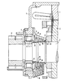
- an annular edge 9 extending parallel to the bearing collar 7 of the cylindrical roller bearing 4 is formed on the body of the labyrinth seal 8.
- the axial extent of the labyrinth seal 8 is dimensioned such that the ring edge 9 forms a narrow radial entry gap 10 together with the bearing collar 7.
- an oil collecting channel 11 is formed on the outer circumference of the body of the labyrinth seal 8, in which oil which has been thrown out from the bearing collar 7 collects and flows off downwards.
- This oil collecting groove 11 results in a relatively long axial gap 12 in the inlet area of the labyrinth seal 8, which makes it difficult for the oil to pass through.
- a first chamber 13 is provided in the body of the labyrinth seal 8, to which a first step 14 of the shaft 3 is assigned.
- the shaft step 14 forms a spraying edge through which oil that has penetrated up to it is thrown off into the first chamber 13. From the walls of this chamber 13, the oil flows through a drain opening 15 to a collecting channel 16.
- This collecting duct 16 opens into the space of a gear housing connected to the motor housing, which is not shown in the drawing. Only the pinion 17 connected to the shaft 3 is shown by the transmission.
- a second chamber 18 and then further chambers 19 are formed axially spaced apart from the first chamber 13 in the body of the labyrinth seal 8.
- a second gradation 20 of the shaft 3 is assigned to the second chamber 19. No further shaft gradations are provided in the area of the further chamber 19. However, it is also possible to apply gradations to the shaft 3 in this area.
- the outlet gap 21 of the labyrinth seal 8 is formed between an axially projecting rim 22 formed on the body of the labyrinth seal 8 and the one end face 23 of the rotor 2.
- the outlet gap 21 ends at the same diameter as the inlet gap 10. This avoids pressure differences between the inlet and outlet sides of the labyrinth seal 8 and thus achieves a largely conveyance-neutral labyrinth.
Landscapes
- Engineering & Computer Science (AREA)
- General Engineering & Computer Science (AREA)
- Mechanical Engineering (AREA)
- Sealing Using Fluids, Sealing Without Contact, And Removal Of Oil (AREA)
- Packages (AREA)
- Rolling Contact Bearings (AREA)
- Motor Or Generator Frames (AREA)
- Seal Device For Vehicle (AREA)
Applications Claiming Priority (2)
| Application Number | Priority Date | Filing Date | Title |
|---|---|---|---|
| DE4029990 | 1990-09-21 | ||
| DE4029990 | 1990-09-21 |
Publications (2)
| Publication Number | Publication Date |
|---|---|
| EP0476476A1 true EP0476476A1 (fr) | 1992-03-25 |
| EP0476476B1 EP0476476B1 (fr) | 1994-11-30 |
Family
ID=6414730
Family Applications (1)
| Application Number | Title | Priority Date | Filing Date |
|---|---|---|---|
| EP91115191A Expired - Lifetime EP0476476B1 (fr) | 1990-09-21 | 1991-09-09 | Joint d'étanchéité |
Country Status (5)
| Country | Link |
|---|---|
| EP (1) | EP0476476B1 (fr) |
| AT (1) | ATE114793T1 (fr) |
| DE (1) | DE59103663D1 (fr) |
| ES (1) | ES2064843T3 (fr) |
| PT (1) | PT99017B (fr) |
Cited By (7)
| Publication number | Priority date | Publication date | Assignee | Title |
|---|---|---|---|---|
| EP0656680A1 (fr) * | 1993-12-01 | 1995-06-07 | General Electric Company | Palier de sortie pour moteur de traction à courant alternatif utilisé dans une locomotive |
| US5611546A (en) * | 1994-05-17 | 1997-03-18 | Siemens Aktiengesellschaft | Labyrinth seal having a pressure inducing fan means |
| DE19844417C1 (de) * | 1998-09-28 | 2000-05-11 | Siemens Ag | Gehäusegestaltung zur Abdichtung eines Zahnradschutz- oder Getriebekastens |
| CN1061747C (zh) * | 1996-08-26 | 2001-02-07 | 周贵留 | 浮动机械密封装置 |
| DE10322027A1 (de) * | 2003-05-16 | 2004-12-16 | Siemens Ag | Bahnantrieb mit Dichtungsanordnung |
| EP3358207A1 (fr) * | 2017-02-07 | 2018-08-08 | Siemens Aktiengesellschaft | Arbre avec un bord destiné à évacuer par action centrifuge un lubrifiant s'introduisant le long de l'arbre |
| DE102020129444A1 (de) | 2020-11-09 | 2022-05-12 | Bayerische Motoren Werke Aktiengesellschaft | Elektrische Maschine für ein Kraftfahrzeug, insbesondere für einen Kraftwagen, sowie Kraftfahrzeug mit wenigstens einer solchen elektrischen Maschine |
Families Citing this family (1)
| Publication number | Priority date | Publication date | Assignee | Title |
|---|---|---|---|---|
| FR3141211B1 (fr) * | 2022-10-25 | 2025-01-31 | Safran Aircraft Engines | Ensemble pour une turbomachine |
Citations (1)
| Publication number | Priority date | Publication date | Assignee | Title |
|---|---|---|---|---|
| DE1475600A1 (de) * | 1965-08-03 | 1969-01-16 | Krupp Gmbh | Wellendichtung |
-
1991
- 1991-09-09 AT AT91115191T patent/ATE114793T1/de not_active IP Right Cessation
- 1991-09-09 DE DE59103663T patent/DE59103663D1/de not_active Expired - Lifetime
- 1991-09-09 EP EP91115191A patent/EP0476476B1/fr not_active Expired - Lifetime
- 1991-09-09 ES ES91115191T patent/ES2064843T3/es not_active Expired - Lifetime
- 1991-09-20 PT PT99017A patent/PT99017B/pt not_active IP Right Cessation
Patent Citations (1)
| Publication number | Priority date | Publication date | Assignee | Title |
|---|---|---|---|---|
| DE1475600A1 (de) * | 1965-08-03 | 1969-01-16 | Krupp Gmbh | Wellendichtung |
Non-Patent Citations (1)
| Title |
|---|
| KONSTRUKTION, Band 39, Nr. 3, März 1987, Seiten 107-113, Berlin, DE; W. HAAS et al.: "Berührungsfreie Wellendichtungen für flüssigkeitsbespritzte Dichtstellen" * |
Cited By (9)
| Publication number | Priority date | Publication date | Assignee | Title |
|---|---|---|---|---|
| EP0656680A1 (fr) * | 1993-12-01 | 1995-06-07 | General Electric Company | Palier de sortie pour moteur de traction à courant alternatif utilisé dans une locomotive |
| US5611546A (en) * | 1994-05-17 | 1997-03-18 | Siemens Aktiengesellschaft | Labyrinth seal having a pressure inducing fan means |
| CN1061747C (zh) * | 1996-08-26 | 2001-02-07 | 周贵留 | 浮动机械密封装置 |
| DE19844417C1 (de) * | 1998-09-28 | 2000-05-11 | Siemens Ag | Gehäusegestaltung zur Abdichtung eines Zahnradschutz- oder Getriebekastens |
| DE10322027A1 (de) * | 2003-05-16 | 2004-12-16 | Siemens Ag | Bahnantrieb mit Dichtungsanordnung |
| DE10322027B4 (de) * | 2003-05-16 | 2013-03-07 | Siemens Aktiengesellschaft | Bahnantrieb mit Dichtungsanordnung |
| EP3358207A1 (fr) * | 2017-02-07 | 2018-08-08 | Siemens Aktiengesellschaft | Arbre avec un bord destiné à évacuer par action centrifuge un lubrifiant s'introduisant le long de l'arbre |
| WO2018145789A1 (fr) * | 2017-02-07 | 2018-08-16 | Siemens Aktiengesellschaft | Arbre doté d'un bord de projection servant à évacuer du lubrifiant pénétrant le long d'un arbre par la force centrifuge |
| DE102020129444A1 (de) | 2020-11-09 | 2022-05-12 | Bayerische Motoren Werke Aktiengesellschaft | Elektrische Maschine für ein Kraftfahrzeug, insbesondere für einen Kraftwagen, sowie Kraftfahrzeug mit wenigstens einer solchen elektrischen Maschine |
Also Published As
| Publication number | Publication date |
|---|---|
| EP0476476B1 (fr) | 1994-11-30 |
| ATE114793T1 (de) | 1994-12-15 |
| PT99017A (pt) | 1993-10-29 |
| ES2064843T3 (es) | 1995-02-01 |
| DE59103663D1 (de) | 1995-01-12 |
| PT99017B (pt) | 1999-02-26 |
Similar Documents
| Publication | Publication Date | Title |
|---|---|---|
| EP1261820B1 (fr) | Garniture d'etancheite en forme de labyrinthe placee entre des pieces rotatives | |
| DE3914175C2 (fr) | ||
| DE10044615A1 (de) | Entlüftungsvorrichtung für ein Kurbelgehäuse | |
| DE102017103548A1 (de) | Antriebsvorrichtung | |
| DE2932728C2 (de) | Rotationskolbenmaschine, insbesondere Motor | |
| EP1903231A2 (fr) | Joint de roulement d'arbre | |
| WO2019037806A1 (fr) | Système de recouvrement pour arbres d'essieu monté de véhicules ferroviaires | |
| EP0476476B1 (fr) | Joint d'étanchéité | |
| WO2020074422A1 (fr) | Transmission d'essieu monté à joint d'étanchéité | |
| EP0282755B1 (fr) | Moteur à manchon d'entrefer | |
| DE102014011228B4 (de) | Elektrische Maschine | |
| DE69103252T2 (de) | Dichtungsanordnung für Lagerung einer Maschine, insbesondere für Turbomaschine. | |
| DE102021002931A1 (de) | Getriebe mit einer Welle, zumindest einem ersten Lager, einem Gehäuseteil und einem Deckel | |
| WO2016198067A1 (fr) | Système de générateur pour véhicules ferroviaires | |
| WO2023094501A1 (fr) | Dispositif de rotor pour une machine électrique et machine électrique dotée de ce dispositif de rotor | |
| DE19548471C1 (de) | Umwälzpumpenaggregat | |
| DE102019131779A1 (de) | Elektrischer Nockenwellenversteller mit verbesserter Nockenwellenanbindung sowie Verfahren zum Herstellen des Nockenwellenverstellers | |
| DE9216772U1 (de) | Antriebsaggregat | |
| DE4326627B4 (de) | Flügelzellenpumpe | |
| DE3931988A1 (de) | Spaltrohrmotor | |
| DE68905027T2 (de) | Mehrstufige roots-pumpe und deren montageverfahren. | |
| DE2402283C3 (de) | Hydrostatische Pumpe bzw. hydrostatischer Motor | |
| DE10213950B4 (de) | Hydrodynamische Kupplung, insbesondere Drehmomentwandler | |
| DE4215463A1 (de) | Rüttler mit eingebautem Elektromotor | |
| DE2721385C2 (fr) |
Legal Events
| Date | Code | Title | Description |
|---|---|---|---|
| PUAI | Public reference made under article 153(3) epc to a published international application that has entered the european phase |
Free format text: ORIGINAL CODE: 0009012 |
|
| AK | Designated contracting states |
Kind code of ref document: A1 Designated state(s): AT CH DE ES FR GB LI |
|
| 17P | Request for examination filed |
Effective date: 19920508 |
|
| 17Q | First examination report despatched |
Effective date: 19940215 |
|
| GRAA | (expected) grant |
Free format text: ORIGINAL CODE: 0009210 |
|
| AK | Designated contracting states |
Kind code of ref document: B1 Designated state(s): AT CH DE ES FR GB LI |
|
| REF | Corresponds to: |
Ref document number: 114793 Country of ref document: AT Date of ref document: 19941215 Kind code of ref document: T |
|
| REF | Corresponds to: |
Ref document number: 59103663 Country of ref document: DE Date of ref document: 19950112 |
|
| GBT | Gb: translation of ep patent filed (gb section 77(6)(a)/1977) |
Effective date: 19941228 |
|
| REG | Reference to a national code |
Ref country code: ES Ref legal event code: FG2A Ref document number: 2064843 Country of ref document: ES Kind code of ref document: T3 |
|
| ET | Fr: translation filed | ||
| PLBE | No opposition filed within time limit |
Free format text: ORIGINAL CODE: 0009261 |
|
| STAA | Information on the status of an ep patent application or granted ep patent |
Free format text: STATUS: NO OPPOSITION FILED WITHIN TIME LIMIT |
|
| 26N | No opposition filed | ||
| REG | Reference to a national code |
Ref country code: GB Ref legal event code: IF02 |
|
| PGFP | Annual fee paid to national office [announced via postgrant information from national office to epo] |
Ref country code: GB Payment date: 20020910 Year of fee payment: 12 |
|
| PGFP | Annual fee paid to national office [announced via postgrant information from national office to epo] |
Ref country code: FR Payment date: 20020930 Year of fee payment: 12 |
|
| PG25 | Lapsed in a contracting state [announced via postgrant information from national office to epo] |
Ref country code: GB Free format text: LAPSE BECAUSE OF NON-PAYMENT OF DUE FEES Effective date: 20030909 |
|
| PGFP | Annual fee paid to national office [announced via postgrant information from national office to epo] |
Ref country code: ES Payment date: 20030912 Year of fee payment: 13 |
|
| GBPC | Gb: european patent ceased through non-payment of renewal fee |
Effective date: 20030909 |
|
| PG25 | Lapsed in a contracting state [announced via postgrant information from national office to epo] |
Ref country code: FR Free format text: LAPSE BECAUSE OF NON-PAYMENT OF DUE FEES Effective date: 20040528 |
|
| REG | Reference to a national code |
Ref country code: FR Ref legal event code: ST |
|
| PG25 | Lapsed in a contracting state [announced via postgrant information from national office to epo] |
Ref country code: ES Free format text: LAPSE BECAUSE OF NON-PAYMENT OF DUE FEES Effective date: 20040910 |
|
| REG | Reference to a national code |
Ref country code: ES Ref legal event code: FD2A Effective date: 20040910 |
|
| PGFP | Annual fee paid to national office [announced via postgrant information from national office to epo] |
Ref country code: CH Payment date: 20061207 Year of fee payment: 16 |
|
| PGFP | Annual fee paid to national office [announced via postgrant information from national office to epo] |
Ref country code: AT Payment date: 20070809 Year of fee payment: 17 |
|
| REG | Reference to a national code |
Ref country code: CH Ref legal event code: PL |
|
| PG25 | Lapsed in a contracting state [announced via postgrant information from national office to epo] |
Ref country code: CH Free format text: LAPSE BECAUSE OF NON-PAYMENT OF DUE FEES Effective date: 20070930 Ref country code: LI Free format text: LAPSE BECAUSE OF NON-PAYMENT OF DUE FEES Effective date: 20070930 |
|
| PG25 | Lapsed in a contracting state [announced via postgrant information from national office to epo] |
Ref country code: AT Free format text: LAPSE BECAUSE OF NON-PAYMENT OF DUE FEES Effective date: 20080909 |
|
| PGFP | Annual fee paid to national office [announced via postgrant information from national office to epo] |
Ref country code: DE Payment date: 20091120 Year of fee payment: 19 |
|
| REG | Reference to a national code |
Ref country code: DE Ref legal event code: R119 Ref document number: 59103663 Country of ref document: DE Effective date: 20110401 |
|
| PG25 | Lapsed in a contracting state [announced via postgrant information from national office to epo] |
Ref country code: DE Free format text: LAPSE BECAUSE OF NON-PAYMENT OF DUE FEES Effective date: 20110401 |