EP0476482A1 - Sensor für eine physische Grösse - Google Patents
Sensor für eine physische Grösse Download PDFInfo
- Publication number
- EP0476482A1 EP0476482A1 EP91115236A EP91115236A EP0476482A1 EP 0476482 A1 EP0476482 A1 EP 0476482A1 EP 91115236 A EP91115236 A EP 91115236A EP 91115236 A EP91115236 A EP 91115236A EP 0476482 A1 EP0476482 A1 EP 0476482A1
- Authority
- EP
- European Patent Office
- Prior art keywords
- support
- frame
- mass
- sensor according
- integral
- Prior art date
- Legal status (The legal status is an assumption and is not a legal conclusion. Google has not performed a legal analysis and makes no representation as to the accuracy of the status listed.)
- Granted
Links
- 238000005259 measurement Methods 0.000 claims abstract description 12
- 238000013016 damping Methods 0.000 claims abstract description 8
- 238000001514 detection method Methods 0.000 claims description 6
- 230000001133 acceleration Effects 0.000 abstract description 6
- 230000000712 assembly Effects 0.000 description 3
- 238000000429 assembly Methods 0.000 description 3
- 230000000295 complement effect Effects 0.000 description 2
- 230000006355 external stress Effects 0.000 description 2
- 238000004519 manufacturing process Methods 0.000 description 2
- 210000000056 organ Anatomy 0.000 description 2
- 239000010453 quartz Substances 0.000 description 2
- VYPSYNLAJGMNEJ-UHFFFAOYSA-N silicon dioxide Inorganic materials O=[Si]=O VYPSYNLAJGMNEJ-UHFFFAOYSA-N 0.000 description 2
- 238000012550 audit Methods 0.000 description 1
- 230000000694 effects Effects 0.000 description 1
- 239000012530 fluid Substances 0.000 description 1
- 230000010365 information processing Effects 0.000 description 1
- 239000007788 liquid Substances 0.000 description 1
- 239000000463 material Substances 0.000 description 1
- 239000002184 metal Substances 0.000 description 1
- 230000003071 parasitic effect Effects 0.000 description 1
- 238000000053 physical method Methods 0.000 description 1
- 229920002050 silicone resin Polymers 0.000 description 1
- 230000035882 stress Effects 0.000 description 1
Images

Classifications
-
- G—PHYSICS
- G01—MEASURING; TESTING
- G01P—MEASURING LINEAR OR ANGULAR SPEED, ACCELERATION, DECELERATION, OR SHOCK; INDICATING PRESENCE, ABSENCE, OR DIRECTION, OF MOVEMENT
- G01P3/00—Measuring linear or angular speed; Measuring differences of linear or angular speeds
- G01P3/02—Devices characterised by the use of mechanical means
- G01P3/16—Devices characterised by the use of mechanical means by using centrifugal forces of solid masses
-
- G—PHYSICS
- G01—MEASURING; TESTING
- G01P—MEASURING LINEAR OR ANGULAR SPEED, ACCELERATION, DECELERATION, OR SHOCK; INDICATING PRESENCE, ABSENCE, OR DIRECTION, OF MOVEMENT
- G01P15/00—Measuring acceleration; Measuring deceleration; Measuring shock, i.e. sudden change of acceleration
- G01P15/02—Measuring acceleration; Measuring deceleration; Measuring shock, i.e. sudden change of acceleration by making use of inertia forces using solid seismic masses
- G01P15/08—Measuring acceleration; Measuring deceleration; Measuring shock, i.e. sudden change of acceleration by making use of inertia forces using solid seismic masses with conversion into electric or magnetic values
- G01P15/097—Measuring acceleration; Measuring deceleration; Measuring shock, i.e. sudden change of acceleration by making use of inertia forces using solid seismic masses with conversion into electric or magnetic values by vibratory elements
-
- G—PHYSICS
- G01—MEASURING; TESTING
- G01D—MEASURING NOT SPECIALLY ADAPTED FOR A SPECIFIC VARIABLE; ARRANGEMENTS FOR MEASURING TWO OR MORE VARIABLES NOT COVERED IN A SINGLE OTHER SUBCLASS; TARIFF METERING APPARATUS; MEASURING OR TESTING NOT OTHERWISE PROVIDED FOR
- G01D11/00—Component parts of measuring arrangements not specially adapted for a specific variable
- G01D11/24—Housings ; Casings for instruments
- G01D11/245—Housings for sensors
-
- G—PHYSICS
- G01—MEASURING; TESTING
- G01P—MEASURING LINEAR OR ANGULAR SPEED, ACCELERATION, DECELERATION, OR SHOCK; INDICATING PRESENCE, ABSENCE, OR DIRECTION, OF MOVEMENT
- G01P1/00—Details of instruments
- G01P1/02—Housings
- G01P1/023—Housings for acceleration measuring devices
-
- G—PHYSICS
- G01—MEASURING; TESTING
- G01P—MEASURING LINEAR OR ANGULAR SPEED, ACCELERATION, DECELERATION, OR SHOCK; INDICATING PRESENCE, ABSENCE, OR DIRECTION, OF MOVEMENT
- G01P15/00—Measuring acceleration; Measuring deceleration; Measuring shock, i.e. sudden change of acceleration
- G01P15/02—Measuring acceleration; Measuring deceleration; Measuring shock, i.e. sudden change of acceleration by making use of inertia forces using solid seismic masses
- G01P15/08—Measuring acceleration; Measuring deceleration; Measuring shock, i.e. sudden change of acceleration by making use of inertia forces using solid seismic masses with conversion into electric or magnetic values
- G01P2015/0805—Measuring acceleration; Measuring deceleration; Measuring shock, i.e. sudden change of acceleration by making use of inertia forces using solid seismic masses with conversion into electric or magnetic values being provided with a particular type of spring-mass-system for defining the displacement of a seismic mass due to an external acceleration
- G01P2015/0822—Measuring acceleration; Measuring deceleration; Measuring shock, i.e. sudden change of acceleration by making use of inertia forces using solid seismic masses with conversion into electric or magnetic values being provided with a particular type of spring-mass-system for defining the displacement of a seismic mass due to an external acceleration for defining out-of-plane movement of the mass
- G01P2015/0825—Measuring acceleration; Measuring deceleration; Measuring shock, i.e. sudden change of acceleration by making use of inertia forces using solid seismic masses with conversion into electric or magnetic values being provided with a particular type of spring-mass-system for defining the displacement of a seismic mass due to an external acceleration for defining out-of-plane movement of the mass for one single degree of freedom of movement of the mass
- G01P2015/0828—Measuring acceleration; Measuring deceleration; Measuring shock, i.e. sudden change of acceleration by making use of inertia forces using solid seismic masses with conversion into electric or magnetic values being provided with a particular type of spring-mass-system for defining the displacement of a seismic mass due to an external acceleration for defining out-of-plane movement of the mass for one single degree of freedom of movement of the mass the mass being of the paddle type being suspended at one of its longitudinal ends
Definitions
- the invention relates to a sensor for measuring a physical quantity. More particularly, it relates to a sensor provided with a support which is elastically deformable under the effect of an external stress, such as for example an acceleration, and which is in particular intended to receive detection means sensitive to this stress.
- an external stress such as for example an acceleration
- these sensors comprise a deformable support which has the general shape of a beam of rectangular section, this beam being fixed in overhang on a frame.
- This deformable support which is designed to flex along at least one sensitive axis, under the action of external stress, comprises a transducer.
- This transducer is fixed on a large face of the deformable support, equidistant from one or the other of its ends.
- the transducer which is for example constituted by a quartz resonator in the form of a double tuning fork, sends information in the form of a frequency variation, to an information processing circuit.
- the transducer which is for example constituted by a quartz resonator in the form of a double tuning fork, sends information in the form of a frequency variation, to an information processing circuit.
- one or more other transducers are often used.
- the beam has at its free end a mass which, under the action of acceleration, moves by deforming the support.
- a particularly economical solution consists in placing the mass in a housing integral with the frame to form a pneumatic damping by passage of a fluid between two chambers formed in this housing.
- the invention aims to remedy this drawback by providing a physical measurement sensor whose beam provided with its mass can be precisely mounted to provide reliable operation, despite an extremely small clearance between the mass and the housing in which it is intended to move.
- the positioning means are at least partially secured to the support.
- the positioning means comprise two relatively distant orifice (s) -tenon (s) assemblies, each of these assemblies being formed, on the one hand, in the support, and on the other hand, in the built.
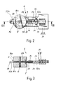
- FIG. 1 there is seen a preferred embodiment of the measurement sensor according to the invention, designated by the general reference numeral 1.
- This sensor 1 comprises a frame 2 which consists of two shells respectively 2a and 2b having a similar shape and intended to be assembled by means of fixing means, such as screws 4, only one of which has been shown here.
- the frame 2 is shaped to receive a functional unit 6 which comprises a support 8 which is elastically deformable under the action of a physical quantity to be captured or measured.
- the axis 12 crosses on both sides the support 8 which is sandwiched between the two half-masses 10a and 10b.
- the support 8 further comprises two detection means 14 constituted, in the example shown, by two quartz resonators in the form of double tuning fork mounted on either side of the support 8.
- Each resonator 14 is electrically connected to a corresponding printed circuit board 16 on which are mounted electronic components 18 of which only one has been shown here.
- the elements 16 and 18 constitute an electronic circuit 20.
- the resonators 14 are connected in oscillating circuits, not referenced, whose resonant frequencies vary according to the deformation of the support 8.
- the oscillating circuits therefore deliver signals which are processed and analyzed in the electronic circuit 20.
- the latter delivers a variable signal as a function of the deformation of the support 8 and therefore, in this example, of the acceleration undergone by the two half-masses 10a and 10b.
- two printed circuit boards 16 are therefore provided, arranged on either side of the support 8 and fixed on the latter by means of driven pins 19 or other similar means, such as screws, not shown.
- the support 8 comprises, under each of its detection means or resonator 14, a through opening 22 allowing each resonator to vibrate freely.
- the support 8 comprises a base 24 which is intended to be mechanically fixed to the frame 2. From this base 24 extends a member 26 of generally elongated shape which is particularly capable of deforming elastically relative to the base 24.
- This elongated member has the shape of a beam of rectangular section fixed, in this example, overhanging on the frame 2.
- the base 24 further comprises a passage orifice 25 for fixing the support 8 on the lower shell 2b of the frame 2.
- This fixing orifice 25 is intended to receive a screw 27 which engages directly in a threaded bore 29 formed in the shell 2b of the frame 2.
- a flange 23 which is held in abutment on the base 24 to coincide with the edge of which the elongated member or beam 26 projects.
- the measurement sensor according to the invention further comprises damping means constituted by blind housings 30a and 30b formed respectively in the shell 2a and in the shell 2b of the frame 2.
- the housings 30a and 30b are intended to receive respectively the 'one of the two half-masses 10a, 10b which in particular each have a shape complementary to that of the corresponding housing.
- the housings 30a and 30b have a complementary periphery.
- a small clearance is provided between the outer periphery of the mass and the inner wall of the housing, of the order of 0.1 mm (0.1 ′ 10- 3 meters).
- the measurement sensor 1 comprises positioning means 32 of the mass in each housing 30a, 30b.
- the positioning means 32 are at least partially integral with the support 8 and they comprise two sets of tenon (s) 32a - orifice (s) 32b, 32c relatively distant, each of these sets being formed, on the one hand, in the frame 2, and on the other hand, in the support 8.
- the two positioning means 32 are formed on a positioning axis X1, coincident with the longitudinal axis of the beam 26.
- the tenons 32a are driven into corresponding orifices 32c formed in the shell 2b of the frame 2, while two other orifices 32b, which are each intended to receive one of the tenons 32a, are formed in the support 8.
- Two other orifices, not shown and not referenced, identical to the orifices 32c, are formed in the shell 2a of the frame 2 to receive the free ends of the two tenons 32a.
- the holes in the shell 2a are positioned so that they coincide axially ment with those of the shell 2b when these two shells 2a and 2b are assembled one on the other.
- the two shells 2a and 2b are of identical shape.
- the two studs 32a can be driven directly into the orifices 32b formed in the support 8. In other embodiments not shown, these studs can come in one piece, either with one of the two shells 2a or 2b, either with support 8.
- each assembly comprises a stud which is formed by two protuberances coming integrally with the support, extending coaxially on either side of it and which cooperates with two orifices respectively arranged in the lower and upper shells of the support.
- each assembly comprises two studs coming respectively from one material with one of the shells of the frame and mounted opposite one another in a coaxial manner by engaging in the orifice formed in the support. For each set, two pins and a single orifice are provided in this variant.
- a first set of tenon (s) 32a - orifice (s) 32b is integral with the base 24, while a second assembly is integral with two extensions 34 extending from the base 24.
- the two extensions 34 have the form of arms which extend parallel to the beam 26 in the direction of the free end thereof. The two arms 34 therefore extend on either side of the beam 26, substantially in the same plane, and they meet beyond the free end of this beam to form around it a frame of positioning.
- the support 8 may comprise only one arm 34 suitably pierced at its free end by a through orifice forming the positioning orifice 32b.
- the two arms 34 are linked together by means of an upright 36 forming a junction between the two arms 34 which meet in the vicinity and beyond the free end of the beam 26
- This junction upright 36 has a protuberance 38 in which the positioning orifice 32b is directly formed.
- the second set of tenon (s) 32a - orifice (s) 32b is formed in the joining amount 36 of the two arms 34. Therefore, since the arms 34 like the orifices 32b, the amount 36 and the protuberance 38 are integrally formed in the support 8, the positioning means, which moreover comprise the pins 32a and the corresponding orifices 32c formed in the shells 2a and 2b, are at least partially integral with the support 8 and therefore with the beam 26.
- the two arms or extensions 34 and the upright 36 are partially housed in a space E left between the two half-masses 10a and 10b.
- these two arms 34 and the upright 36 extending between and under the two half-masses 10a and 10b occupy a minimum space and do not increase the size of the sensor according to the invention.
- the support 8 provided with its positioning means is produced in a single piece obtained by stamping, for example cold, so that the positioning means according to the invention, and in particular the arms 34, the junction upright 36 and the orifices 32b are preferably obtained in a single manufacturing step and simultaneously with the production of the beam 26, associated with its base 24. It will be noted that the support 8 can therefore be easily cut from a metal strip, continuously.
- a seal is housed in a groove 50, produced for example in the shell 2b.
- a liquid seal such as a silicone resin.
Landscapes
- Physics & Mathematics (AREA)
- General Physics & Mathematics (AREA)
- Pressure Sensors (AREA)
- Motorcycle And Bicycle Frame (AREA)
- Measurement Of Mechanical Vibrations Or Ultrasonic Waves (AREA)
- Measuring Fluid Pressure (AREA)
Applications Claiming Priority (2)
| Application Number | Priority Date | Filing Date | Title |
|---|---|---|---|
| FR9011530 | 1990-09-17 | ||
| FR9011530A FR2666888B1 (fr) | 1990-09-17 | 1990-09-17 | Capteur de mesure d'une grandeur physique. |
Publications (2)
| Publication Number | Publication Date |
|---|---|
| EP0476482A1 true EP0476482A1 (de) | 1992-03-25 |
| EP0476482B1 EP0476482B1 (de) | 1995-01-25 |
Family
ID=9400431
Family Applications (1)
| Application Number | Title | Priority Date | Filing Date |
|---|---|---|---|
| EP91115236A Expired - Lifetime EP0476482B1 (de) | 1990-09-17 | 1991-09-10 | Sensor für eine physische Grösse |
Country Status (6)
| Country | Link |
|---|---|
| US (1) | US5239866A (de) |
| EP (1) | EP0476482B1 (de) |
| JP (1) | JPH04297837A (de) |
| KR (1) | KR920006744A (de) |
| DE (1) | DE69106987D1 (de) |
| FR (1) | FR2666888B1 (de) |
Cited By (3)
| Publication number | Priority date | Publication date | Assignee | Title |
|---|---|---|---|---|
| GB2231965B (en) * | 1989-05-24 | 1994-02-16 | Mitsubishi Electric Corp | Piezoelectric accelerometer for automobiles |
| DE4332944A1 (de) * | 1993-09-28 | 1995-03-30 | Bosch Gmbh Robert | Sensor mit einer Quarz-Stimmgabel |
| EP0624385A3 (de) * | 1993-05-10 | 1997-06-25 | Siemens Ag | Implantierbare, durch den Rhythmus gesteuerte Reizungsvorrichtung mit einem Miniatur-Hybrid-Aktivitätsensor. |
Families Citing this family (11)
| Publication number | Priority date | Publication date | Assignee | Title |
|---|---|---|---|---|
| US5342017A (en) * | 1992-09-30 | 1994-08-30 | Cincinnati Milacron Inc. | Damped cantilevered support arm assembly |
| JP3387199B2 (ja) * | 1994-04-21 | 2003-03-17 | 松下電器産業株式会社 | 角速度センサ装置 |
| EP0693690B1 (de) * | 1994-06-29 | 1999-04-28 | New Sd, Inc. | Beschleunigungsmesser sowie Verfahren zu seiner Herstellung |
| US6453746B1 (en) * | 2000-06-07 | 2002-09-24 | Sandia Corporation | Microscale acceleration history discriminators |
| JP2002296370A (ja) * | 2001-03-30 | 2002-10-09 | Seiko Precision Inc | メトロノーム用振り子 |
| US6925883B2 (en) * | 2003-08-28 | 2005-08-09 | United Technologies Corporation | Non resonating close coupled probe |
| CN102121829B (zh) | 2010-08-09 | 2013-06-12 | 汪滔 | 一种微型惯性测量系统 |
| CN102980584B (zh) * | 2011-09-02 | 2017-12-19 | 深圳市大疆创新科技有限公司 | 一种无人飞行器惯性测量模块 |
| JP6188020B2 (ja) * | 2013-06-21 | 2017-08-30 | 国立大学法人名古屋大学 | 水晶振動子を用いた荷重センサ |
| CN106030245B (zh) | 2014-04-25 | 2019-11-15 | 深圳市大疆创新科技有限公司 | 惯性传感装置 |
| WO2016161562A1 (en) | 2015-04-07 | 2016-10-13 | SZ DJI Technology Co., Ltd. | System and method for providing a simple and reliable inertia measurement unit (imu) |
Citations (2)
| Publication number | Priority date | Publication date | Assignee | Title |
|---|---|---|---|---|
| GB2176607A (en) * | 1985-06-18 | 1986-12-31 | Standard Telephones Cables Ltd | Accelerometer device |
| EP0373040A1 (de) * | 1988-12-02 | 1990-06-13 | Societe D'applications Generales D'electricite Et De Mecanique Sagem | Kraft-Frequenz-Messwandler mit schwingenden Balken und dessen Verwendung in einem schwingenden Beschleunigungsmesser |
Family Cites Families (12)
| Publication number | Priority date | Publication date | Assignee | Title |
|---|---|---|---|---|
| DE1817946A1 (de) * | 1968-12-24 | 1974-10-31 | Toyota Central Res & Dev | Geraet zur messung von beschleunigungskomponenten |
| US4032733A (en) * | 1975-10-06 | 1977-06-28 | Meisenheimer Jr Daniel Thomas | Omnidirectional inertia switch |
| DE2556298C2 (de) * | 1975-12-13 | 1982-05-13 | Messerschmitt-Bölkow-Blohm GmbH, 8000 München | Piezoelektrischer Beschleunigungsgeber |
| US4091885A (en) * | 1976-08-30 | 1978-05-30 | Advance Weight Systems, Inc. | Weight sensing apparatus |
| JPS6034433B2 (ja) * | 1977-03-07 | 1985-08-08 | 株式会社豊田中央研究所 | 超音波変換器 |
| US4188612A (en) * | 1978-05-01 | 1980-02-12 | Teledyne Industries Inc. (Geotech Division) | Piezoelectric seismometer |
| FR2452714A1 (fr) * | 1979-03-30 | 1980-10-24 | Thomson Csf | Accelerometre a ondes elastiques |
| US4393950A (en) * | 1981-06-26 | 1983-07-19 | Triangle Package Machinery Company | Tare weighing apparatus and method therefor |
| US4811604A (en) * | 1986-05-23 | 1989-03-14 | British Aerospace Public Limited Company | Accelerometers |
| US4872342A (en) * | 1986-06-27 | 1989-10-10 | Sundstrand Data Control, Inc. | Translational accelerometer and accelerometer assembly method |
| US4882933A (en) * | 1988-06-03 | 1989-11-28 | Novasensor | Accelerometer with integral bidirectional shock protection and controllable viscous damping |
| US5017743A (en) * | 1990-03-09 | 1991-05-21 | Trw Technar Inc. | Gas damped deceleration switch |
-
1990
- 1990-09-17 FR FR9011530A patent/FR2666888B1/fr not_active Expired - Fee Related
-
1991
- 1991-09-05 KR KR1019910015491A patent/KR920006744A/ko not_active Withdrawn
- 1991-09-10 EP EP91115236A patent/EP0476482B1/de not_active Expired - Lifetime
- 1991-09-10 DE DE69106987T patent/DE69106987D1/de not_active Expired - Lifetime
- 1991-09-13 JP JP3261372A patent/JPH04297837A/ja active Pending
- 1991-09-16 US US07/760,395 patent/US5239866A/en not_active Expired - Fee Related
Patent Citations (2)
| Publication number | Priority date | Publication date | Assignee | Title |
|---|---|---|---|---|
| GB2176607A (en) * | 1985-06-18 | 1986-12-31 | Standard Telephones Cables Ltd | Accelerometer device |
| EP0373040A1 (de) * | 1988-12-02 | 1990-06-13 | Societe D'applications Generales D'electricite Et De Mecanique Sagem | Kraft-Frequenz-Messwandler mit schwingenden Balken und dessen Verwendung in einem schwingenden Beschleunigungsmesser |
Cited By (3)
| Publication number | Priority date | Publication date | Assignee | Title |
|---|---|---|---|---|
| GB2231965B (en) * | 1989-05-24 | 1994-02-16 | Mitsubishi Electric Corp | Piezoelectric accelerometer for automobiles |
| EP0624385A3 (de) * | 1993-05-10 | 1997-06-25 | Siemens Ag | Implantierbare, durch den Rhythmus gesteuerte Reizungsvorrichtung mit einem Miniatur-Hybrid-Aktivitätsensor. |
| DE4332944A1 (de) * | 1993-09-28 | 1995-03-30 | Bosch Gmbh Robert | Sensor mit einer Quarz-Stimmgabel |
Also Published As
| Publication number | Publication date |
|---|---|
| KR920006744A (ko) | 1992-04-28 |
| FR2666888B1 (fr) | 1994-04-15 |
| EP0476482B1 (de) | 1995-01-25 |
| FR2666888A1 (fr) | 1992-03-20 |
| JPH04297837A (ja) | 1992-10-21 |
| US5239866A (en) | 1993-08-31 |
| DE69106987D1 (de) | 1995-03-09 |
Similar Documents
| Publication | Publication Date | Title |
|---|---|---|
| EP0476482B1 (de) | Sensor für eine physische Grösse | |
| EP1388175B1 (de) | Gehäuse für einen optischen halbleiter mit eingebetteter linse und abschirmvorrichtung | |
| EP1672443B1 (de) | Uhr mit einem Drucksensor | |
| FR2835654A1 (fr) | Boitier semi-conducteur optique a porte-lentille accouple | |
| WO2002061384A1 (fr) | Capteur de pression et moteur de fusee l"incorporant | |
| FR2616547A1 (fr) | Accelerometre, notamment accelerometre capacitif monte dans un tableau de bord | |
| FR3056978B1 (fr) | Capteur de pression, en particulier microphone a agencement ameliore | |
| FR2874433A1 (fr) | Dispositif a capteur magnetique ayant des composants montes sur un aimant | |
| CH713513B1 (fr) | Module optoélectronique muni d'au moins un circuit photorécepteur. | |
| FR3018990A1 (fr) | Module electronique a element de detecteur integre, pour appareils de commande de boite de vitesses | |
| FR2466931A1 (fr) | Transducteur electro-acoustique directionnel | |
| FR2837921A1 (fr) | Capteur de pression et procede de fabrication de ce dernier | |
| EP0476481B1 (de) | Sensor für eine physische Grösse | |
| EP0014656A1 (de) | Piezoelektrischer Beschleunigungsmesser | |
| FR2769100A1 (fr) | Boitier pour dispositif photosemi-conducteur | |
| EP1431847B1 (de) | Tragbares elektronisches Gerät, insbesondere Uhr, mit einer Antenne, die aus einer Spule mit grossem Diameter gebildet ist | |
| FR3041496A1 (fr) | Capteur acoustique ayant une membrane et un transducteur electroacoustique | |
| FR2629662A1 (fr) | Capsule electroacoustique a bobine rapportee | |
| FR2830120A1 (fr) | Dispositif de fixation pour un detecteur et detecteur associe a un tel dispositif | |
| EP0082767B1 (de) | Verfahren zum Zusammenbau von einem Gerät bestchend aus einem Hochfrequenzhohlraum in dem ein Innenleiter befestigt ist | |
| EP0561677B1 (de) | Resonatur für einen temperaturkompensierten Oszillator mit geringem Energieverbrauch und schneller Aufwärmzeit | |
| FR2872903A1 (fr) | Detecteur de pression du type a detection de pression differentielle et procede pour fabriquer celui-ci | |
| EP0060736B1 (de) | Vorrichtung zum Festhalten einer Skala an einem Gehäuse eines Kilometerzählers oder dergleichen | |
| EP3009812B2 (de) | Modular aufgebaute erfassungsvorrichtung, und diese umfassende industrieausrüstung | |
| FR2772913A1 (fr) | Capteur de mesure d'une grandeur physique |
Legal Events
| Date | Code | Title | Description |
|---|---|---|---|
| PUAI | Public reference made under article 153(3) epc to a published international application that has entered the european phase |
Free format text: ORIGINAL CODE: 0009012 |
|
| AK | Designated contracting states |
Kind code of ref document: A1 Designated state(s): CH DE ES GB IT LI NL SE |
|
| 17P | Request for examination filed |
Effective date: 19920413 |
|
| 17Q | First examination report despatched |
Effective date: 19930915 |
|
| GRAA | (expected) grant |
Free format text: ORIGINAL CODE: 0009210 |
|
| AK | Designated contracting states |
Kind code of ref document: B1 Designated state(s): CH DE ES GB IT LI NL SE |
|
| PG25 | Lapsed in a contracting state [announced via postgrant information from national office to epo] |
Ref country code: IT Free format text: LAPSE BECAUSE OF FAILURE TO SUBMIT A TRANSLATION OF THE DESCRIPTION OR TO PAY THE FEE WITHIN THE PRE;WARNING: LAPSES OF ITALIAN PATENTS WITH EFFECTIVE DATE BEFORE 2007 MAY HAVE OCCURRED AT ANY TIME BEFORE 2007. THE CORRECT EFFECTIVE DATE MAY BE DIFFERENT FROM THE ONE RECORDED.SCRIBED TIME-LIMIT Effective date: 19950125 Ref country code: ES Free format text: THE PATENT HAS BEEN ANNULLED BY A DECISION OF A NATIONAL AUTHORITY Effective date: 19950125 Ref country code: GB Effective date: 19950125 Ref country code: NL Effective date: 19950125 |
|
| REF | Corresponds to: |
Ref document number: 69106987 Country of ref document: DE Date of ref document: 19950309 |
|
| PG25 | Lapsed in a contracting state [announced via postgrant information from national office to epo] |
Ref country code: SE Effective date: 19950425 |
|
| PG25 | Lapsed in a contracting state [announced via postgrant information from national office to epo] |
Ref country code: DE Effective date: 19950426 |
|
| NLV1 | Nl: lapsed or annulled due to failure to fulfill the requirements of art. 29p and 29m of the patents act | ||
| GBV | Gb: ep patent (uk) treated as always having been void in accordance with gb section 77(7)/1977 [no translation filed] |
Effective date: 19950125 |
|
| PG25 | Lapsed in a contracting state [announced via postgrant information from national office to epo] |
Ref country code: CH Effective date: 19950930 Ref country code: LI Effective date: 19950930 |
|
| PLBE | No opposition filed within time limit |
Free format text: ORIGINAL CODE: 0009261 |
|
| STAA | Information on the status of an ep patent application or granted ep patent |
Free format text: STATUS: NO OPPOSITION FILED WITHIN TIME LIMIT |
|
| 26N | No opposition filed | ||
| REG | Reference to a national code |
Ref country code: CH Ref legal event code: PL |