EP0476637B1 - Schalter-gesteuertes zonenartiges Heizkabel und Verfahren - Google Patents
Schalter-gesteuertes zonenartiges Heizkabel und Verfahren Download PDFInfo
- Publication number
- EP0476637B1 EP0476637B1 EP91115902A EP91115902A EP0476637B1 EP 0476637 B1 EP0476637 B1 EP 0476637B1 EP 91115902 A EP91115902 A EP 91115902A EP 91115902 A EP91115902 A EP 91115902A EP 0476637 B1 EP0476637 B1 EP 0476637B1
- Authority
- EP
- European Patent Office
- Prior art keywords
- switch
- heating
- resistive
- electrical
- cable
- Prior art date
- Legal status (The legal status is an assumption and is not a legal conclusion. Google has not performed a legal analysis and makes no representation as to the accuracy of the status listed.)
- Expired - Lifetime
Links
Images


Classifications
-
- H—ELECTRICITY
- H05—ELECTRIC TECHNIQUES NOT OTHERWISE PROVIDED FOR
- H05B—ELECTRIC HEATING; ELECTRIC LIGHT SOURCES NOT OTHERWISE PROVIDED FOR; CIRCUIT ARRANGEMENTS FOR ELECTRIC LIGHT SOURCES, IN GENERAL
- H05B3/00—Ohmic-resistance heating
-
- H—ELECTRICITY
- H05—ELECTRIC TECHNIQUES NOT OTHERWISE PROVIDED FOR
- H05B—ELECTRIC HEATING; ELECTRIC LIGHT SOURCES NOT OTHERWISE PROVIDED FOR; CIRCUIT ARRANGEMENTS FOR ELECTRIC LIGHT SOURCES, IN GENERAL
- H05B3/00—Ohmic-resistance heating
- H05B3/40—Heating elements having the shape of rods or tubes
- H05B3/54—Heating elements having the shape of rods or tubes flexible
- H05B3/56—Heating cables
Definitions
- the present invention relates to electrical heating cables that use thermal switches to regulate zone-type heating elements.
- Flexible, elongated electrical cables have been used commercially for many years for heating pipes, tanks, valves, vessels and for a variety of other applications.
- the heating cables maintain the temperature of fluids in pipes or equipment and prevent freezing.
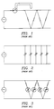
- a constant wattage heater typically comprises two conductors connected to a power supply with a number of resistive elements aligned in parallel with each other and connected to the conductors. Electrical current is supplied to the conductors and passes through the resistive elements to generate heat. Temperature control of a constant wattage heater is generally achieved by means of an external thermostat which delivers or interrupts current to the entire cable based on the temperature of the pipe or the temperature of the cable.
- a constant wattage heater generates heat relatively uniformly along its length in response to a single thermostat control, and has the potential to provide too much heat for certain areas and not enough for others. If the thermostat is not placed in a representative location, the cable may overheat or the fluid may cool below the desired temperature. Further, the high-current controllers used in conjunction with constant wattage heaters may fail in certain high-wattage conditions. Failure of the controller can cause the cable to overheat if failure occurs in the on position, or interrupts heat generation for the entire cable if failure occurs in the off position.
- the second major type of heating cable is the self-limiting or self-regulating type, an example of which is shown schematically in Fig. 2.
- a typical self-regulating heating cable comprises a pair of conductors connected to a power supply and has either a number of discrete positive temperature coefficient (PTC) resistive elements connected in parallel with each other, as shown in Figure 2, or a strip or web of PTC conductive polymer connecting the conductors.
- PTC positive temperature coefficient
- Self-regulating heating cables using PTC materials produce heat until the cable reaches a temperature limit essentially dictated by the switching temperature of the PTC material.
- the switching temperature is that temperature at which the resistance of the material rises sharply, often on the order of several orders of magnitude over a relatively short temperature range.
- the current flowing through the material decreases in response to the increased resistance, limiting the power output and preventing overheating.
- the resistive element's heat output will begin to diminish.
- the rate at which the heat output decreases is a characteristic of the PTC material used. For some materials, the heat output changes only gradually, while for others the change is more abrupt. The current will continue to diminish as the temperature rises, but will never completely terminate. A complete disconnection can only be achieved by cutting off the power supply.
- the PTC material may be used to form the heating element itself.
- the heating element may comprise a PTC conductive polymer strip connected between the conductors.
- the heating element can also be a PTC ceramic chip.
- the PTC material may be connected in series with a heating element having a constant resistance, as shown in Fig. 3.
- the PTC material primarily controls the current to the resistor, and only secondarily acts as a heat producing element.
- the PTC material has a heat producing aspect which affects its performance. The current flow depends upon the temperature of the PTC material, which is influenced by the heating element's output as well as the temperature of its surroundings.
- PTC materials can be subject to hysteresis effects. Some PTC materials behave differently when the cable is heating up than when the cable is cooling down. Consequently, the power on temperature of the cable can significantly differ from the shut off temperature. This disparity is generally undesirable and adds to design and manufacturing difficulties.
- the heating cable of the present invention has a switch to control the current in each heating zone of the cable.
- the switch is a thermally operated ferrite reed switch.
- the switch is connected in series with one or more resistive elements in each heating zone, so that the heating zone delivers full power output when the switch is on and zero power output when the switch is off.
- the state of the switch depends upon its Curie point, the temperature at which the permeability of the ferrite material changes dramatically. When the switch's temperature is above the Curie point, the switch is off. When the switch cools to below the Curie point, the switch turns on and delivers power to the heating zone.
- the switching action provides a square wave, in reference to the shape of the curve which results from graphing power output versus temperature for a particular heating zone.
- the ferrite reed switch operates magnetically and as a function of temperature, independent of current flow or power output.
- the switch itself generally produces negligible heat, unless used in a very high current environment, which is not conventional. Consequently, designing a heating cable with a particular switching temperature independent of power output is greatly simplified.
- the heating cable also includes a number of control points along the length of the cable. As a result, the cable varies the heat generated along its length as required for each particular zone.
- the cable uses a number of low current control devices, instead of a single, less reliable high current controller. Further, by reducing the power directed to any single control device, overheating due to an unlikely component failure is virtually eliminated.
- the heating cable of the present invention further includes an internal control method that functions independent of the heating element.
- the heating element may be any heat producing material that can be controlled by the switch. This substantially broadens the range of acceptable heating element materials.
- the heating cable design is also significantly less susceptible to the disadvantages arising from hysteresis.
- a heating cable designed in accordance with the present invention is not controlled by PTC materials.
- the mechanical switches of the present invention are not subject to hysteresis. Therefore, a heating cable can be easily designed that behaves identically whether the cable is heating up or cooling down.
- a heating element is placed in parallel with the switch so that the power output is switched between two positive levels depending on temperature, not fully on or off. Thus, it reduces switching frequency because the cable does not cool as fast.
- the letter C generally designates the heating cable of the present invention, with the numerical suffix indicating the specific embodiment of the cable C.
- Figure 4 illustrates the first preferred embodiment of a heating cable C1 constructed according to the present invention.
- Two electrical conductors 20 and 22 extend substantially parallel to each other.
- the electrical conductors are preferably 10 gauge to 20 gauge copper wires, but can be any low resistance electrical conductors.
- the electrical conductors 20 and 22 are connected in parallel to provide substantially constant voltage along the length of the cable C1.
- the conductors 20 and 22 are encapsulated in a dielectric insulation material 24.
- the insulation material 24 provides electrical insulation for the conductors 20 and 22 and holds them in position.
- the insulation material 24 may be composed of any flexible dielectric substance as commonly used in heating cables.
- the insulation material 24 is notched at intervals 26, 28 and 30 along its length so that the conductors 20 and 22 are alternately exposed.
- a recess 32 is formed in the surface of the insulation material 24 between the conductors 20 and 22.
- the heating cable of the present invention has a switch to control the current in each heating zone of the cable.
- the switch is a thermally operated reed switch 34, received in the recess 32 in the surface of the insulation material 24.
- the switch's first lead 36 is connected to the first conductor 20 through the notch 28 exposing the conductor 20.
- the first lead 36 is connected to the first conductor 20 by any adequate means known to those skilled in the art, such as solder, splices, bands or staples.
- the second lead 37 of the thermal switch 34 extends over the surface of the insulation material 24.
- the exposed portions of the conductor 20, the switch lead 36 and portions of the switch lead 37 are covered with insulation tape 65 to protect the conductor 20 or switch lead 36 or 37 from contacting any other conductive elements. A portion of the second lead 37 remains exposed to contact the heating element.
- a resistive heating element 38 is helically wound about the insulation material 24.
- the heating element 38 can be composed of many materials having appropriate resistance.
- Nichrome wire is a commonly used resistive material.
- the nichrome wire is wound around a stranded fiberglass core, which assembly is then helically wound about the insulation material 24.
- the heating element could also be a resistive foil such as a copper foil.
- the resistive material could also be composed of conductive thermoplastic material, such as carbon loaded crystalline thermoplastic polymer.
- the conductive compositions of polymer and carbon contain from about 4% to about 30% by weight of electrically conductive carbon black.
- the conductive carbon black is uniformly dispersed throughout the matrix. This material is formed into strands which are helically wrapped.
- the resistive material can be stranded, conductive carbon fibers which are helically wrapped around the insulation material 24.
- the heating element 38 contacts the second conductor 22 where the heating element 38 overlaps the notches 26 and 30 exposing the second conductor 22.
- the heating element 38 contacts the second lead 37 of the switch 34 where it overlaps the second lead 37 on the surface of the insulation material 24.
- the heating element 38 is connected to the second lead 37 by any adequate means known to those skilled in the art, such as solder, splices bands, staples or a mechanical pressure connection.
- the switch 34 and the heating element 38 are thus connected in series between the conductors 20 and 22.
- An overjacket 40 encases the entire assembly to prevent short circuits and for environmental protection.
- the schematic diagram of Fig. 5 shows the equivalent circuit of the heating cable C1 according to the present invention.
- the cable C1 is powered by a voltage source 42 connected to the conductors 20 and 22. Current flows through the first conductor 20 to the switch 34. If the switch 34 is on, current flows through the switch 34 to the heating elements 38 and then to the second conductor 22 through a notch 26 or 30.
- a zone for the cable C1 is thus the distance between the notches 26 and 30, because the heating element 38 between these points is controlled by a single switch 34 and thus is the smallest heating unit in the cable C1. Heat is generated by the current passing through the heating elements 38.
- the switch 34 turns off and interrupts current flow.
- the heating zone delivers full power output when the switch is on and zero power output when the switch is off.
- the preferred embodiment employs switches that are thermally operated to control current flow to the heating element 38.
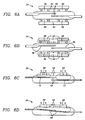
- Thermally operated reed switches which employ ferrite for switching at the Curie point are known in the art, see for example U.S. Patents No.'s 4,509,029; 4,703,296; and 4,434,411, which are hereby incorporated by reference, and several examples as depicted in Figures 6A to 6D.
- a ferrite material 44 having a chosen Curie temperature T c is placed in proximity to one or more permanent magnets 46.
- the magnets 46 and ferrite material 44 are positioned such that at a temperature below T c , when the ferrite material 44 is in a ferromagnetic state, the magnetic field and lines of flux of the permanent magnets 46 expand to include the ferrite material 44. Above T c the ferrite's magnetic reluctance is greatly increased and the ferrite material 44 loses its ability to conduct magnetic flux and hence becomes paramagnetic. At this point, the effective magnetic flux shrinks to the size generated by the permanent magnets 46 alone.
- the change in size of the magnetic field which occurs at the Curie temperature of the ferrite 44 is thus used to control a switching device, often by opening and closing the contacts of a reed switch 48 located in proximity to the magnets 46 and the ferrite material 44.
- the flux path includes the reed switch 48 which thus closes and forms a current path through the switch 34.
- the flux path does not include the reed switch 48, which thus opens, so that no current path exists through the switch 34.
- the opening and closing temperatures of the switch 34 are easily selectable by choosing a ferrite material 44 with the desired Curie temperature and by sizing and positioning the various components such as the magnets 46 and the switch conductors 48.
- Ferrite reed switches are thermally actuated, independent of power output and current flow, and produce negligible heat. Ferrite reed switches can be readily designed to switch at any desired temperature in a range from below about -20°C to above 130°C, and often to above 500°C.
- the described switch is only one embodiment of many combinations of magnetic phase changing materials and magnets which may be used to control a switch.
- the present invention is not limited to a single heating element between the switch 34 and the conductor 20. While often a single resistive heat producing element will be utilized, in some embodiments two or more resistive elements of either the same or different designs may be utilized in series with the ferrite switch 34. Such resistors could have a positive temperature coefficient of resistance (PTC), a zero temperature coefficient of resistance (ZTC), or a negative temperature coefficient of resistance (NTC). For example, it is commonly desirable to have a heating cable in which a PTC resistor and a ZTC resistor are aligned in series with each other and the ferrite switch 34 to form a single zone.
- PTC positive temperature coefficient of resistance
- ZTC zero temperature coefficient of resistance
- NTC negative temperature coefficient of resistance
- the resistive element could also be a PTC ceramic chip or a heating element made from a conductive polymer which could have either a positive, negative or zero temperature coefficient of resistance.
- the length and resistance of the heat producing element can be chosen to give whatever heat output is desirable for the zone when selected in combination with the power supply voltage.
- the self-regulating cable can be made up of as many individual zones of whatever length as is appropriate, but most commonly they will be between several inches to several feet in length.
- the zones are all connected in parallel to each other between the conductors to form an elongated heating cable of whatever length may be desired. Consequently, each zone generates the heat required for the particular zone which is controlled by a single low current controller.
- the insulation material 24 was a thermoplastic rubber.
- the ferrite switch lead 36 in contact with the conductor 22 was attached by soldering for good electrical contact.
- the notches 26, 28 and 30 were 12 inches on center.
- Electric insulation 65 for the switch leads 36 and 37 and conductor 22 was provided by high temperature TEFLON tape.
- a 40 gauge nichrome wire having a resistance of approximately 2.3 ohms/cm (70 ohms/foot) was wrapped at a rate of approximately 20 feet per lineal foot of cable to provide approximately 5 watts per when used with a 120 VAC power supply.
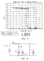
- the cable samples were then placed in an environmental chamber. Cable power output was measured and graphed against chamber temperature. The results are shown in Figure 7. All three cable samples exhibit square wave power curves, referring to the sharp drop in power output at the switching temperature.
- a second embodiment of a heating cable of the present invention employs a ferrite switch aligned in parallel with one or more heating elements. The parallel assembly is then connected in series with an additional heating element to form a heating zone.
- the cycling time or switching frequency of the ferrite switch 34 can be slowed by connecting a PTC element 50 in parallel with the ferrite switch 34, as shown in Fig. 8.
- a cable C2 in which the PTC element 50 has a switching temperature slightly below the Curie temperature of the ferrite switch 34, the result will be a power output which drops appreciably at the opening temperature of the ferrite switch 34. The power output will not, however, drop to zero.
- the power output is now controlled by the PTC element 50. It is desirable that the PTC element 50 switching temperature be below the ferrite switch 34 switching temperature so that when the ferrite switch 34 opens the PTC element 50 has a relatively high resistance. If the resistance of the PTC element 50 was too low, the cable C2 might continue heating up and cable power output would not be controlled at the ferrite switch 34 switching temperature.
- resistive element in parallel with the ferrite switch 34 has a zero temperature coefficient of resistance, such as resistive wire, this example being shown as an alternative in Figure 8, or a negative temperature coefficient of resistance provided that the resistances are such that the installed cable cools when the switch 34 is open.
- One preferred embodiment of the cable C2 is a cable C2A as shown in Fig. 9 where a ceramic chip is the PTC element 50.
- This embodiment utilizes a PTC ceramic chip 54 in parallel with a ferrite reed switch 34.
- a strip of insulation material 24 is extruded over two conductors 20 and 22.
- the insulation material 24 is notched at appropriate intervals 26, 28, 30 and 56.
- the notches 28 and 56 are located between the notches 26 and 30 and on the alternate conductor.
- the PTC ceramic chip 54 and the ferrite switch 34 are positioned in recesses 58 and 60 in the insulation material.
- One lead 36 of the ferrite switch 34 is connected to the first conductor 20, while a second switch lead 37 is connected to one surface of the ceramic chip 54.
- a third lead 66 is connected from the second side of the ceramic chip 54 to the first conductor 20. All of the exposed wires, including both sides of the ceramic chip 54, are electrically insulated, except that a small section of the lead 37 connecting the switch 34 and the chip 54 is left bare, as are the conductor 22 notched areas 26 and 30.
- the cable C2A is then spirally wound with resistive nichrome wire, for example, with a resistance of 70 2.3 ohms/cm (ohms/foot) at 20.5 feet per one foot zone, a zone here being the distance between the two notches 26 and 30. Again, the entire cable assembly is overjacketed with primary insulation 40. It will be understood that, as with the previous embodiments, it is possible to design a cable with components having any values which may be desired. The example uses one particular set of values for the components in the general cable design for the present embodiment.
- the exemplary resistive nichrome wire has a resistance of 1440 ohms/zone. With a power supply of 120 VAC this will result in a power output of 10 watts per zone when the ferrite switch 34 is in the closed position.
- the cable C2A includes a ferrite switch 34 having a Curie temperature of 74°C (165°F) and a PTC ceramic chip 54 having a Curie temperature of 155°F and a resistance of 500 ohms at 74°C (165°F).
- the ferrite switch 34 opens and in order to complete the circuit of the zone the current passes through the chip 54 giving a total circuit resistance of 1940 ohms.
- FIG. 10 An embodiment of the invention of a cable C2B using a parallel resistive wire is shown in Figure 10.
- two conductors 20 and 22 are held within a notched insulation material 24, having notches 26, 28 and 30 and the ferrite switches 34 are located in recesses 32 in the center of the insulation material 24.
- the ferrite switches 34 are arranged with all of their second leads 37 oriented in the same direction along the cable C2B and extending a uniform appropriate distance, such as half the total length of the zone.
- the zone in this case is the distance between the alternating notches in the cable C2B.
- the first lead 36 is connected to the conductor 20 or 22.
- the first lead 36 and an appropriate amount of the second lead 37 are then insulated, such as with high temperature TEFLON tape, except at the notches 26, 28 and 30 so that the conductor 20 or 22 and a portion of the second lead 37 remains exposed.
- the partially assembled cable C2B is then spirally wrapped with a resistive wire, for example 3.4 ohms/cm (105 ohms/foot) nichrome wire, so as to make electrical contact with all of the exposed conductors 20 and 22 and second leads 37.
- the entire cable C2B is then covered with a primary insulation layer 40, for example extruded polyethylene, as is well known to those skilled in the art.
- the ferrite switch 34 effectively shorts out or bypasses one-half of the resistive wire between alternating notches 26 and 28 or 28 and 30.
- the temperature of the ferrite switch 34 is above its Curie temperature, the current must pass through the entire length of the wire, thus having a reduced power output because of the increased resistance.
- the ferrite switch 34 is closed and a portion of the resistive wire is bypassed reducing the resistance between the conductors 20 and 22 for that zone, increasing the power supplied.
- a minimum amount of power is always being supplied, but greater power is supplied when the zone is below the Curie temperature of the switch 34.
- a 120 VAC power source is connected to the conductors 20 and 22.
- the individual zones, the distance between the notches 26, 28 and 30, are 1 foot long with the exposed or second lead 37 from the ferrite switch 34 extending six inches into the zone.
- Forty-two gauge, 3.4 ohms/cm (105 ohms/foot) nichrome wire is wound at a rate of 13.7 feet per 6 lineal inches of cable length resulting in a total resistance of approximately 1440 ohms per 15 cm (6 inches).
- the resistance of the ferrite switch 34 in the closed position is assumed to be substantially zero, the total resistance of a zone will be 1440 ohms with the ferrite switch 34 closed, the resistance of the wire from notch 26 to the second lead 37 of the switch 34 connected to the other conductor 22. This results in a power output of approximately 10 watts per zone.
- the switch 34 will open and current will flow through the second six inch portion of the nichrome wire wrapped cable C2B to reach the second conductor 22.
- the resistance of the second 15 cm (six inches), that portion which is in parallel to the ferrite switch 34, is also approximately 1440 ohms, the total resistance of the zone becomes approximately 2880 ohms and power output at 120 volts drops to approximately 5 watts per zone.
- the cable temperature will slowly fall until the cable temperature reaches the power on or Curie temperature of the ferrite switch 34, in this case 71°C (162°F). At this point the ferrite switch 34 closes and cable power again returns to 10 watts per zone.
- the cable C2B heats the pipe until the temperature of the switch 34 exceeds 71°C (162°F).
- the switch 34 opens, the resistance increases to 2880 ohms and the power drops to 5 watts per zone.
- the pipe begins cooling and the cycle is repeated. It will be recognized that in this embodiment the cable C2B at full power is effectively producing power only at 6 inch intervals or each foot of length.
Landscapes
- Resistance Heating (AREA)
- Manufacturing Of Electric Cables (AREA)
- Superconductors And Manufacturing Methods Therefor (AREA)
- Control Of Resistance Heating (AREA)
- Remote Monitoring And Control Of Power-Distribution Networks (AREA)
Claims (26)
- Elektrisches Heizkabel (C) mit einer Vielzahl von Heizzonen, mit:
ersten und zweiten elektrischen Leitermitteln (20, 22), die sich im wesentlichen parallel zueinander und voneinander beabstandet entlang der Länge des Kabels zum Tragen elektrischen Stromes erstrecken;
isolierenden Mitteln (24), die die elektrischen Leiter zur elektrischen Isolation der elektrischen Leiter voneinander einkapseln;
Heizmitteln (38) in jeder Zone, die mit dem ersten elektrischen Leiter verbunden sind zur Erzeugung von Wärme, wenn elektrischer Strom durch die Heizmittel fließt; und einem thermisch betätigten Schalter (34) in jeder Zone, der mit dem zweiten elektrischen Leiter (20) und mit den Heizmitteln (38) verbunden ist, wobei es der Schalter (34) zuläßt, daß Strom von dem ersten elektrischen Leiter (22) durch die Heizmittel (38) zu dem zweiten elektrischen Leiter (20) fließt, wenn die Temperatur des Schalters (34) unterhalb einer gegebenen Temperatur ist, und wobei er den durch die Heizmittel (38) fließenden Strom abschaltet, wenn die Temperatur des Schalters (34) oberhalb der gegebenen Temperatur ist, wobei der Schalter (34) eindeutig offen ist, wenn die Schaltertemperatur oberhalb der gegebenen Temperatur ist und eindeutig geschlossen ist, wenn die Schaltertemperatur unterhalb der gegebenen Temperatur ist. - Heizkabel nach Anspruch 1, bei dem das Heizmittel einen bezüglich der Temperatur im wesentlichen konstanten elektrischen Widerstand hat.
- Heizkabel nach Anspruch 1 oder 2, bei dem das Heizmittel Widerstandsmaterial aufweist, das spiralig um das Isolationsmittel und schalterisolierende Mittel herumgewunden ist und bei dem das Widerstandsmaterial den ersten elektrischen Leiter an der ersten Leiterkerbe kontaktiert und den zweiten Schalterleiter kontaktiert.
- Heizkabel nach Anspruch 3, bei dem das Widerstandsmaterial aus Widerstandsfolie gebildet ist.
- Heizkabel nach einem der vorhergehenden Ansprüche, bei dem das Heizmittel ein nicht-metallisches, elektrisch leitendes Material aufweist.
- Heizkabel nach einem der vorhergehenden Ansprüche, bei dem der Schalter magnetisch gesteuert wird.
- Elektrisches Heizkabel (C) mit einer Vielzahl von Heizzonen, mit:
ersten und zweiten elektrischen Leitermitteln (20, 22), die sich im wesentlichen parallel zueinander und voneinander beabstandet entlang der Länge des Kabels zum Tragen elektrischen Stromes erstrecken;
isolierenden Mitteln (24), die die elektrischen Leiter (20,22) zur elektrischen Isolation der elektrischen Leiter voneinander einkapseln;
Heizmittel (38) in jeder Zone, die mit dem ersten elektrischen Leiter (22) verbunden sind, zur Erzeugung von Wärme, wenn elektrischer Strom durch die ersten Heizmittel fließt;
einem thermisch betätigten Schalter (34) in jeder Zone, der mit dem zweiten elektrischen Leiter (20) und mit dem ersten Heizmittel (38) verbunden ist, wobei der Schalter eindeutig offen ist, wenn die Schaltertemperatur oberhalb einer gegebenen Temperatur ist und eindeutig geschlossen ist, wenn die Schaltertemperatur unterhalb der gegebenen Temperatur ist; und
ein Widerstands-Heizelement (50) in jeder Zone, das parallel zu dem Schalter (34) verbunden ist, so daß Strom durch das Widerstandselement fließt, wenn der Schalter offen ist, und daß Strom im wesentlichen am Widerstandselement vorbei durch den Schalter abgezweigt wird, wenn der Schalter geschlossen ist. - Heizkabel nach einem der vorhergehenden Ansprüche, bei dem das Isolationsmittel in jeder Zone mindestens eine Kerbe aufweist, die den zweiten elektrischen Leiter freilegt, und wobei der Schalter mit dem elektrischen Leiter an der Kerbe verbunden ist.
- Heizkabel nach einem der vorhergehenden Ansprüche, bei dem das Isoliermittel in jeder Zone eine Kerbe aufweist, die den ersten elektrischen Leiter freilegt, und bei dem das Heizmittel mit dem ersten elektrischen Leiter an der Kerbe verbunden ist.
- Heizkabel nach einem der vorhergehenden Ansprüche, bei dem das Isoliermittel in jeder Zone eine Ausnehmung in dem Abschnitt zwischen dem ersten und dem zweiten Leiter aufweist und bei dem der Schalter teilweise in der Ausnehmung angeordnet ist.
- Heizkabel nach einem der vorhergehenden Ansprüche, bei dem der Schalter einen Körper und erste und zweite Leiter aufweist, wobei der erste Leiter mit dem zweiten elektrischen Leiter und der zweite Leiter mit dem Heizmittel verbunden ist, wobei das Heizkabel weiterhin Schalter-Isolationsmittel aufweist, die die zweite Leiterkerbe, den Schalterkörper, den ersten Schalterleiter und einen Abschnitt des zweiten Schalterleiters abdecken.
- Heizkabel nach einem der vorhergehenden Ansprüche, bei dem das Isolationsmittel in jeder Zone eine Kerbe aufweist, die dem Widerstandsheizelement zugeordnet ist und die den zweiten elektrischen Leiter freilegt, wobei das Widerstandsheizelement einen Körper und einen ersten Leiter aufweist, wobei der erste Leiter mit dem zweiten elektrischen Leiter an der zugeordneten Kerbe verbunden ist und wobei der zweite Leiter des Schalters mit dem Körper des Widerstandsheizelementes verbunden ist, und wobei das Heizkabel weiterhin Widerstandsheizelement-Isolationsmittel aufweist, die die dem zweiten Leiter-Widerstandselement zugeordnete Kerbe, den Körper des Widerstandsheizelementes und den ersten Leiter des Widerstandsheizelementes abdecken.
- Heizkabel nach einem der vorhergehenden Ansprüche, bei dem das Heizmittel Widerstandsmaterial aufweist, das spiralig um das Isolationsmittel herumgewunden ist, und bei dem das Widerstandsmaterial den ersten elektrischen Leiter an der ersten Leiterkerbe kontaktiert, und den zweiten Schalterleiter kontaktiert.
- Heizkabel nach einem der vorhergehenden Ansprüche, bei dem das Widerstandsmaterial Widerstandsheizdraht aufweist.
- Heizkabel nach einem der vorhergehenden Ansprüche, bei dem der Heizdraht im wesentlichen aus Nickelchrom (nichrome) besteht.
- Heizkabel nach einem der vorhergehenden Ansprüche, bei dem der Schalter einen Abschnitt aufweist, der bei der gegebenen Temperatur von einer ferromagnetischen Phase zu einer paramagnetischen Phase umwandelt.
- Heizkabel nach einem der vorhergehenden Ansprüche, bei dem der magnetisch umwandelnde Abschnitt des Schalters im wesentlichen aus Ferrit besteht.
- Heizkabel nach einem der vorhergehenden Ansprüche, bei dem der Schalter weiterhin einen Reed-Schalter (reed switch) aufweist.
- Heizkabel nach einem der vorhergehenden Ansprüche, bei dem das Widerstandsheizelement aus elektrischem Widerstandsdraht besteht.
- Heizkabel nach Anspruch 18, bei dem das Widerstandsheizelement einen positiven Temperaturkoeffizienten des Widerstandes hat.
- Heizkabel nach Anspruch 18 und 20, bei dem der Curie-Punkt des Widerstandsheizelementes niedriger liegt als der Curie-Punkt des Schalters.
- Heizkabel nach einem der vorhergehenden Ansprüche, bei dem das Widerstandsheizelement einen keramischen Chip aufweist.
- Verfahren zum Aufbau eines zonenartigen elektrischen Heizkabels (C) mit:
Extrusion eines isolierenden Materials (24) über erste und zweite parallele elektrische Leiter (20, 22), während die Leiter voneinander beabstandet sind;
Einkerbung des isolierenden Materials so, daß die ersten und zweiten elektrischen Leiter in Abständen freigelegt werden;
Bildung von Ausnehmungen (28) in dem isolierenden Material zwischen den elektrischen Leitern;
Anordnen eines thermisch empfindlichen Schalters (34) mit eindeutiger Aktion (Betätigung), der einen ersten Leiter und einen zweiten Leiter hat, in jede der Ausnehmungen (28) des isolierenden Materials;
Verbindung des ersten Leiters des Schalters mit dem ersten elektrischen Leiter (20) an einer der Kerben; spiraliger Windung eines Widerstandsmaterials (38) um das isolierende Material;
Verbindung des zweiten Leiters des Schalters mit dem Heizdraht (38);
Verbindung des Heizdrahtes (38) mit dem zweiten elektrischen Leiter (22), so daß jeder der Schalter elektrisch in Reihe angeordnet ist mit einem Abschnitt des Heizdrahtes zwischen den ersten und den zweiten Leitern, und Umgeben des Heizdrahtes (38), der Leiter (20, 22), der Schalter (34) und des isolierenden Materials (24) mit einer schützenden Umhüllung (40). - Verfahren nach Anspruch 23, weiterhin mit:
Bereitstellung eines Widerstandselementes;
Verbindung des Widerstandsheizelementes mit der elektrischen Verbindungsstelle des zweiten Leiters des Schalters und des Heizdrahtes und mit dem ersten elektrischen Leiter so, daß das Widerstandsheizelement und der Schalter zwischen dem ersten Leiter und dem Heizdraht elektrisch parallel ausgerichtet sind. - Verfahren nach Anspruch 23 oder 24, bei dem das Widerstandsheizelement ein keramischer Chip mit positiven Temperaturkoeffizienten des Widerstandes ist.
- Verfahren nach Anspruch 23 oder 24, bei dem das Widerstandsheizelement ein Heizdraht ist.
Applications Claiming Priority (2)
| Application Number | Priority Date | Filing Date | Title |
|---|---|---|---|
| US58644190A | 1990-09-20 | 1990-09-20 | |
| US586441 | 1990-09-20 |
Publications (2)
| Publication Number | Publication Date |
|---|---|
| EP0476637A1 EP0476637A1 (de) | 1992-03-25 |
| EP0476637B1 true EP0476637B1 (de) | 1995-01-25 |
Family
ID=24345737
Family Applications (1)
| Application Number | Title | Priority Date | Filing Date |
|---|---|---|---|
| EP91115902A Expired - Lifetime EP0476637B1 (de) | 1990-09-20 | 1991-09-19 | Schalter-gesteuertes zonenartiges Heizkabel und Verfahren |
Country Status (9)
| Country | Link |
|---|---|
| US (1) | US5512732A (de) |
| EP (1) | EP0476637B1 (de) |
| JP (1) | JPH04272680A (de) |
| KR (1) | KR920007492A (de) |
| AT (1) | ATE117863T1 (de) |
| AU (1) | AU646498B2 (de) |
| CA (1) | CA2051334C (de) |
| DE (1) | DE69106989T2 (de) |
| MX (1) | MX9101178A (de) |
Cited By (1)
| Publication number | Priority date | Publication date | Assignee | Title |
|---|---|---|---|---|
| EP4687371A1 (de) * | 2024-08-01 | 2026-02-04 | nVent Services GmbH | Keramisches selbstregulierendes heizkabel mit positivem temperaturkoeffizienten |
Families Citing this family (91)
| Publication number | Priority date | Publication date | Assignee | Title |
|---|---|---|---|---|
| US6410893B1 (en) * | 1998-07-15 | 2002-06-25 | Thermon Manufacturing Company | Thermally-conductive, electrically non-conductive heat transfer material and articles made thereof |
| EA200201127A1 (ru) | 2000-04-24 | 2003-06-26 | Шелл Интернэшнл Рисерч Маатсхаппий Б.В. | Извлечение углеводородов на месте залегания из керогенсодержащей формации |
| DE60125682T2 (de) * | 2000-10-19 | 2007-11-15 | Heat Trace Ltd. | Heizkabel |
| US6877555B2 (en) | 2001-04-24 | 2005-04-12 | Shell Oil Company | In situ thermal processing of an oil shale formation while inhibiting coking |
| CN100540843C (zh) | 2001-10-24 | 2009-09-16 | 国际壳牌研究有限公司 | 利用自然分布型燃烧器对含烃岩层进行就地热处理的方法 |
| GB0216932D0 (en) * | 2002-07-20 | 2002-08-28 | Heat Trace Ltd | Electrical heating cable |
| US7121341B2 (en) | 2002-10-24 | 2006-10-17 | Shell Oil Company | Conductor-in-conduit temperature limited heaters |
| DE10301780B3 (de) * | 2003-01-18 | 2004-08-26 | Dräger Medical AG & Co. KGaA | Verfahren zur Regelung der Temperatur einer Inkubatorhaube |
| CA2524689C (en) | 2003-04-24 | 2012-05-22 | Shell Canada Limited | Thermal processes for subsurface formations |
| CA2563583C (en) | 2004-04-23 | 2013-06-18 | Shell Internationale Research Maatschappij B.V. | Temperature limited heaters used to heat subsurface formations |
| US8070840B2 (en) | 2005-04-22 | 2011-12-06 | Shell Oil Company | Treatment of gas from an in situ conversion process |
| US7220947B2 (en) * | 2005-09-30 | 2007-05-22 | Global Heating Solutions, Inc. | Pipe heater |
| KR101434259B1 (ko) | 2005-10-24 | 2014-08-27 | 쉘 인터내셔날 리써취 마트샤피지 비.브이. | 탄화수소 함유 지층을 처리하기 위한 병합 발생 시스템 및방법 |
| EP2010754A4 (de) | 2006-04-21 | 2016-02-24 | Shell Int Research | Einstellende legierungszusammensetzungen für ausgewählte eigenschaften in temperaturbegrenzten heizern |
| CA2665865C (en) | 2006-10-20 | 2015-06-16 | Shell Internationale Research Maatschappij B.V. | Heating hydrocarbon containing formations in a spiral startup staged sequence |
| WO2008055307A1 (en) * | 2006-11-08 | 2008-05-15 | Resmed Ltd | Humidifier for respiratory apparatus |
| EP3782688B8 (de) | 2006-11-08 | 2022-11-02 | ResMed Pty Ltd | Beatmungsgerät |
| CN101680287B (zh) | 2007-04-20 | 2013-12-18 | 国际壳牌研究有限公司 | 用于地下地层的加热系统和用于加热地下地层的方法 |
| JP5379804B2 (ja) | 2007-10-19 | 2013-12-25 | シエル・インターナシヨネイル・リサーチ・マーチヤツピイ・ベー・ウイ | 炭化水素含有層の処理用熱源の不規則な間隔 |
| US8779879B2 (en) | 2008-04-04 | 2014-07-15 | Correlated Magnetics Research LLC | System and method for positioning a multi-pole magnetic structure |
| US8760251B2 (en) | 2010-09-27 | 2014-06-24 | Correlated Magnetics Research, Llc | System and method for producing stacked field emission structures |
| CA2723437A1 (en) | 2008-04-04 | 2009-10-08 | Cedar Ridge Research, Llc | Techniques for producing an electrical pulse |
| US7800471B2 (en) | 2008-04-04 | 2010-09-21 | Cedar Ridge Research, Llc | Field emission system and method |
| US8279032B1 (en) | 2011-03-24 | 2012-10-02 | Correlated Magnetics Research, Llc. | System for detachment of correlated magnetic structures |
| US8760250B2 (en) | 2009-06-02 | 2014-06-24 | Correlated Magnetics Rsearch, LLC. | System and method for energy generation |
| US9202615B2 (en) | 2012-02-28 | 2015-12-01 | Correlated Magnetics Research, Llc | System for detaching a magnetic structure from a ferromagnetic material |
| US7843295B2 (en) | 2008-04-04 | 2010-11-30 | Cedar Ridge Research Llc | Magnetically attachable and detachable panel system |
| US8717131B2 (en) | 2008-04-04 | 2014-05-06 | Correlated Magnetics Research | Panel system for covering a glass or plastic surface |
| US8576036B2 (en) | 2010-12-10 | 2013-11-05 | Correlated Magnetics Research, Llc | System and method for affecting flux of multi-pole magnetic structures |
| US8179219B2 (en) | 2008-04-04 | 2012-05-15 | Correlated Magnetics Research, Llc | Field emission system and method |
| US9371923B2 (en) | 2008-04-04 | 2016-06-21 | Correlated Magnetics Research, Llc | Magnetic valve assembly |
| US9202616B2 (en) | 2009-06-02 | 2015-12-01 | Correlated Magnetics Research, Llc | Intelligent magnetic system |
| US9105380B2 (en) | 2008-04-04 | 2015-08-11 | Correlated Magnetics Research, Llc. | Magnetic attachment system |
| US8115581B2 (en) | 2008-04-04 | 2012-02-14 | Correlated Magnetics Research, Llc | Techniques for producing an electrical pulse |
| US8648681B2 (en) | 2009-06-02 | 2014-02-11 | Correlated Magnetics Research, Llc. | Magnetic structure production |
| US8174347B2 (en) | 2010-07-12 | 2012-05-08 | Correlated Magnetics Research, Llc | Multilevel correlated magnetic system and method for using the same |
| US8816805B2 (en) | 2008-04-04 | 2014-08-26 | Correlated Magnetics Research, Llc. | Magnetic structure production |
| US8368495B2 (en) | 2008-04-04 | 2013-02-05 | Correlated Magnetics Research LLC | System and method for defining magnetic structures |
| US7868721B2 (en) * | 2008-04-04 | 2011-01-11 | Cedar Ridge Research, Llc | Field emission system and method |
| EP2262978A1 (de) | 2008-04-18 | 2010-12-22 | Shell Internationale Research Maatschappij B.V. | Verwendung von minen und tunneln zur behandlung unterirdischer kohlenwasserstoffhaltiger formierungen |
| US7958575B2 (en) * | 2008-05-20 | 2011-06-14 | Cedar Ridge Research, Llc | Toilet safety apparatus, systems, and methods |
| US8015752B2 (en) | 2008-05-20 | 2011-09-13 | Correlated Magnetics Research, Llc | Child safety gate apparatus, systems, and methods |
| US8016330B2 (en) * | 2008-05-20 | 2011-09-13 | Correalated Magnetics Research, LLC | Appliance safety apparatus, systems, and methods |
| AU2009303608B2 (en) | 2008-10-13 | 2013-11-14 | Shell Internationale Research Maatschappij B.V. | Using self-regulating nuclear reactors in treating a subsurface formation |
| US8917154B2 (en) | 2012-12-10 | 2014-12-23 | Correlated Magnetics Research, Llc. | System for concentrating magnetic flux |
| US8937521B2 (en) | 2012-12-10 | 2015-01-20 | Correlated Magnetics Research, Llc. | System for concentrating magnetic flux of a multi-pole magnetic structure |
| US8448707B2 (en) | 2009-04-10 | 2013-05-28 | Shell Oil Company | Non-conducting heater casings |
| US9404776B2 (en) | 2009-06-02 | 2016-08-02 | Correlated Magnetics Research, Llc. | System and method for tailoring polarity transitions of magnetic structures |
| US9257219B2 (en) | 2012-08-06 | 2016-02-09 | Correlated Magnetics Research, Llc. | System and method for magnetization |
| US8704626B2 (en) | 2010-05-10 | 2014-04-22 | Correlated Magnetics Research, Llc | System and method for moving an object |
| US9275783B2 (en) | 2012-10-15 | 2016-03-01 | Correlated Magnetics Research, Llc. | System and method for demagnetization of a magnetic structure region |
| US9711268B2 (en) | 2009-09-22 | 2017-07-18 | Correlated Magnetics Research, Llc | System and method for tailoring magnetic forces |
| JP6001450B2 (ja) | 2009-09-22 | 2016-10-05 | コルレイティド マグネティクス リサーチ,リミティド ライアビリティ カンパニー | 多重レベル相関磁気システム及びその使用法 |
| US8816203B2 (en) | 2009-10-09 | 2014-08-26 | Shell Oil Company | Compacted coupling joint for coupling insulated conductors |
| US8356935B2 (en) * | 2009-10-09 | 2013-01-22 | Shell Oil Company | Methods for assessing a temperature in a subsurface formation |
| US9466896B2 (en) | 2009-10-09 | 2016-10-11 | Shell Oil Company | Parallelogram coupling joint for coupling insulated conductors |
| KR100985974B1 (ko) * | 2010-02-17 | 2010-10-06 | 서홍석 | 자전거용 작업대 |
| US8701769B2 (en) | 2010-04-09 | 2014-04-22 | Shell Oil Company | Methods for treating hydrocarbon formations based on geology |
| US8631866B2 (en) | 2010-04-09 | 2014-01-21 | Shell Oil Company | Leak detection in circulated fluid systems for heating subsurface formations |
| US8820406B2 (en) | 2010-04-09 | 2014-09-02 | Shell Oil Company | Electrodes for electrical current flow heating of subsurface formations with conductive material in wellbore |
| US9127523B2 (en) | 2010-04-09 | 2015-09-08 | Shell Oil Company | Barrier methods for use in subsurface hydrocarbon formations |
| US8502120B2 (en) | 2010-04-09 | 2013-08-06 | Shell Oil Company | Insulating blocks and methods for installation in insulated conductor heaters |
| US8939207B2 (en) | 2010-04-09 | 2015-01-27 | Shell Oil Company | Insulated conductor heaters with semiconductor layers |
| US8638016B2 (en) | 2010-09-17 | 2014-01-28 | Correlated Magnetics Research, Llc | Electromagnetic structure having a core element that extends magnetic coupling around opposing surfaces of a circular magnetic structure |
| US8857051B2 (en) | 2010-10-08 | 2014-10-14 | Shell Oil Company | System and method for coupling lead-in conductor to insulated conductor |
| US8586867B2 (en) | 2010-10-08 | 2013-11-19 | Shell Oil Company | End termination for three-phase insulated conductors |
| US8943686B2 (en) | 2010-10-08 | 2015-02-03 | Shell Oil Company | Compaction of electrical insulation for joining insulated conductors |
| US8279031B2 (en) | 2011-01-20 | 2012-10-02 | Correlated Magnetics Research, Llc | Multi-level magnetic system for isolation of vibration |
| US8702437B2 (en) | 2011-03-24 | 2014-04-22 | Correlated Magnetics Research, Llc | Electrical adapter system |
| US9016370B2 (en) | 2011-04-08 | 2015-04-28 | Shell Oil Company | Partial solution mining of hydrocarbon containing layers prior to in situ heat treatment |
| RU2587459C2 (ru) | 2011-04-08 | 2016-06-20 | Шелл Интернэшнл Рисерч Маатсхаппий Б.В. | Системы для соединения изолированных проводников |
| US9330825B2 (en) | 2011-04-12 | 2016-05-03 | Mohammad Sarai | Magnetic configurations |
| CA3177636A1 (en) | 2011-06-03 | 2012-12-06 | Fisher & Paykel Healthcare Limited | Medical tubes and methods of manufacture |
| US8963380B2 (en) | 2011-07-11 | 2015-02-24 | Correlated Magnetics Research LLC. | System and method for power generation system |
| US9219403B2 (en) | 2011-09-06 | 2015-12-22 | Correlated Magnetics Research, Llc | Magnetic shear force transfer device |
| US8848973B2 (en) | 2011-09-22 | 2014-09-30 | Correlated Magnetics Research LLC | System and method for authenticating an optical pattern |
| CN104011327B (zh) | 2011-10-07 | 2016-12-14 | 国际壳牌研究有限公司 | 利用地下地层中的绝缘导线的介电性能来确定绝缘导线的性能 |
| JO3141B1 (ar) | 2011-10-07 | 2017-09-20 | Shell Int Research | الوصلات المتكاملة للموصلات المعزولة |
| JO3139B1 (ar) | 2011-10-07 | 2017-09-20 | Shell Int Research | تشكيل موصلات معزولة باستخدام خطوة اختزال أخيرة بعد المعالجة الحرارية. |
| CA2850741A1 (en) | 2011-10-07 | 2013-04-11 | Manuel Alberto GONZALEZ | Thermal expansion accommodation for circulated fluid systems used to heat subsurface formations |
| US9605524B2 (en) | 2012-01-23 | 2017-03-28 | Genie Ip B.V. | Heater pattern for in situ thermal processing of a subsurface hydrocarbon containing formation |
| WO2013112133A1 (en) | 2012-01-23 | 2013-08-01 | Genie Ip B.V. | Heater pattern for in situ thermal processing of a subsurface hydrocarbon containing formation |
| US9245677B2 (en) | 2012-08-06 | 2016-01-26 | Correlated Magnetics Research, Llc. | System for concentrating and controlling magnetic flux of a multi-pole magnetic structure |
| CN104955510B (zh) | 2012-11-14 | 2017-05-10 | 费雪派克医疗保健有限公司 | 用于呼吸回路的分区加热 |
| JP6412879B2 (ja) | 2012-12-04 | 2018-10-24 | フィッシャー アンド ペイケル ヘルスケア リミテッド | 医療用チューブおよびその製造方法 |
| US9298281B2 (en) | 2012-12-27 | 2016-03-29 | Correlated Magnetics Research, Llc. | Magnetic vector sensor positioning and communications system |
| US10814091B2 (en) | 2013-10-24 | 2020-10-27 | Fisher & Paykel Healthcare Limited | System for delivery of respiratory gases |
| CN111265754B (zh) | 2014-03-17 | 2023-06-06 | 费雪派克医疗保健有限公司 | 用于呼吸系统的医用管 |
| JP7014717B2 (ja) | 2015-09-09 | 2022-02-01 | フィッシャー アンド ペイケル ヘルスケア リミテッド | 呼吸回路用の区域加熱 |
| US10278265B2 (en) * | 2016-08-29 | 2019-04-30 | Chromalox, Inc. | Heat trace signal light |
| KR102608504B1 (ko) | 2023-09-21 | 2023-12-01 | 김철재 | 이륜차량용 리프트장치 |
Family Cites Families (27)
| Publication number | Priority date | Publication date | Assignee | Title |
|---|---|---|---|---|
| US2719907A (en) * | 1952-04-19 | 1955-10-04 | Connecticut Hard Rubber Co | Heating tape and method of making same |
| US3757086A (en) * | 1972-10-05 | 1973-09-04 | W Indoe | Electrical heating cable |
| US3858144A (en) * | 1972-12-29 | 1974-12-31 | Raychem Corp | Voltage stress-resistant conductive articles |
| US4037083A (en) * | 1976-05-05 | 1977-07-19 | Leavines Joseph E | High temperature parallel resistance pipe heater |
| US4117312A (en) * | 1976-07-22 | 1978-09-26 | Thermon Manufacturing Company | Self-limiting temperature electrical heating cable |
| US4150400A (en) * | 1977-03-31 | 1979-04-17 | International Business Machines Corporation | Methods of a coarse-scan/fine-print character reproduction with compression |
| US4100673A (en) * | 1977-05-05 | 1978-07-18 | Leavines Joseph E | Method of making high temperature parallel resistance pipe heater |
| JPS5852593Y2 (ja) * | 1977-11-07 | 1983-11-30 | ティーディーケイ株式会社 | 感温リ−ドスイツチ |
| JPS5941256B2 (ja) * | 1979-05-14 | 1984-10-05 | 東北金属工業株式会社 | 帯域動作型サ−マルリ−ドスイッチ |
| US4250400A (en) * | 1979-11-19 | 1981-02-10 | The Scott & Fetzer Company | Flexible temperature self regulating heating cable |
| US4304044A (en) * | 1979-11-19 | 1981-12-08 | The Scott & Fetzer Company | Method for forming self-regulating heat trace cable |
| US4389628A (en) * | 1980-06-02 | 1983-06-21 | Tohoku Metal Industries, Ltd. | Thermo-magnetically operated switches having two different operating temperatures |
| JPS5744929A (en) * | 1980-08-29 | 1982-03-13 | Aisin Seiki | Temperature switch |
| US4362917A (en) * | 1980-12-29 | 1982-12-07 | Raytheon Company | Ferrite heating apparatus |
| US4414519A (en) * | 1982-03-10 | 1983-11-08 | Allied Corporation | Temperature-sensitive relay |
| US4434411A (en) * | 1982-03-10 | 1984-02-28 | Allied Corporation | Temperature-sensitive switch |
| US4454491A (en) * | 1982-05-10 | 1984-06-12 | Allied Corporation | Temperature sensing circuit breaker or switch |
| US4459473A (en) * | 1982-05-21 | 1984-07-10 | Raychem Corporation | Self-regulating heaters |
| US4695713A (en) * | 1982-09-30 | 1987-09-22 | Metcal, Inc. | Autoregulating, electrically shielded heater |
| JPS59212925A (ja) * | 1983-05-18 | 1984-12-01 | Matsushita Electric Ind Co Ltd | 加熱装置 |
| US4509029A (en) * | 1984-03-09 | 1985-04-02 | Midwest Components, Inc. | Thermally actuated switch |
| JPH0312188Y2 (de) * | 1985-02-07 | 1991-03-22 | ||
| US4794229A (en) * | 1987-04-24 | 1988-12-27 | Thermon Manufacturing Company | Flexible, elongated thermistor heating cable |
| US4733059A (en) * | 1987-06-15 | 1988-03-22 | Thermon Manufacturing Company | Elongated parallel, constant wattage heating cable |
| GB2209650B (en) * | 1987-09-05 | 1991-07-03 | Frederick William Bloore | Heating tape |
| US4922083A (en) * | 1988-04-22 | 1990-05-01 | Thermon Manufacturing Company | Flexible, elongated positive temperature coefficient heating assembly and method |
| CA1338315C (en) * | 1989-09-22 | 1996-05-07 | Glenwood Franklin Heizer | Cut to length heater cable |
-
1991
- 1991-09-12 JP JP3260421A patent/JPH04272680A/ja active Pending
- 1991-09-13 CA CA002051334A patent/CA2051334C/en not_active Expired - Fee Related
- 1991-09-19 DE DE69106989T patent/DE69106989T2/de not_active Expired - Fee Related
- 1991-09-19 KR KR1019910016356A patent/KR920007492A/ko not_active Withdrawn
- 1991-09-19 EP EP91115902A patent/EP0476637B1/de not_active Expired - Lifetime
- 1991-09-19 AU AU84618/91A patent/AU646498B2/en not_active Ceased
- 1991-09-19 MX MX9101178A patent/MX9101178A/es not_active IP Right Cessation
- 1991-09-19 AT AT91115902T patent/ATE117863T1/de not_active IP Right Cessation
-
1993
- 1993-01-07 US US08/001,894 patent/US5512732A/en not_active Expired - Lifetime
Cited By (1)
| Publication number | Priority date | Publication date | Assignee | Title |
|---|---|---|---|---|
| EP4687371A1 (de) * | 2024-08-01 | 2026-02-04 | nVent Services GmbH | Keramisches selbstregulierendes heizkabel mit positivem temperaturkoeffizienten |
Also Published As
| Publication number | Publication date |
|---|---|
| JPH04272680A (ja) | 1992-09-29 |
| AU8461891A (en) | 1992-03-26 |
| ATE117863T1 (de) | 1995-02-15 |
| DE69106989T2 (de) | 1995-09-07 |
| KR920007492A (ko) | 1992-04-28 |
| US5512732A (en) | 1996-04-30 |
| MX9101178A (es) | 1992-05-04 |
| EP0476637A1 (de) | 1992-03-25 |
| CA2051334C (en) | 1997-06-24 |
| AU646498B2 (en) | 1994-02-24 |
| DE69106989D1 (de) | 1995-03-09 |
| CA2051334A1 (en) | 1992-03-21 |
Similar Documents
| Publication | Publication Date | Title |
|---|---|---|
| EP0476637B1 (de) | Schalter-gesteuertes zonenartiges Heizkabel und Verfahren | |
| KR100786679B1 (ko) | 전기 가열장치 및 리셋가능 퓨즈 | |
| US4352083A (en) | Circuit protection devices | |
| EP0417097B1 (de) | Heizelement und verfahren zur herstellung eines heizelementes | |
| US4577094A (en) | Electrical heating apparatus protected against an overheating condition | |
| US4072848A (en) | Electrical heating cable with temperature self-limiting heating elements | |
| US4317027A (en) | Circuit protection devices | |
| US4017715A (en) | Temperature overshoot heater | |
| CA1228653A (en) | Electrical heating apparatus protected against an overheating condition and a temperature sensitive electrical sensor for use therewith | |
| US2782290A (en) | Temperature responsive control device | |
| EP2324682B1 (de) | Heizkabel | |
| US7566849B2 (en) | Self-regulating electrical heating cable | |
| JPH0461578B2 (de) | ||
| US4684785A (en) | Electric blankets | |
| EP1829425B1 (de) | Steuerung eines heizungskabels | |
| US4565455A (en) | Heat regulating sensor tape | |
| EP1537761B1 (de) | Elektrisches heizkabel | |
| US6002117A (en) | Electric heating cord with non-heating core-conducting element and reduced EMF emissions | |
| CA1244863A (en) | Electric blanket or pad having improved positive temperature coefficient heater circuit | |
| US5432323A (en) | Regulated electric strip heater |
Legal Events
| Date | Code | Title | Description |
|---|---|---|---|
| PUAI | Public reference made under article 153(3) epc to a published international application that has entered the european phase |
Free format text: ORIGINAL CODE: 0009012 |
|
| AK | Designated contracting states |
Kind code of ref document: A1 Designated state(s): AT BE CH DE DK ES FR GB GR IT LI LU NL SE |
|
| 17P | Request for examination filed |
Effective date: 19920917 |
|
| 17Q | First examination report despatched |
Effective date: 19940217 |
|
| GRAA | (expected) grant |
Free format text: ORIGINAL CODE: 0009210 |
|
| AK | Designated contracting states |
Kind code of ref document: B1 Designated state(s): AT BE CH DE DK ES FR GB GR IT LI LU NL SE |
|
| PG25 | Lapsed in a contracting state [announced via postgrant information from national office to epo] |
Ref country code: CH Effective date: 19950125 Ref country code: GR Free format text: LAPSE BECAUSE OF FAILURE TO SUBMIT A TRANSLATION OF THE DESCRIPTION OR TO PAY THE FEE WITHIN THE PRESCRIBED TIME-LIMIT Effective date: 19950125 Ref country code: ES Free format text: THE PATENT HAS BEEN ANNULLED BY A DECISION OF A NATIONAL AUTHORITY Effective date: 19950125 Ref country code: DK Effective date: 19950125 Ref country code: IT Free format text: LAPSE BECAUSE OF FAILURE TO SUBMIT A TRANSLATION OF THE DESCRIPTION OR TO PAY THE FEE WITHIN THE PRE;WARNING: LAPSES OF ITALIAN PATENTS WITH EFFECTIVE DATE BEFORE 2007 MAY HAVE OCCURRED AT ANY TIME BEFORE 2007. THE CORRECT EFFECTIVE DATE MAY BE DIFFERENT FROM THE ONE RECORDED.SCRIBED TIME-LIMIT Effective date: 19950125 Ref country code: LI Effective date: 19950125 Ref country code: BE Effective date: 19950125 Ref country code: AT Effective date: 19950125 |
|
| REF | Corresponds to: |
Ref document number: 117863 Country of ref document: AT Date of ref document: 19950215 Kind code of ref document: T |
|
| REF | Corresponds to: |
Ref document number: 69106989 Country of ref document: DE Date of ref document: 19950309 |
|
| PG25 | Lapsed in a contracting state [announced via postgrant information from national office to epo] |
Ref country code: SE Effective date: 19950425 |
|
| REG | Reference to a national code |
Ref country code: CH Ref legal event code: PL |
|
| ET | Fr: translation filed | ||
| PG25 | Lapsed in a contracting state [announced via postgrant information from national office to epo] |
Ref country code: LU Free format text: LAPSE BECAUSE OF NON-PAYMENT OF DUE FEES Effective date: 19950930 |
|
| PLBE | No opposition filed within time limit |
Free format text: ORIGINAL CODE: 0009261 |
|
| STAA | Information on the status of an ep patent application or granted ep patent |
Free format text: STATUS: NO OPPOSITION FILED WITHIN TIME LIMIT |
|
| 26N | No opposition filed | ||
| PGFP | Annual fee paid to national office [announced via postgrant information from national office to epo] |
Ref country code: GB Payment date: 20000913 Year of fee payment: 10 |
|
| PGFP | Annual fee paid to national office [announced via postgrant information from national office to epo] |
Ref country code: DE Payment date: 20000918 Year of fee payment: 10 |
|
| PGFP | Annual fee paid to national office [announced via postgrant information from national office to epo] |
Ref country code: FR Payment date: 20000926 Year of fee payment: 10 |
|
| PGFP | Annual fee paid to national office [announced via postgrant information from national office to epo] |
Ref country code: NL Payment date: 20000928 Year of fee payment: 10 |
|
| PG25 | Lapsed in a contracting state [announced via postgrant information from national office to epo] |
Ref country code: GB Free format text: LAPSE BECAUSE OF NON-PAYMENT OF DUE FEES Effective date: 20010919 |
|
| REG | Reference to a national code |
Ref country code: GB Ref legal event code: IF02 |
|
| PG25 | Lapsed in a contracting state [announced via postgrant information from national office to epo] |
Ref country code: NL Free format text: LAPSE BECAUSE OF NON-PAYMENT OF DUE FEES Effective date: 20020401 |
|
| PG25 | Lapsed in a contracting state [announced via postgrant information from national office to epo] |
Ref country code: DE Free format text: LAPSE BECAUSE OF NON-PAYMENT OF DUE FEES Effective date: 20020501 |
|
| GBPC | Gb: european patent ceased through non-payment of renewal fee |
Effective date: 20010919 |
|
| PG25 | Lapsed in a contracting state [announced via postgrant information from national office to epo] |
Ref country code: FR Free format text: LAPSE BECAUSE OF NON-PAYMENT OF DUE FEES Effective date: 20020531 |
|
| NLV4 | Nl: lapsed or anulled due to non-payment of the annual fee |
Effective date: 20020401 |
|
| REG | Reference to a national code |
Ref country code: FR Ref legal event code: ST |
|
| NLV4 | Nl: lapsed or anulled due to non-payment of the annual fee |
Effective date: 20020401 |