EP0476807A1 - Cathéters orientables à noyau en fil - Google Patents
Cathéters orientables à noyau en fil Download PDFInfo
- Publication number
- EP0476807A1 EP0476807A1 EP91305840A EP91305840A EP0476807A1 EP 0476807 A1 EP0476807 A1 EP 0476807A1 EP 91305840 A EP91305840 A EP 91305840A EP 91305840 A EP91305840 A EP 91305840A EP 0476807 A1 EP0476807 A1 EP 0476807A1
- Authority
- EP
- European Patent Office
- Prior art keywords
- catheter
- core wire
- distal
- shaft
- distal end
- Prior art date
- Legal status (The legal status is an assumption and is not a legal conclusion. Google has not performed a legal analysis and makes no representation as to the accuracy of the status listed.)
- Withdrawn
Links
- 230000001965 increasing effect Effects 0.000 claims abstract description 10
- 239000000463 material Substances 0.000 claims description 11
- 239000000523 sample Substances 0.000 claims description 10
- 238000000034 method Methods 0.000 claims description 7
- 238000004891 communication Methods 0.000 claims description 5
- 238000004519 manufacturing process Methods 0.000 claims description 3
- 239000004020 conductor Substances 0.000 claims 1
- 238000010276 construction Methods 0.000 abstract description 15
- 230000005540 biological transmission Effects 0.000 description 9
- 239000012530 fluid Substances 0.000 description 8
- 239000000853 adhesive Substances 0.000 description 7
- 230000001070 adhesive effect Effects 0.000 description 7
- 239000007788 liquid Substances 0.000 description 7
- 210000004204 blood vessel Anatomy 0.000 description 5
- 239000004677 Nylon Substances 0.000 description 2
- 210000001367 artery Anatomy 0.000 description 2
- 229920001778 nylon Polymers 0.000 description 2
- 229910001220 stainless steel Inorganic materials 0.000 description 2
- 239000010935 stainless steel Substances 0.000 description 2
- 229920001651 Cyanoacrylate Polymers 0.000 description 1
- JOYRKODLDBILNP-UHFFFAOYSA-N Ethyl urethane Chemical compound CCOC(N)=O JOYRKODLDBILNP-UHFFFAOYSA-N 0.000 description 1
- MWCLLHOVUTZFKS-UHFFFAOYSA-N Methyl cyanoacrylate Chemical compound COC(=O)C(=C)C#N MWCLLHOVUTZFKS-UHFFFAOYSA-N 0.000 description 1
- 229920002614 Polyether block amide Polymers 0.000 description 1
- 230000017531 blood circulation Effects 0.000 description 1
- 239000002131 composite material Substances 0.000 description 1
- 238000003745 diagnosis Methods 0.000 description 1
- 230000000916 dilatatory effect Effects 0.000 description 1
- 230000000694 effects Effects 0.000 description 1
- 229920001971 elastomer Polymers 0.000 description 1
- 239000000806 elastomer Substances 0.000 description 1
- 230000002708 enhancing effect Effects 0.000 description 1
- 238000002594 fluoroscopy Methods 0.000 description 1
- 238000010438 heat treatment Methods 0.000 description 1
- 239000004816 latex Substances 0.000 description 1
- 229920000126 latex Polymers 0.000 description 1
- 238000013507 mapping Methods 0.000 description 1
- 238000012986 modification Methods 0.000 description 1
- 230000004048 modification Effects 0.000 description 1
- 238000000465 moulding Methods 0.000 description 1
- 230000002093 peripheral effect Effects 0.000 description 1
- 229920002647 polyamide Polymers 0.000 description 1
- 229920000642 polymer Polymers 0.000 description 1
- 238000012800 visualization Methods 0.000 description 1
Images

Classifications
-
- A—HUMAN NECESSITIES
- A61—MEDICAL OR VETERINARY SCIENCE; HYGIENE
- A61M—DEVICES FOR INTRODUCING MEDIA INTO, OR ONTO, THE BODY; DEVICES FOR TRANSDUCING BODY MEDIA OR FOR TAKING MEDIA FROM THE BODY; DEVICES FOR PRODUCING OR ENDING SLEEP OR STUPOR
- A61M25/00—Catheters; Hollow probes
- A61M25/10—Balloon catheters
-
- A—HUMAN NECESSITIES
- A61—MEDICAL OR VETERINARY SCIENCE; HYGIENE
- A61M—DEVICES FOR INTRODUCING MEDIA INTO, OR ONTO, THE BODY; DEVICES FOR TRANSDUCING BODY MEDIA OR FOR TAKING MEDIA FROM THE BODY; DEVICES FOR PRODUCING OR ENDING SLEEP OR STUPOR
- A61M25/00—Catheters; Hollow probes
- A61M25/01—Introducing, guiding, advancing, emplacing or holding catheters
- A61M25/0105—Steering means as part of the catheter or advancing means; Markers for positioning
- A61M25/0125—Catheters carried by the bloodstream, e.g. with parachutes; Balloon catheters specially designed for this purpose
Definitions
- This invention relates to improved constructions for steerable catheters.
- catheters used in the treatment and diagnosis of the humam body many require considerable manipulation and steering in order that the distal end of the catheter can reach the treatment site within the patient's body and perform its intended function.
- catheters include dilating catheters, electroprobes, angiographic catheters and flow directed catheters.
- catheters are provided with a curved distal end and have a shaft that is sufficiently torsionally rigid so that the distal end of the catheter can be caused to rotate by the physician rotating the catheter at its proximal end.
- tubular catheter In order to achieve such torsional rigidity, it often is the practice to build the tubular catheter in a plurality of sequential layers, one or more of which may be adapted to increase the torque transmission of the catheter from its proximal to its distal end.
- a tubular braid of strong material such as stainless steel or a high strength polymer
- the configuration of the layers often is varied so as to vary the stiffness of the catheter along its length, particularly to make the catheter more flexible toward its distal end.
- the disadvantages of the layer by layer construction and of incorporating the braided tube into the wall of the catheter is that they are time consuming, labor intensive and expensive procedures. It would be desirable, therefore, to provide a less complex and less expensive construction for such catheters and it is among the principal objects of the present invention to provide such a construction.
- Catheters made in accordance with the invention include an elongate flexible polymeric shaft having a proximal end and a distal end.
- a fitting is mounted on the proximal end for connection to a device, such as a syringe or an electrical connector or the like, depending on the intended purpose and function for the catheter.
- the distal end also is configured for the particular purpose for which the catheter is to be used, e.g., a balloon, electrode, open lumen or the like, as well as combinations thereof.
- a core wire extends the length of the catheter from its proximal fitting to the distal end.
- the core wire is sufficiently stiff to significantly enhance the torque transmission capability of the catheter.
- the core wire is attached at its proximal end to the fitting at the proximal end of the catheter and at its distal end, to the distal end of the catheter.
- the core wire may be embedded in the catheter wall or may be disposed in a lumen extending the length of the catheter.
- the distal end of the core wire may be tapered to provide for progressively increasing flexibility of the catheter in the distal direction.
- a further object of the invention is to provide a catheter having excellent torque tramsmission property yet which avoids a multilayer labor intensive construction for the catheter.
- Another object of the invention is to provide a catheter of the type described in which the use of tubular braids embedded in the catheter wall is avoided.
- Yet another object of the invention is to provide a manufacturing technique and structure for a catheter which may be used in a wide variety of catheters.
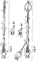
- FIG. 1 illustrates a catheter intended for use in dilatation of arteries, particularly peripheral arteries.
- the catheter includes an elongate flexible shaft 10 having a proximal end (to the left) and a distal end (to the right).
- the shaft 10 is formed from an appropriate polymeric material.
- the shaft may be formed from a composite of nylon and polyether block amide (PEBAXTM) or any polyamide based elastomer.
- PEBAXTM polyether block amide
- the catheter also may be formed to include different polymeric inner and outer layers, as in a coextrusion technique.
- the inner layer may be formed from a high lubricity material such as nylon and the outer material may be formed from a urethane material.
- a coextruded shaft the inner layer may be formed from a high lubricity material such as nylon and the outer material may be formed from a urethane material.
- the shaft 10 is formed to define an inner lumen 12.
- the catheter includes a luer fitting 14 attached to the proximal end of the shaft 10.
- a dilatation balloon 16 is mounted to the distal end of the shaft 10.
- the balloon 16 may be made as described in U.S. Patent 4,490,421 to Levy, the disclosure of which is hereby incorporated by reference.
- the fitting 14 at the proximal end of the catheter is adapted to be connected to an inflation and deflation device (such as a syringe) by which the balloon 16 may be inflated and deflated through the lumen 12.
- a core wire 18 is disposed within and extends the length if the lumen 12.
- the proximal end of the core wire is securely attached to the luer fitting 14 at the proximal end of the catheter with an appropriate adhesive, such as cyanoacrylate.
- the core wire also may be incorporated and integrally attached to the fitting by insert molding.
- the distal end of the core wire 18 protrudes distally beyond the end of the shaft 10 and terminates in an enlarged tip 20.
- the tip 20 may be molded from the same or similar polymeric material as that from which the shaft 10 is formed. the distal end of the core wire 18 extends through the balloon 16 and is secured to the tip 20.
- the balloon includes central cylindrical portion 16a, a pair of tapering cone sections 16b and a pair of cylindrical smaller diameter neck sections 16c that define the ends of the balloon 16.
- the balloon is attached to the catheter as by adhesively bonding the neck 16c at the proximal end of the balloon to the distal end of the catheter shaft 10 and by adhesively bonding the distal neck 16c to the catheter tip 20.
- a distal portion of the core wire 18 may be tapered, as indicated at 22 to provide the catheter with an increasing flexibility at its distal region.
- a core wire 18 formed from stainless steel may be of the order of between 0.012 ⁇ and 0.020 ⁇ (approximately) in diameter in order to aid materially in the torque transmission for the catheter.
- the torque transmission is achieved in a relatively simple construction but without the requirement for the more labor intensive layer-by-layer build up procedure and, in particular, without the requirement for incorporating a braided tube into the construction of the catheter wall.
- Progressively increased flexibility in the distal direction may also be achieved by a tapered core wire without the requirement of layer-by-layer construction.
- FIG. 2 illustrates another type of catheter incorporating the invention.
- the embodiment of Fig. 2 relates to a steerable electrode probe of the type that is intended to be inserted into a patient and manipulated into an intended body lumen, such as the region of the heart.
- the probe is intended to deliver electrical impulses to the internal site or alternatively, to provide electrical sensing functions in order to monitor the electrical activity of the particularly site in the body.
- the steerable electrode probe 24 of Fig. 2 includes an elongate flexible shaft 26 having an internal lumen 28 extending from its proximal to its distal end.
- the shaft is formed from an appropriate polymeric material and may be extruded.
- a fitting, in the form of an electrical connector 30 is securely attached to the proximal end of the shaft.
- the distal end of the catheter has a closed tip 32.
- a number of ring electrodes 34 are mounted to the distal end of the catheter and are exposed exteriorally on the catheter shaft.
- the electrode rings 34 are connected to the connector 30 by insulated circuit wires 36 that extend through the lumen 28 of the catheter shaft 26.
- the probe includes an elongate core wire 38 disposed within the lumen 28.
- the core wire 38 is attached at its proximal end to the connector 30 and at its distal end to the closed tip portion 32 of the catheter.
- the core wire 38 is sufficiently torsionally rigid so that it may transmit torque from the proximal end to the distal end of the catheter.
- the distal portion of the core wire 38 preferably is tapered, as suggested, at 40.
- a probe so made will display a high degree of torque transmission but without requiring the labor intensive layer-by-layer construction that has been typical of prior such catheters and probes. If the core wire is tapered, the probe will also display progressively increased flexibility in the distal direction. It is to be noted that with previous mapping probes, it has been common practice to incorporate a helical braid in the wall of the catheter in order to be able to transmit torque from the proximal to the distal end of the catheter. The inclusion of the braided layer necessarily results in a thicker wall than with the present invention. By omitting the braid, the present invention results in a catheter having a desirably lowered outer diameter and profile.
- FIG. 3 illustrates another type of catheter with which the present invention may be used.
- This catheter is intended to be used in angiographic applications, to deliver radiographic contrast liquid to a blood vessel to facilitate fluoroscopic visualization of the blood vessel.
- the catheter is provided with an elongate flexible shaft 42 which may be extruded from an appropriate polymeric material.
- the shaft is formed to include two lumens, including a fluid lumen 44 through which radiographic contrast liquid may be injected, and a core wire lumen 46.
- a luer fitting 48 is securely attached to the proximal end of the shaft 42 and provides a means by which contrast liquid can be injected into the fluid lumen 44.
- the fluid lumen 44 is open at the distal tip of the shaft 42, terminating at tip and side hole orifices 50.
- the core wire lumen 46 which contains a core wire 52 is contained within the wall of the shaft 42 so as to miximize the cross-sectional flow area of the fluid lumen 44. In angiographic catheters it is important that the catheter be able to deliver a relatively large volume of radiographic contrast liquid. A larger fluid lumen 44, therefore, is desirable.
- the catheter being intended to accommodate high flow rates.
- High flow rates of radiopaque contrast liquids are important in order that the blood vessel or other body lumen being investigated is fully and effectively filled with a high concentration of radiopaque contrast liquid which will be highly visible under X-ray fluoroscopy.
- the cross-sectional flow area of the fluid lumen may be miximized.
- a core wire as in the present invention, it is unnecessary to use a torque transmitting braid in the wall of the catheter. As a result, the wall may be thinner which provides capability for increasing the cross-sectional area of the fluid lumen 44.
- the core wire 52 is secured at its proximal end to the luer fitting 48.
- the distal end of the core wire which may be tapered as indicated at 54, also is secured within the wall of the catheter as by adhesive. Additionally, if the core wire is tapered, it is possible to provide progressively increased flexibility in the distal directlon without requiring a layer-by-layer construction.
- the lumen 46 may be formed to be slightly larger in diameter, for example, about 0.001 ⁇ , than the diameter of the core wire to enable the core wire to be slipped into the lumen.
- the lumen Before inserting the core wire into the lumen, the lumen may be filled with an adhesive.
- a small temporary hole may be formed through the side wall of the catheter in communication with the distal end of the lumen 46 either to enable air to escape when adhesive is injected into the lumen from its proximal end or to enable adhesive to be injected directly into the distal end of the lumen through the side hole.
- the core wire may be attached securely within its lumen without the use of a separate adhesive by heating the catheter while the core wire is in place to a degree sufficient to cause the inner surface of the core wire lumen to become tacky and adhere to the core wire. During such heat bonding a mandrel should be inserted through other lumen(s) of the catheter to assure their integrity.
- FIG. 4 shows another type of catheter incorporating the present invention in the form of a steerable flow directed catheter.
- a flow directed catheter typically is provided with a balloon at the distal end and it is the purpose of the balloon to be carried with the blood flow to the desired location in the blood vessel.
- this embodiment of the catheter includes an elongate flexible shaft 56 that may be formed from an extruded polymeric material.
- the shaft typically will include a relatively large diameter fluid lumen 58 that extends the length of the shaft 56 and terminates in outlet orifices 60 at the distal part of the shaft.
- the shaft 56 also includes an inflation lumen 62 (FIG.
- a Y-fitting 66 is mounted to the shaft in the region of its proximal end and includes an inflation leg 68 which terminates in a luer fitting 70.
- the luer fitting 70 is intended to be connected to an inflation and deflation device, such as a syringe (not shown) to inflate and deflate the balloon 64.
- the proximal end of the main shaft terminates in another luer fitting 72 which is securely attached to the proximal end of the shaft 56.
- the shaft 56 also includes a core wire lumen 74 that extends from the proximal end of the shaft toward the distal end.
- the core wire lumen 74 receives a core wire 76.
- the proximal end of the core wire is securely attached to the luer fitting 72.
- the distal end of the core wire 76 which may be tapered as indicated at 78 is attached securely to the distal portion of the catheter shaft as described above.
- the catheter benefits from the present invention by incorporating a core wire to impart torsional rigidity to the catheter in that it omits the need for braids and the like, thereby resulting in a thinner wall for the catheter.
- the core wire also can provide progressively increased flexibility in the distal direction without the requirement of changing the configuration of layers of material.
- the invention provides a simple, yet effective, means for enhancing the torque transmission capabilities of a wide variety of catheters. It also provides a means to vary the flexibility of the catheter by a simple construction. In particular, it also provides a simplified technique for manufacture that is less labor intensive and less costly than with prior techniques. The invention avoids the use of torque transmitting braids and the like.
Landscapes
- Health & Medical Sciences (AREA)
- Life Sciences & Earth Sciences (AREA)
- Heart & Thoracic Surgery (AREA)
- Engineering & Computer Science (AREA)
- Biophysics (AREA)
- Pulmonology (AREA)
- Child & Adolescent Psychology (AREA)
- Anesthesiology (AREA)
- Biomedical Technology (AREA)
- Hematology (AREA)
- Animal Behavior & Ethology (AREA)
- General Health & Medical Sciences (AREA)
- Public Health (AREA)
- Veterinary Medicine (AREA)
- Media Introduction/Drainage Providing Device (AREA)
Applications Claiming Priority (2)
| Application Number | Priority Date | Filing Date | Title |
|---|---|---|---|
| US58352890A | 1990-09-17 | 1990-09-17 | |
| US583528 | 1990-09-17 |
Publications (1)
| Publication Number | Publication Date |
|---|---|
| EP0476807A1 true EP0476807A1 (fr) | 1992-03-25 |
Family
ID=24333474
Family Applications (1)
| Application Number | Title | Priority Date | Filing Date |
|---|---|---|---|
| EP91305840A Withdrawn EP0476807A1 (fr) | 1990-09-17 | 1991-06-27 | Cathéters orientables à noyau en fil |
Country Status (4)
| Country | Link |
|---|---|
| US (2) | US5318041A (fr) |
| EP (1) | EP0476807A1 (fr) |
| JP (2) | JPH04226675A (fr) |
| IE (1) | IE912877A1 (fr) |
Cited By (11)
| Publication number | Priority date | Publication date | Assignee | Title |
|---|---|---|---|---|
| US5318525A (en) * | 1992-04-10 | 1994-06-07 | Medtronic Cardiorhythm | Steerable electrode catheter |
| US5397304A (en) * | 1992-04-10 | 1995-03-14 | Medtronic Cardiorhythm | Shapable handle for steerable electrode catheter |
| EP0595308A3 (fr) * | 1992-10-30 | 1995-05-17 | Pameda Nv | Cathéter à échange rapide. |
| US5445148A (en) * | 1992-04-10 | 1995-08-29 | Medtronic Cardiorhythm | Intracardiac electrical potential reference catheter |
| US5531690A (en) * | 1992-10-30 | 1996-07-02 | Cordis Corporation | Rapid exchange catheter |
| US5879324A (en) * | 1997-03-06 | 1999-03-09 | Von Hoffmann; Gerard | Low profile catheter shaft |
| US6312374B1 (en) | 1997-03-06 | 2001-11-06 | Progenix, Llc | Radioactive wire placement catheter |
| US7458955B2 (en) | 1997-03-11 | 2008-12-02 | Owens Warren D | Catheter having insertion control mechanism |
| US9028441B2 (en) | 2011-09-08 | 2015-05-12 | Corpak Medsystems, Inc. | Apparatus and method used with guidance system for feeding and suctioning |
| US9131956B2 (en) | 2005-01-13 | 2015-09-15 | Corpak Medsystems, Inc. | Tubing assembly and signal generator placement control device and method for use with catheter guidance systems |
| CN113768556A (zh) * | 2020-06-09 | 2021-12-10 | 上海交通大学医学院附属新华医院 | 一种内置式微型球囊关节撑开装置 |
Families Citing this family (88)
| Publication number | Priority date | Publication date | Assignee | Title |
|---|---|---|---|---|
| ES2043289T3 (es) | 1989-09-25 | 1993-12-16 | Schneider Usa Inc | La extrusion de capas multiples como procedimiento para hacer balones de angioplastia. |
| US5195969A (en) | 1991-04-26 | 1993-03-23 | Boston Scientific Corporation | Co-extruded medical balloons and catheter using such balloons |
| USD355031S (en) | 1992-04-20 | 1995-01-31 | Terumo Kabushiki Kaisha | Catheter |
| JP2770689B2 (ja) * | 1992-11-30 | 1998-07-02 | 日本ゼオン株式会社 | バルーンカテーテル |
| US5396902A (en) * | 1993-02-03 | 1995-03-14 | Medtronic, Inc. | Steerable stylet and manipulative handle assembly |
| US5431168A (en) * | 1993-08-23 | 1995-07-11 | Cordis-Webster, Inc. | Steerable open-lumen catheter |
| US6896842B1 (en) | 1993-10-01 | 2005-05-24 | Boston Scientific Corporation | Medical device balloons containing thermoplastic elastomers |
| JP3577082B2 (ja) | 1993-10-01 | 2004-10-13 | ボストン・サイエンティフィック・コーポレーション | 熱可塑性エラストマーから成る医療装置用バルーン |
| US5505699A (en) * | 1994-03-24 | 1996-04-09 | Schneider (Usa) Inc. | Angioplasty device |
| US5458639A (en) * | 1994-08-05 | 1995-10-17 | Medtronic, Inc. | Catheter balloon distal bond |
| US5827272A (en) * | 1995-08-07 | 1998-10-27 | Medtronic Cardiorhythm | Simplified torquing electrode catheter |
| US6371943B1 (en) * | 1997-09-08 | 2002-04-16 | Epimed International, Inc. | Spring tip needle combination |
| US6475187B1 (en) * | 1998-03-04 | 2002-11-05 | Scimed Life Systems, Inc. | Convertible catheter incorporating distal force transfer mechanism |
| US6413228B1 (en) | 1998-12-28 | 2002-07-02 | Pro Duct Health, Inc. | Devices, methods and systems for collecting material from a breast duct |
| US20050228367A1 (en) * | 1999-01-25 | 2005-10-13 | Marwan Abboud | Leak detection system for catheter based medical device |
| US6400992B1 (en) | 1999-03-18 | 2002-06-04 | Medtronic, Inc. | Co-extruded, multi-lumen medical lead |
| US6585717B1 (en) | 1999-06-15 | 2003-07-01 | Cryocath Technologies Inc. | Deflection structure |
| US7004936B2 (en) * | 2000-08-09 | 2006-02-28 | Cryocor, Inc. | Refrigeration source for a cryoablation catheter |
| US6471694B1 (en) | 2000-08-09 | 2002-10-29 | Cryogen, Inc. | Control system for cryosurgery |
| US6450948B1 (en) | 1999-11-02 | 2002-09-17 | Vista Medical Technologies, Inc. | Deflecting tip for surgical cannula |
| JP4347486B2 (ja) * | 2000-01-24 | 2009-10-21 | 辰雄 金重 | 留置カテーテル |
| US6482172B1 (en) | 2000-02-09 | 2002-11-19 | Jeffrey J. Thramann | Flow-by channel catheter and method of use |
| US7947059B2 (en) | 2000-03-02 | 2011-05-24 | Boston Scientific Scimed, Inc. | Multilayer medical device |
| US7033326B1 (en) | 2000-12-29 | 2006-04-25 | Advanced Bionics Corporation | Systems and methods of implanting a lead for brain stimulation |
| US6716207B2 (en) * | 2001-05-22 | 2004-04-06 | Scimed Life Systems, Inc. | Torqueable and deflectable medical device shaft |
| US8295945B1 (en) | 2001-05-29 | 2012-10-23 | Boston Scientific Neuromodulation Corporation | Neural stimulation lead fixation |
| US7099718B1 (en) | 2001-05-29 | 2006-08-29 | Advanced Bionics Corporation | Neural stimulation lead fixation |
| US7983766B1 (en) * | 2001-05-29 | 2011-07-19 | Boston Scientific Neuromodulation Corporation | Method of securing a neural stimulation lead |
| US6575920B2 (en) | 2001-05-30 | 2003-06-10 | Scimed Life Systems, Inc. | Distal tip portion for a guide wire |
| US6863678B2 (en) * | 2001-09-19 | 2005-03-08 | Advanced Cardiovascular Systems, Inc. | Catheter with a multilayered shaft section having a polyimide layer |
| FR2837693B1 (fr) * | 2002-03-27 | 2004-06-11 | Nmt Neurosciences Implants Fra | Catheter ballon |
| US7488339B2 (en) * | 2002-10-21 | 2009-02-10 | Boston Scientific Scimed, Inc. | Multilayer medical device |
| US7819866B2 (en) * | 2003-01-21 | 2010-10-26 | St. Jude Medical, Atrial Fibrillation Division, Inc. | Ablation catheter and electrode |
| US6951675B2 (en) * | 2003-01-27 | 2005-10-04 | Scimed Life Systems, Inc. | Multilayer balloon catheter |
| ATE427763T1 (de) * | 2003-02-26 | 2009-04-15 | Boston Scient Ltd | Ballonkatheter |
| US7101362B2 (en) * | 2003-07-02 | 2006-09-05 | St. Jude Medical, Atrial Fibrillation Division, Inc. | Steerable and shapable catheter employing fluid force |
| US7235070B2 (en) * | 2003-07-02 | 2007-06-26 | St. Jude Medical, Atrial Fibrillation Division, Inc. | Ablation fluid manifold for ablation catheter |
| US7166099B2 (en) * | 2003-08-21 | 2007-01-23 | Boston Scientific Scimed, Inc. | Multilayer medical devices |
| US7738993B2 (en) * | 2003-10-10 | 2010-06-15 | Boston Scientific Scimed, Inc. | Extrusion of articles |
| US20050209673A1 (en) * | 2004-03-04 | 2005-09-22 | Y Med Inc. | Bifurcation stent delivery devices |
| US8491636B2 (en) | 2004-03-23 | 2013-07-23 | Medtronic Cryopath LP | Method and apparatus for inflating and deflating balloon catheters |
| US7727228B2 (en) | 2004-03-23 | 2010-06-01 | Medtronic Cryocath Lp | Method and apparatus for inflating and deflating balloon catheters |
| US20050273096A1 (en) * | 2004-05-27 | 2005-12-08 | Roop John A | Anchoring introducer sheath with distal slots for catheter delivery and translation |
| US7717875B2 (en) * | 2004-07-20 | 2010-05-18 | St. Jude Medical, Atrial Fibrillation Division, Inc. | Steerable catheter with hydraulic or pneumatic actuator |
| US7691095B2 (en) | 2004-12-28 | 2010-04-06 | St. Jude Medical, Atrial Fibrillation Division, Inc. | Bi-directional steerable catheter control handle |
| US8583260B2 (en) | 2004-12-28 | 2013-11-12 | St. Jude Medical, Atrial Fibrillation Division, Inc. | Long travel steerable catheter actuator |
| US8858495B2 (en) | 2004-12-28 | 2014-10-14 | St. Jude Medical, Atrial Fibrillation Division, Inc. | Five degree of freedom ultrasound catheter and catheter control handle |
| US7783359B2 (en) * | 2005-01-05 | 2010-08-24 | Boston Scientific Neuromodulation Corporation | Devices and methods using an implantable pulse generator for brain stimulation |
| US7809446B2 (en) * | 2005-01-05 | 2010-10-05 | Boston Scientific Neuromodulation Corporation | Devices and methods for brain stimulation |
| US8273285B2 (en) | 2005-01-10 | 2012-09-25 | St. Jude Medical, Atrial Fibrillation Division, Inc. | Steerable catheter and methods of making the same |
| US8206345B2 (en) * | 2005-03-07 | 2012-06-26 | Medtronic Cryocath Lp | Fluid control system for a medical device |
| US7591784B2 (en) * | 2005-04-26 | 2009-09-22 | St. Jude Medical, Atrial Fibrillation Division, Inc. | Bi-directional handle for a catheter |
| US7819868B2 (en) * | 2005-06-21 | 2010-10-26 | St. Jude Medical, Atrial Fibrilation Division, Inc. | Ablation catheter with fluid distribution structures |
| US7465288B2 (en) * | 2005-06-28 | 2008-12-16 | St. Jude Medical, Atrial Fibrillation Division, Inc. | Actuation handle for a catheter |
| US8777929B2 (en) * | 2005-06-28 | 2014-07-15 | St. Jude Medical, Atrial Fibrillation Division, Inc. | Auto lock for catheter handle |
| US8271094B1 (en) * | 2005-09-30 | 2012-09-18 | Boston Scientific Neuromodulation Corporation | Devices with cannula and electrode lead for brain stimulation and methods of use and manufacture |
| US7891382B2 (en) * | 2005-12-16 | 2011-02-22 | Mercury Plastics, Inc. | Overmolded and bendable position-retaining tubing |
| US20070167972A1 (en) * | 2006-01-17 | 2007-07-19 | Euteneuer Charles L | Balloon apparatus and methods |
| US20070167876A1 (en) * | 2006-01-17 | 2007-07-19 | Euteneuer Charles L | Occluding guidewire and methods |
| US20070167877A1 (en) * | 2006-01-17 | 2007-07-19 | Euteneuer Charles L | Medical catheters and methods |
| US7906066B2 (en) * | 2006-06-30 | 2011-03-15 | Abbott Cardiovascular Systems, Inc. | Method of making a balloon catheter shaft having high strength and flexibility |
| US8382738B2 (en) * | 2006-06-30 | 2013-02-26 | Abbott Cardiovascular Systems, Inc. | Balloon catheter tapered shaft having high strength and flexibility and method of making same |
| US7583999B2 (en) | 2006-07-31 | 2009-09-01 | Cranial Medical Systems, Inc. | Multi-channel connector for brain stimulation system |
| US20080167628A1 (en) * | 2007-01-05 | 2008-07-10 | Boston Scientific Scimed, Inc. | Stent delivery system |
| US8403885B2 (en) | 2007-12-17 | 2013-03-26 | Abbott Cardiovascular Systems Inc. | Catheter having transitioning shaft segments |
| WO2009086512A2 (fr) * | 2007-12-28 | 2009-07-09 | Boston Endoscopic Engineering Corp. | Fil guide remplaçable à ballon pour extraction d'un corps étranger |
| WO2009157818A1 (fr) * | 2008-06-27 | 2009-12-30 | St. Jude Medical Ab | Ensemble comprenant un fil médical implantable et son procédé d’implantation |
| US11298113B2 (en) | 2008-10-01 | 2022-04-12 | Covidien Lp | Device for needle biopsy with integrated needle protection |
| US9186128B2 (en) | 2008-10-01 | 2015-11-17 | Covidien Lp | Needle biopsy device |
| US8968210B2 (en) * | 2008-10-01 | 2015-03-03 | Covidien LLP | Device for needle biopsy with integrated needle protection |
| US20110190662A1 (en) * | 2008-10-01 | 2011-08-04 | Beacon Endoscopic Corporation | Rapid exchange fna biopsy device with diagnostic and therapeutic capabilities |
| US9782565B2 (en) | 2008-10-01 | 2017-10-10 | Covidien Lp | Endoscopic ultrasound-guided biliary access system |
| US9332973B2 (en) | 2008-10-01 | 2016-05-10 | Covidien Lp | Needle biopsy device with exchangeable needle and integrated needle protection |
| US8444608B2 (en) | 2008-11-26 | 2013-05-21 | Abbott Cardivascular Systems, Inc. | Robust catheter tubing |
| US8052638B2 (en) | 2008-11-26 | 2011-11-08 | Abbott Cardiovascular Systems, Inc. | Robust multi-layer balloon |
| US8391985B2 (en) | 2009-11-30 | 2013-03-05 | Boston Scientific Neuromodulation Corporation | Electrode array having concentric windowed cylinder electrodes and methods of making the same |
| US8295944B2 (en) | 2009-11-30 | 2012-10-23 | Boston Scientific Neuromodulation Corporation | Electrode array with electrodes having cutout portions and methods of making the same |
| US8440090B2 (en) | 2010-04-29 | 2013-05-14 | Abbott Cardiovascular Systems Inc. | Apparatus and method of making a variable stiffness multilayer catheter tubing |
| WO2012162661A1 (fr) | 2011-05-26 | 2012-11-29 | Abbott Cardiovascular Systems Inc. | Bout traversant pour un cathéter |
| US10849771B2 (en) | 2011-06-27 | 2020-12-01 | Boston Scientific Scimed, Inc. | Stent delivery systems and methods for making and using stent delivery systems |
| EP2768568B1 (fr) | 2011-10-18 | 2020-05-06 | Boston Scientific Scimed, Inc. | Cathéter à ballonnet à traversée intégrée |
| US8684963B2 (en) | 2012-07-05 | 2014-04-01 | Abbott Cardiovascular Systems Inc. | Catheter with a dual lumen monolithic shaft |
| CA2879565A1 (fr) * | 2012-07-19 | 2014-01-23 | Boston Scientific Scimed, Inc. | Embase de catheter de protection contre le rayonnement et procedes d'utilisation associes |
| CA2879882A1 (fr) | 2012-07-23 | 2014-01-30 | University Of Utah Research Foundation | Sonde urinaire a demeure |
| JP6311031B2 (ja) | 2013-11-11 | 2018-04-11 | ヨン チュル アン、 | バルーンカテーテル |
| US10080865B2 (en) | 2014-01-14 | 2018-09-25 | Cook Medical Technologies Llc | Multi-lumen catheters for small body vessel applications |
| US10675443B2 (en) | 2016-03-07 | 2020-06-09 | St. Jude Medical, Cardiology Division, Inc. | Medical device including an actuator restraining assembly |
| WO2025197364A1 (fr) * | 2024-03-18 | 2025-09-25 | 日本ライフライン株式会社 | Cathéter à électrode |
Citations (3)
| Publication number | Priority date | Publication date | Assignee | Title |
|---|---|---|---|---|
| US3995623A (en) * | 1974-12-23 | 1976-12-07 | American Hospital Supply Corporation | Multipurpose flow-directed catheter |
| EP0279958A1 (fr) * | 1987-01-06 | 1988-08-31 | Advanced Cardiovascular Systems, Inc. | Cathéter de dilatation rempli de liquide à faible diamètre |
| US4875481A (en) * | 1988-07-01 | 1989-10-24 | Cordis Corporation | Catheter with coiled wire attachment |
Family Cites Families (15)
| Publication number | Priority date | Publication date | Assignee | Title |
|---|---|---|---|---|
| US3769984A (en) * | 1971-03-11 | 1973-11-06 | Sherwood Medical Ind Inc | Pacing catheter with frictional fit lead attachment |
| US4033331A (en) * | 1975-07-17 | 1977-07-05 | Guss Stephen B | Cardiac catheter and method of using same |
| US4582181A (en) * | 1983-08-12 | 1986-04-15 | Advanced Cardiovascular Systems, Inc. | Steerable dilatation catheter |
| US4619263A (en) * | 1984-05-30 | 1986-10-28 | Advanced Cardiovascular Systems, Inc. | Adjustable rotation limiter device for steerable dilatation catheters |
| US4664113A (en) * | 1984-05-30 | 1987-05-12 | Advanced Cardiovascular Systems, Inc. | Steerable dilatation catheter with rotation limiting device |
| US4586923A (en) * | 1984-06-25 | 1986-05-06 | Cordis Corporation | Curving tip catheter |
| US4608986A (en) * | 1984-10-01 | 1986-09-02 | Cordis Corporation | Pacing lead with straight wire conductors |
| US4641654A (en) * | 1985-07-30 | 1987-02-10 | Advanced Cardiovascular Systems, Inc. | Steerable balloon dilatation catheter assembly having dye injection and pressure measurement capabilities |
| US4723936A (en) * | 1986-07-22 | 1988-02-09 | Versaflex Delivery Systems Inc. | Steerable catheter |
| CH670391A5 (fr) * | 1986-07-29 | 1989-06-15 | Sarcem Sa | |
| US4771778A (en) * | 1987-01-06 | 1988-09-20 | Advanced Cardiovascular Systems, Inc. | Steerable low profile balloon dilatation catheter |
| US4815478A (en) * | 1987-02-17 | 1989-03-28 | Medtronic Versaflex, Inc. | Steerable guidewire with deflectable tip |
| US4940062A (en) * | 1988-05-26 | 1990-07-10 | Advanced Cardiovascular Systems, Inc. | Guiding member with deflectable tip |
| US4955384A (en) * | 1989-05-11 | 1990-09-11 | Advanced Cardiovascular Systems, Inc. | Guiding member for vascular catheters with a flexible link distal section |
| US5119832A (en) * | 1989-07-11 | 1992-06-09 | Ravi Xavier | Epidural catheter with nerve stimulators |
-
1991
- 1991-06-27 EP EP91305840A patent/EP0476807A1/fr not_active Withdrawn
- 1991-08-07 JP JP3197764A patent/JPH04226675A/ja active Pending
- 1991-08-14 IE IE287791A patent/IE912877A1/en unknown
-
1992
- 1992-06-30 US US07/906,538 patent/US5318041A/en not_active Expired - Lifetime
- 1992-08-10 US US07/927,868 patent/US5277199A/en not_active Expired - Lifetime
-
2002
- 2002-04-30 JP JP2002128125A patent/JP2002360702A/ja active Pending
Patent Citations (3)
| Publication number | Priority date | Publication date | Assignee | Title |
|---|---|---|---|---|
| US3995623A (en) * | 1974-12-23 | 1976-12-07 | American Hospital Supply Corporation | Multipurpose flow-directed catheter |
| EP0279958A1 (fr) * | 1987-01-06 | 1988-08-31 | Advanced Cardiovascular Systems, Inc. | Cathéter de dilatation rempli de liquide à faible diamètre |
| US4875481A (en) * | 1988-07-01 | 1989-10-24 | Cordis Corporation | Catheter with coiled wire attachment |
Cited By (16)
| Publication number | Priority date | Publication date | Assignee | Title |
|---|---|---|---|---|
| US5318525A (en) * | 1992-04-10 | 1994-06-07 | Medtronic Cardiorhythm | Steerable electrode catheter |
| US5397304A (en) * | 1992-04-10 | 1995-03-14 | Medtronic Cardiorhythm | Shapable handle for steerable electrode catheter |
| US5445148A (en) * | 1992-04-10 | 1995-08-29 | Medtronic Cardiorhythm | Intracardiac electrical potential reference catheter |
| EP0595308A3 (fr) * | 1992-10-30 | 1995-05-17 | Pameda Nv | Cathéter à échange rapide. |
| US5531690A (en) * | 1992-10-30 | 1996-07-02 | Cordis Corporation | Rapid exchange catheter |
| AU694389B2 (en) * | 1992-10-30 | 1998-07-16 | Cordis Corporation | Rapid exchange catheter |
| US5879324A (en) * | 1997-03-06 | 1999-03-09 | Von Hoffmann; Gerard | Low profile catheter shaft |
| US6312374B1 (en) | 1997-03-06 | 2001-11-06 | Progenix, Llc | Radioactive wire placement catheter |
| US7458955B2 (en) | 1997-03-11 | 2008-12-02 | Owens Warren D | Catheter having insertion control mechanism |
| US9131956B2 (en) | 2005-01-13 | 2015-09-15 | Corpak Medsystems, Inc. | Tubing assembly and signal generator placement control device and method for use with catheter guidance systems |
| US9579488B2 (en) | 2005-01-13 | 2017-02-28 | Corpak Medsystems, Inc. | Tubing assembly and signal generator placement control device and method for use with catheter guidance systems |
| US9889277B2 (en) | 2005-01-13 | 2018-02-13 | Avent, Inc. | Tubing assembly and signal generator placement control device and method for use with catheter guidance systems |
| US10549074B2 (en) | 2005-01-13 | 2020-02-04 | Avent, Inc. | Tubing assembly and signal generation placement device and method for use with catheter guidance systems |
| US9028441B2 (en) | 2011-09-08 | 2015-05-12 | Corpak Medsystems, Inc. | Apparatus and method used with guidance system for feeding and suctioning |
| US9918907B2 (en) | 2011-09-08 | 2018-03-20 | Avent, Inc. | Method for electromagnetic guidance of feeding and suctioning tube assembly |
| CN113768556A (zh) * | 2020-06-09 | 2021-12-10 | 上海交通大学医学院附属新华医院 | 一种内置式微型球囊关节撑开装置 |
Also Published As
| Publication number | Publication date |
|---|---|
| JPH04226675A (ja) | 1992-08-17 |
| US5277199A (en) | 1994-01-11 |
| US5318041A (en) | 1994-06-07 |
| JP2002360702A (ja) | 2002-12-17 |
| IE912877A1 (en) | 1992-02-25 |
Similar Documents
| Publication | Publication Date | Title |
|---|---|---|
| US5277199A (en) | Core wire steerable catheters | |
| US7503904B2 (en) | Dual balloon telescoping guiding catheter | |
| JP2865428B2 (ja) | 高性能ブレードカテーテル | |
| US10569062B2 (en) | Low profile occlusion catheter | |
| US4559951A (en) | Catheter assembly | |
| US6648854B1 (en) | Single lumen balloon-tipped micro catheter with reinforced shaft | |
| EP1401525B1 (fr) | Catheter intravasculaire comportant une pointe multicouche | |
| JP3329464B2 (ja) | 可変的な堅さを有するバルーンカテーテル | |
| JP3224501B2 (ja) | 高性能のらせん巻カテーテル | |
| US6371943B1 (en) | Spring tip needle combination | |
| US6652508B2 (en) | Intravascular microcatheter having hypotube proximal shaft with transition | |
| EP0998955B1 (fr) | Cathéter à ballonnet à rigidité variable | |
| JPH1071208A (ja) | 遠位側に孔を備える、ねじれ耐性を有する編み組みカテーテル | |
| JP4544526B2 (ja) | カテーテル | |
| US20220249804A1 (en) | Deflectable Sheath With Inflatable Balloon | |
| JPH0352530Y2 (fr) | ||
| WO2023095838A1 (fr) | Cathéter |
Legal Events
| Date | Code | Title | Description |
|---|---|---|---|
| PUAI | Public reference made under article 153(3) epc to a published international application that has entered the european phase |
Free format text: ORIGINAL CODE: 0009012 |
|
| AK | Designated contracting states |
Kind code of ref document: A1 Designated state(s): BE DE ES FR GB IT NL |
|
| STAA | Information on the status of an ep patent application or granted ep patent |
Free format text: STATUS: THE APPLICATION IS DEEMED TO BE WITHDRAWN |
|
| 18D | Application deemed to be withdrawn |
Effective date: 19920926 |