EP0476819A1 - Pignon d'entraînement pour une scie à chaîne - Google Patents
Pignon d'entraînement pour une scie à chaîne Download PDFInfo
- Publication number
- EP0476819A1 EP0476819A1 EP91307150A EP91307150A EP0476819A1 EP 0476819 A1 EP0476819 A1 EP 0476819A1 EP 91307150 A EP91307150 A EP 91307150A EP 91307150 A EP91307150 A EP 91307150A EP 0476819 A1 EP0476819 A1 EP 0476819A1
- Authority
- EP
- European Patent Office
- Prior art keywords
- sprocket
- portions
- links
- saw chain
- rim
- Prior art date
- Legal status (The legal status is an assumption and is not a legal conclusion. Google has not performed a legal analysis and makes no representation as to the accuracy of the status listed.)
- Withdrawn
Links
Images



Classifications
-
- B—PERFORMING OPERATIONS; TRANSPORTING
- B27—WORKING OR PRESERVING WOOD OR SIMILAR MATERIAL; NAILING OR STAPLING MACHINES IN GENERAL
- B27B—SAWS FOR WOOD OR SIMILAR MATERIAL; COMPONENTS OR ACCESSORIES THEREFOR
- B27B17/00—Chain saws; Equipment therefor
- B27B17/08—Drives or gearings; Devices for swivelling or tilting the chain saw
-
- F—MECHANICAL ENGINEERING; LIGHTING; HEATING; WEAPONS; BLASTING
- F16—ENGINEERING ELEMENTS AND UNITS; GENERAL MEASURES FOR PRODUCING AND MAINTAINING EFFECTIVE FUNCTIONING OF MACHINES OR INSTALLATIONS; THERMAL INSULATION IN GENERAL
- F16H—GEARING
- F16H7/00—Gearings for conveying rotary motion by endless flexible members
- F16H7/06—Gearings for conveying rotary motion by endless flexible members with chains
Definitions
- This invention relates to a drive sprocket for a chain saw, that is, to a drive sprocket for propelling a saw chain around a guide bar on a chain saw.
- Motorized chain saws utilize a drive sprocket coupled to an output shaft of the drive motor to propel an endless saw chain around an elongate guide bar.
- a saw chain as contemplated herein is an endless sequence of links pivotably connected by rivets, the links including alternating center drive links and paired side links. Certain of the side links have outwardly extended cutting portions and are referred to as cutting links, and the other side links are referred to as tie straps.
- Drive sprockets are in general of two different types and the present invention is directed to the type referred to as a rim sprocket.
- the conventional rim type drive sprocket is circular in side view and has formed pockets open to the periphery and extending radially inwardly for receiving drive tangs that depend from the center drive links of the saw chain.
- the outer peripheral edges of the sprocket on either side of the pockets provide spaced rims which support the side links of the saw chain.
- the lower section of the side links whether they are cutter links or tie straps, have the same configured profile.
- the side links have, referring to the direction of travel, leading and trailing flat bottom support edges separated by a center notch. These support edges are sometimes referred to as leading and trailing footprints.
- the saw chain is entrained, under tension, around the peripheral edge of the elongate guide bar and the drive sprocket, and is propelled by engagement of the driven drive sprocket with the depending tangs of the drive links.
- the guide bar edge has a center groove in which the depending tangs of the drive links travel to guide the chain as it travels around the bar.
- the bottom support edges of the side links ride on the side rails on either side of the center groove.
- the saw chain is made up of short rigid links that take the shape of a polygon as the chain travels around the bar ends, whereas the rim sprocket provides a circular support edge for the chain.
- the lower front corner (the toe portion of the leading footprint) of each side link initially engages the circular support surface of the rim.
- the link rocks backward and in the process slides the point of engagement across the bottom edge of the leading footprint until the inner corners of both footprints (heel and toe portions, respectively) are engaged and supported on the sprocket rim.
- the preferred embodiment of the present invention provides a polygon configured rim sprocket, but in the present invention, the rotating flats are matched to the side links so that the corners between the flats are rotated under the side links.
- the corners of the polygon support the side links in a manner similar to the support provided by the prior circular rims.
- the difference from the prior sprockets is that the flat edges provide areas of relief at the point where previously the side link corners engaged the sprocket periphery.
- the polygon corners simply rotate under and into the side link notches with the preceding flats providing a relief area at that portion of the rim that would otherwise be impacted by the side link corner. This relationship largely obviates the hammering effect and reduces the tension variation.
- a motorized chain saw 10 includes an elongate guide bar 12 adjustably mounted on a housing 14.
- the axis of the guide bar 12 is aligned with a drive sprocket 16 which is coupled to an output shaft 18 of the saw 10.
- An endless articulated saw chain 22 is entrained around the guide bar 12 and the drive sprocket 16.
- the coupling of the drive sprocket 16 to the output shaft 18 of the chain saw 10 is well known to the art and therefore the details of this are not shown.
- the internal grooves 20 of the drive sprocket 16 mate with male splines of a drive hub on a centrifugal clutch in a known, conventional, manner.
- the sprocket of the invention has the shape of a polygon.
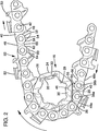
- the sprocket 16 shown in Figs. 2, 3 and 4 has on its periphery, seven sides 24 of equal length, angularly positioned at equal radial distances from the center of the sprocket, the sprocket thus being symmetrical relative to the sprocket center.
- the ends of each of the sides 24 are connected to an adjacent side 24 by a connecting arc 26.
- the sides 24 are chords of a circle, the circle having the same center point and radius as the connecting arcs 26.
- the flat sides 24 and the connecting arcs 26, thus cooperatively determine the periphery of the sprocket 16.
- the sprocket 16 has a central through bore 28, and female grooves 20 are formed in the sprocket 16 surrounding the bore 28.
- the sprocket 16 is constructed of two spaced parallel rims 34, 36 and sprocket teeth 32 confined between the rims.
- Receiving pockets 30 of a size and shape to receive the drive tangs 46 of the center drive links 40 of the saw chain 22 are formed in the sprocket 16 between the rims 34, 36 and between teeth 32.
- the pockets extend radially inward from the sides 24 and intersect with the center through bore 28.
- the pockets 30 are centrally positioned relative to the width of the sprocket, having a sufficient width to receive the width of the drive tangs 46 of the center drive links 40.
- a support rim 34 is thus provided on one side of each pocket 30 on the sprocket periphery and a rim 36 on the other side.
- Fig. 4 provides a comparison as between the sprocket of the present invention and the prior art circular sprocket illustrated as dash line 25.
- the flat sides 24 of the present sprocket are joined together by the arcuate segments of the circle of dash line 25.
- the present sprocket 16 is relieved to the extent of the areas 27, that is, the different between the full circle of dash line 25 and the underlying flat sides 24.
- the endless saw chain as previously described comprises alternating center links 40 and pairs of side links represented either by pairs of tie straps 48 or by a tie strap 48 and an opposed cutter link 50,52.
- the lower body portions of all of the side links are similar and are configured as illustrated in Fig. 6.
- the pivotal coupling or connection between the side links and center drive links is provided by rivets 38.
- the bottom edge configuration of the side links include a leading footprint 54 and a trailing footprint 60.
- the leading footprint 54 has a leading toe portion 56 and a heel 58.
- the trailing footprint 60 has corresponding toe and heel portions 62,64 respectively.
- FIG. 2 illustrates a tie strap 48a seated on a connecting corner or arc 26 of the sprocket periphery and a following tie strap 48b approaching the sprocket periphery.
- the rear rivet 38a of the tie strap 48a is moving in a direction dictated by its arc of movement about the axis of the sprocket. This arc of movement is essentially in line with the following straight reach of chain, and accordingly, the tie strap 48b is being drawn essentially in a straight line toward the sprocket periphery.
- the link would then rock back as the sprocket continues on a circular path around the sprocket center until the periphery of the sprocket enters the notch 66 to support the heel and toe (56 and 62) of the front and rear footprints (54,60).
- the provision of the relieved areas 27 on the sprocket periphery substantially increases the life of the sprocket 16.
- the hammering effect that undesirably accelerated wear due to the prior art sprocket-saw chain action has been largely eliminated.
- the oscillating action of the side link has been reduced and a more even chain tension can be achieved.
- the benefit of the invention is believed largely due to the result of the strategically located periphery relief areas 27.
- the relief areas enable the toe of the leading foot print to project through the circular path generated by the sprocket periphery which in the prior rim sprockets was co-incident with the sprocket periphely, indicated by dash line 25.
- Other configurations are possible and the flat segments are believed preferable primarily for manufacturing purposes.
- the scope of the invention is not limited to the embodiment disclosed but is defined by the claims appended hereto.
Landscapes
- Engineering & Computer Science (AREA)
- Life Sciences & Earth Sciences (AREA)
- Mechanical Engineering (AREA)
- General Engineering & Computer Science (AREA)
- Wood Science & Technology (AREA)
- Forests & Forestry (AREA)
- Sawing (AREA)
- Gears, Cams (AREA)
- Devices For Conveying Motion By Means Of Endless Flexible Members (AREA)
Applications Claiming Priority (2)
| Application Number | Priority Date | Filing Date | Title |
|---|---|---|---|
| US07/584,348 US5098348A (en) | 1990-09-18 | 1990-09-18 | Drive sprocket for a chain saw |
| US584348 | 1996-01-11 |
Publications (1)
| Publication Number | Publication Date |
|---|---|
| EP0476819A1 true EP0476819A1 (fr) | 1992-03-25 |
Family
ID=24336955
Family Applications (1)
| Application Number | Title | Priority Date | Filing Date |
|---|---|---|---|
| EP91307150A Withdrawn EP0476819A1 (fr) | 1990-09-18 | 1991-08-02 | Pignon d'entraînement pour une scie à chaîne |
Country Status (5)
| Country | Link |
|---|---|
| US (1) | US5098348A (fr) |
| EP (1) | EP0476819A1 (fr) |
| JP (1) | JPH04236850A (fr) |
| BR (1) | BR9102178A (fr) |
| CA (1) | CA2040526A1 (fr) |
Cited By (2)
| Publication number | Priority date | Publication date | Assignee | Title |
|---|---|---|---|---|
| WO2014143135A1 (fr) * | 2013-03-14 | 2014-09-18 | Blount, Inc. | Appareil, procédé et système d'orientation d'un maillon de chaîne de scie sur un pignon |
| WO2021107833A1 (fr) * | 2019-11-27 | 2021-06-03 | Husqvarna Ab | Pignon d'entraînement de dispositif de coupe par abrasion de type à flasques, agencement d'entraînement, dispositif de coupe par abrasion et procédé d'entraînement d'une chaîne de coupe par abrasion d'un dispositif de coupe par abrasion |
Families Citing this family (16)
| Publication number | Priority date | Publication date | Assignee | Title |
|---|---|---|---|---|
| US5303477A (en) * | 1992-11-10 | 1994-04-19 | Blount, Inc. | Multi-ring sprocket |
| SE502948C2 (sv) * | 1994-06-13 | 1996-02-26 | Sandvik Ab | Delad drivring för kedjesågar |
| US6428436B1 (en) * | 1999-04-27 | 2002-08-06 | Rexnord Corporation | Drive sprocket with relief areas |
| US7044025B2 (en) * | 2004-09-27 | 2006-05-16 | Blount, Inc. | Rim sprocket for chain saw |
| US20080011144A1 (en) * | 2006-07-13 | 2008-01-17 | Blount, Inc., A Limited Liability Company Of Delaware | Saw chain having multiple drive link configurations |
| US8746118B2 (en) | 2008-07-08 | 2014-06-10 | Blount, Inc. | Chain link sharpening method and apparatus |
| EP2490871B1 (fr) | 2009-10-21 | 2016-10-05 | Blount, INC. | Affûteur monté sur une barre |
| USD663602S1 (en) | 2010-01-21 | 2012-07-17 | Blount, Inc. | Saw chain sharpening stone and holder |
| WO2012122061A2 (fr) | 2011-03-04 | 2012-09-13 | Blount, Inc. | Procédé et appareil d'aiguisage de maillon de chaîne |
| SE536987C2 (sv) * | 2012-05-03 | 2014-11-25 | Jps Teknik Ab | Förfarande och arrangemang vid en motorsåg |
| DE102012010963A1 (de) * | 2012-05-31 | 2013-12-05 | Andreas Stihl Ag & Co. Kg | Arbeitsgerät mit Kettenraddeckel |
| US10265788B2 (en) | 2015-11-30 | 2019-04-23 | Scott D. Lynn | Chainsaw sharpening device, system, and method |
| USD843802S1 (en) * | 2018-03-14 | 2019-03-26 | Blount, Inc | Bumper drive link |
| USD842910S1 (en) * | 2018-03-14 | 2019-03-12 | Blount, Inc. | Cutter for saw chain |
| WO2022011349A1 (fr) * | 2020-07-10 | 2022-01-13 | Bean Gregory Vern | Systèmes de chaîne à maillons produisant des changements continus de vitesse et d'accélération |
| AT525220B1 (de) * | 2021-06-08 | 2023-07-15 | Prinz Gmbh | Schneidvorrichtung und Antriebsrad |
Citations (4)
| Publication number | Priority date | Publication date | Assignee | Title |
|---|---|---|---|---|
| US2602343A (en) * | 1949-11-26 | 1952-07-08 | Joy Mfg Co | Chain drive |
| US3491806A (en) * | 1965-12-03 | 1970-01-27 | Stihl Maschf Andreas | Sprocket wheel,especially for motor chain saws |
| US3683980A (en) * | 1971-02-26 | 1972-08-15 | Mcculloch Corp | Chain stabilizing chain saw sprockets |
| DE4022576A1 (de) * | 1989-07-17 | 1991-01-31 | Sandvik Ab | Antriebszahnrad fuer kettensaegen |
Family Cites Families (9)
| Publication number | Priority date | Publication date | Assignee | Title |
|---|---|---|---|---|
| US1671571A (en) * | 1924-12-15 | 1928-05-29 | Gustave A Carlson | Sash-regulating device |
| US1930466A (en) * | 1932-06-10 | 1933-10-17 | Newton K Bowman | Cutter chain for mining machines |
| US2000499A (en) * | 1932-08-08 | 1935-05-07 | Alvey Ferguson Co | Conveyer |
| US2387064A (en) * | 1942-06-16 | 1945-10-16 | Mark L Forrest | Chain saw |
| US2854294A (en) * | 1955-02-02 | 1958-09-30 | Schield Bantam Company | Crawler tumbler and track shoe |
| US3486574A (en) * | 1968-06-26 | 1969-12-30 | Harnischfeger Corp | Drive mechanism for crawler tracks |
| US3659908A (en) * | 1970-02-19 | 1972-05-02 | Edouard Martin Comellas | Track-engaging assembly |
| PL105657B1 (pl) * | 1975-06-04 | 1979-10-31 | Kolo lancuchowe zwlaszcza dla maszyn gorniczych | |
| WO1986003447A1 (fr) * | 1984-12-05 | 1986-06-19 | Fuji Blade Co. Ltd | Tronçonneuse |
-
1990
- 1990-09-18 US US07/584,348 patent/US5098348A/en not_active Expired - Lifetime
-
1991
- 1991-04-16 CA CA002040526A patent/CA2040526A1/fr not_active Abandoned
- 1991-05-28 BR BR919102178A patent/BR9102178A/pt unknown
- 1991-06-07 JP JP3136757A patent/JPH04236850A/ja active Pending
- 1991-08-02 EP EP91307150A patent/EP0476819A1/fr not_active Withdrawn
Patent Citations (4)
| Publication number | Priority date | Publication date | Assignee | Title |
|---|---|---|---|---|
| US2602343A (en) * | 1949-11-26 | 1952-07-08 | Joy Mfg Co | Chain drive |
| US3491806A (en) * | 1965-12-03 | 1970-01-27 | Stihl Maschf Andreas | Sprocket wheel,especially for motor chain saws |
| US3683980A (en) * | 1971-02-26 | 1972-08-15 | Mcculloch Corp | Chain stabilizing chain saw sprockets |
| DE4022576A1 (de) * | 1989-07-17 | 1991-01-31 | Sandvik Ab | Antriebszahnrad fuer kettensaegen |
Non-Patent Citations (1)
| Title |
|---|
| Product Engineering, Vol. 27, No. 11, 15 October 1956, New York, US, pages 22-23; E.I. RADZIMOVSKY: "Methods for reducing pulsations in chain drives", page 23, line 5 - line 11; figures 1,4. * |
Cited By (4)
| Publication number | Priority date | Publication date | Assignee | Title |
|---|---|---|---|---|
| WO2014143135A1 (fr) * | 2013-03-14 | 2014-09-18 | Blount, Inc. | Appareil, procédé et système d'orientation d'un maillon de chaîne de scie sur un pignon |
| US9038519B2 (en) | 2013-03-14 | 2015-05-26 | Blount, Inc. | Apparatus, method, and system for orienting a saw chain link on a sprocket |
| WO2021107833A1 (fr) * | 2019-11-27 | 2021-06-03 | Husqvarna Ab | Pignon d'entraînement de dispositif de coupe par abrasion de type à flasques, agencement d'entraînement, dispositif de coupe par abrasion et procédé d'entraînement d'une chaîne de coupe par abrasion d'un dispositif de coupe par abrasion |
| EP4065329A4 (fr) * | 2019-11-27 | 2024-01-17 | Husqvarna AB | Pignon d'entraînement de dispositif de coupe par abrasion de type à flasques, agencement d'entraînement, dispositif de coupe par abrasion et procédé d'entraînement d'une chaîne de coupe par abrasion d'un dispositif de coupe par abrasion |
Also Published As
| Publication number | Publication date |
|---|---|
| CA2040526A1 (fr) | 1992-03-19 |
| BR9102178A (pt) | 1992-04-28 |
| US5098348A (en) | 1992-03-24 |
| JPH04236850A (ja) | 1992-08-25 |
Similar Documents
| Publication | Publication Date | Title |
|---|---|---|
| US5098348A (en) | Drive sprocket for a chain saw | |
| US4425830A (en) | Anti-kickback saw chain | |
| KR960007074B1 (ko) | 크롤러 장치 | |
| EP0074207A2 (fr) | Guide-chaîne | |
| CA1202232A (fr) | Barbotin a extracteurs radiaux et sciures | |
| ATE201555T1 (de) | Messer für einen sichelmäher und sichelmäher | |
| US4816010A (en) | Sprocket with radial clearing means | |
| US4278301A (en) | Tread belt and drive having involute gear drive | |
| GB2067465A (en) | Saw chain for power chain saws | |
| JPS59500607A (ja) | チエ−ンソ−およびそのチエ−ンに関する改良 | |
| US3163052A (en) | Drive mechanism for chain saw | |
| US4562761A (en) | Articulated saw | |
| US4464964A (en) | Articulated saw | |
| US4970789A (en) | Sprocket nose guide bar for chain saws | |
| EP0332743A1 (fr) | Pignon d'entraînement pour scie à chaîne ayant des marques-indicateurs d'usure | |
| US5092211A (en) | Saw chain having cutter link with central pivot on bottom edge | |
| US4813325A (en) | Circular saw blade | |
| US4524519A (en) | Continuous loop flexible saw | |
| US6317989B1 (en) | Chain saw nose sprocket | |
| EP0478697A1 (fr) | Lame debrouissailleuse amelioree. | |
| US4484504A (en) | Saw chain with anti-kickback cutter link | |
| JPH09500857A (ja) | 湾曲エスカレータのための駆動機構 | |
| US6006629A (en) | Automatic chain sharpening device mounted on a chain saw | |
| JP2002037152A (ja) | 駆動タンブラ | |
| US3548897A (en) | Saw chain |
Legal Events
| Date | Code | Title | Description |
|---|---|---|---|
| PUAI | Public reference made under article 153(3) epc to a published international application that has entered the european phase |
Free format text: ORIGINAL CODE: 0009012 |
|
| AK | Designated contracting states |
Kind code of ref document: A1 Designated state(s): DE IT SE |
|
| STAA | Information on the status of an ep patent application or granted ep patent |
Free format text: STATUS: THE APPLICATION IS DEEMED TO BE WITHDRAWN |
|
| 18D | Application deemed to be withdrawn |
Effective date: 19920926 |