EP0476899B1 - Mécanisme de verrouillage de glissière par l'établissement de modes dans un lecteur de cassettes - Google Patents
Mécanisme de verrouillage de glissière par l'établissement de modes dans un lecteur de cassettes Download PDFInfo
- Publication number
- EP0476899B1 EP0476899B1 EP91308206A EP91308206A EP0476899B1 EP 0476899 B1 EP0476899 B1 EP 0476899B1 EP 91308206 A EP91308206 A EP 91308206A EP 91308206 A EP91308206 A EP 91308206A EP 0476899 B1 EP0476899 B1 EP 0476899B1
- Authority
- EP
- European Patent Office
- Prior art keywords
- slider
- brake
- lever
- biasing
- tape
- Prior art date
- Legal status (The legal status is an assumption and is not a legal conclusion. Google has not performed a legal analysis and makes no representation as to the accuracy of the status listed.)
- Expired - Lifetime
Links
Images


Classifications
-
- G—PHYSICS
- G11—INFORMATION STORAGE
- G11B—INFORMATION STORAGE BASED ON RELATIVE MOVEMENT BETWEEN RECORD CARRIER AND TRANSDUCER
- G11B15/00—Driving, starting or stopping record carriers of filamentary or web form; Driving both such record carriers and heads; Guiding such record carriers or containers therefor; Control thereof; Control of operating function
- G11B15/18—Driving; Starting; Stopping; Arrangements for control or regulation thereof
- G11B15/22—Stopping means
-
- G—PHYSICS
- G11—INFORMATION STORAGE
- G11B—INFORMATION STORAGE BASED ON RELATIVE MOVEMENT BETWEEN RECORD CARRIER AND TRANSDUCER
- G11B15/00—Driving, starting or stopping record carriers of filamentary or web form; Driving both such record carriers and heads; Guiding such record carriers or containers therefor; Control thereof; Control of operating function
- G11B15/02—Control of operating function, e.g. switching from recording to reproducing
- G11B15/10—Manually-operated control; Solenoid-operated control
- G11B15/106—Manually-operated control; Solenoid-operated control mechanically operated
Definitions
- the present invention relates to a slider lock mechanism for a tape player for establishing a plurality of modes such as play and stop modes by moving a slider slidable along a chassis, and in particular to a lock mechanism for a slider for setting the modes.
- Tape players have a mode in which one member should be brought into a pressure contact with another member.
- a tape loading post for pulling out a tape from a tape cassette to achieve a tape loading is brought into a pressure contact with a positioning block, or a pinch roller is brought into a pressure contact with a capstan so that a tape is pinched therebetween.
- a limiter switch is usually used as pressure contact means if such a pressure contact is necessary.
- a limiter spring is disposed between a movable member moved by a motor and the like and a support member for supporting the pinch roller thereon and spring biasing force is generated in the limiter switch by slightly moving the moving member by the motor even after the pinch roller is brought into contact with the capstan so that the pressure contact therebetween is continued by the spring biasing force.
- a worm gear is inserted into a rotation transmission system for transmitting the rotation of a motor to the moving member or, dedicated electromagnetic actuators are comparatively often used for locking one of members of the transmission system.
- the moving member for moving a support member which supports a member which is in a pressure contact with the other member often includes a mode establishing slider, that is, a slider which is rectilinearly slidably supported on a chassis and is moved to a given position to establish a given mode.
- a considerable load is imposed upon the slider for moving the members to be in a pressure contact and the support member which supports these members and upon the transmission system of the slider drive unit for moving the slider under such a pressure contact condition.
- a suitable tension is usually applied to the tape and a strong force is applied to the tape in a depth direction on a position where the tape is pinched between the pinch roller and the capstan. Therefore, it is necessary to eliminate such a pressure contact for preventing components of the mechanism and the tape from being distorted and damaged due to high load imposed for an extended period of time when a power failure occurs in such a mode.
- locking by said lock means is automatically released to release the pressure contact condition at least when a power failure occurs in a pressure contact condition.
- GB-A-2,070,317 discloses a slider lock mechanism in accordance with the preamble of claim 1 and in which a solenoid is used to control rotation of a mode selecting gear.
- a slider lock mechanism for setting the modes of a tape player comprising:
- the present invention is embodied in a mode setting slider lock mechanism in a rotary head type audio tape recorder 1 (hereinafter referred to as "R-DAT").
- the R-DAT 1 includes a sub-chassis 3 disposed in front (the right and lower side of the drawing as viewed in Fig. 1 will referred to as front side. Left and upper, left and lower and right and upper sides of the drawing as viewed in Fig. 6 will be referred to as rear, left and right sides, respectively. Directions are defined based on these positions) or a main chassis 2 and therebelow so that it faces the chassis 2 in a parallel relationship therewith.
- Two reel drive shaft assembly supporting rods 4A and 4B which are separated apart each other in right and left directions are provided on the sub-chassis 3 so that they erect therefrom.
- Reel drive shaft assemblies 5A and 5B are rotatably supported on the reel drive shaft assembly supporting rods 4A and 4B.
- Each of the reel drive shaft assemblies 5A and 5B comprises a gear unit 6 having two input gears, which forms the lower end thereof and a reel engagement hub 7 which forms the upper end of the reel drive shaft assembly gear unit 6 and the reel engagement hub 7 are coaxially disposed.
- the upper portions of the reel drive shaft assemblies 5A and 5B pass through holes 2a and 2a bored in the main chassis 2 and project upward therefrom.
- a rocking gear 8 is adapted to rotate the reel drive shaft assemblies 5A and 5B in a tape taking-up direction when it is engaged with either one of the reel drive shaft assemblies 5A and 5B.
- the rocking gear 8 is rotatably supported by a rocking lever 9 which is supported on the sub-chassis 3 so that the rocking gear is rotatable in substantially right and left directions.
- the rocking gear 8 is rotated by a reel drive shaft assembly rotating motor 10.
- the reel drive shaft assemblies 5A and 5B are rotated at a relatively low speed in a play mode for recording or play back and are rotated at a high speed in a fast running mode for fast forwarding or rewinding of the tape.
- a head drum 11 is disposed at the rear end on the upper surface of the main chassis 2 and comprises a fixed drum 11a, a rotary drum 11b which is coaxial with the drum 11a and a rotary magnetic head 11c which is disposed on the outer periphery of a gap between the two drums 11a and 11b and is rotatable together with the rotary drum 11b.
- Fixed tape guides 12A and 13B are provided on the main chassis 2 so that they erect therefrom.
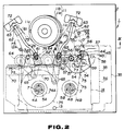
- Cassette positioning pins 13 on which a tape cassette 14 (refer to fig. 2) is disposed are provided on the chassis 2.
- a capstan 15 is rotatably supported on a capstan housing (not shown) secured to the main chassis 2.
- the capstan 15 is positioned apart from the right fixed tape guide 12B in front and slightly right direction as viewed from an upper point and is rotated by a capstan motor 16 (refer to Fig. 9) provided below the main chassis 2.
- a brake mechanism 17 is adapted to brake one or both of the reel drive shaft assemblies 5A and 5B in a given mode and comprises two brake levers, one for each of the drive shaft assemblies 5A and 5B and an electromagnetic actuator and a brake release lever, etc.
- a brake lever 18 for the S side reel drive shaft assembly (hereinafter referred to as S side brake lever) and a brake lever 19 for the T side reel drive shaft assembly (hereinafter referred to as T side brake lever), each comprises a horizontal flat plate-like main portion 20, a cylindrical portion 21 which is linked to the left or right end of the main portion of the S or T side brake lever 18 or 19 and a brake shoe 22 secured to the central and lower surface of the rear side portion of the main portion 20.
- the cylindrical portions 21 are supported by support rods 23 erecting from the sub-chassis 3 so that the levers 18 and 19 are swingable in forward and rearward direction on positions in substantial front of the reel drive shaft assemblies 5A and 5B.
- the brake shoes 22 are positioned on substantially same level of the gear units 6.
- a tension spring 24 is tensioned between the spring engagements 20a of the brake lever 18 and 19.
- the tensioning force of the tension spring 24 applies counterclockwise and clockwise (as viewed from an upper position) rotational forces upon the S and T side brake lever 18 and 19 respectively.
- the S and T side brake levers 18 and 19 brake the S and T side reel drive shaft assemblies 5A and 5B by the pressure contact of the brake shoes 22 with the gear units 6 of the S and T side reel drive shaft assemblies 5A and 5B, respectively.
- a brake release lever 25 is extended in right and left directions.
- a support rod 26 erecting upon the front end portion of the sub-chassis 3 is inserted into a support hole 25a formed in the middle of the lever 25 so that the lever 25 is rotatable around the rod 26.
- the lever 25 is formed with an substantially U-shaped link 27 at left end thereof and is formed with a biasing pin 28 extending vertically at the right end thereof.
- An electromagnetic actuator 29 is mounted upon the sub-chassis 3 at the left and portion thereof so that the tip end of a piston rod 30 projects forward beyond a shield frame 31.
- the link 27 of the brake release lever 25 is engaged with a diameter reduced portion 30a formed on the front end of the piston rod 30.
- the biasing pin 28 of the brake release lever 25 is loosely fitted at the upper end portion thereof into a hole 32 formed in the main portion 20 of the T side brake lever 19.
- the counterclockwise rotation of the lever 19 causes a biasing portion 33 projecting in a left direction from the rear portion of the rotary end of the lever to bias a portion to be biased 34 provided on the rotary end of the S side brake lever 18 and facing the biasing portion 33 of the T side brake lever 19 in a substantially forward direction so that the S side brake lever is rotated in a clockwise direction.
- This causes the brake shoes 22 of the brake levers 18 and 19 to move to a break release position separated from the gear units 6 of the drive shaft assemblies 5A and 5B (refer to Fig. 11) so that braking of the reel drive shaft assemblies 5A and 5B are released.
- the S side brake lever 18 is held on the brake release position for a period of time from an initial mode before a tape loading is performed until the tape loading is completed by a mode slider which will be described hereafter. Accordingly, only the T side reel drive assembly 5B is braked for that period of time.
- the mode slider 35 is supported on the lower surface of the main chassis 2 so that it is movable in right and left directions and is moved to predetermined positions for moving a loading block, pinch rollers and moving guides to predetermined positions which will be hereinafter described so that various modes are selectively established.
- the mode slider 35 comprises a main portion 36 which has a shape which is rectangular and elongated in right and left direction as viewed from an upper position and a control portion 37 which projects rearward from the right end portion of the rear side edge of the main portion 36.
- the main portion 36 and the control portion 37 are integrally formed of a synthetic resin.
- the main portion 36 is formed with a relatively large opening 38 which is located in the middle of a width direction (in forward and rearward directions), elongated holes to be guided 39 which are located in the front side edges and are extended in right and left directions, and a rack 40 formed on the lower surface of the main portion, which is located in the right end portion thereof and is extended in right and left directions.
- the mode slider 35 is thus supported on the lower surface of the main chassis 2 so that it is movable in right and left directions over a predetermined range.
- the intermediate portions of the reel drive shaft assemblies 5A and 5B are inserted through the opening 38.
- the control portion 37 is formed into a substantially L-shape as viewed from an upper position and is formed at the right end thereof with a spring arranging hole 41 which is elongated in forward and rearward directions and is formed in the substantially middle of the rear end thereof with a restriction hole 42 which is rectangular and elongated in forward and rearward directions.
- a front side 43 (hereinafter referred to as holding portion) of a rear half portion is formed into a flat side extending in right and left directions and a cut groove 44 (hereinafter referred to as "biasing portion” ) which is formed to extend in forward and rearward directions has a front end which opens to the right end of the holding portion 43.
- the holding portion 43 and the biasing portion 44 from a control cam 45 for performing a position control of a rotary lever which will be described hereafter.
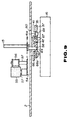
- a slider drive unit 46 is provided on the right end of the sub-chassis 3.
- a motor 47 is a drive source of the slider drive unit 46 and is secured to the lower surface of the right and rear end of the sub-chassis 3.
- An output gear 48 in the form of a spur gear which is thick in an axial direction and is secured to a portion of a rotary shaft of the motor 47 projecting upward beyond the sub-chassis 3.
- Each of transmission gears 49, 50, 51 and 52 is in the form of a spur gear and comprises a set of two large and small coaxial gears which are integrally formed and is individually and rotatably supported on one of the gear supporting shafts 53 axially erecting upward from the upper surface of the sub-chassis 3.
- a larger gear 49a of a first transmission gear 49a of a first transmission gear 49 which is located on the lowermost level is meshed with the output gear 48.
- a larger gear 50a of a second transmission gear 50 which is located on the second lower level is meshed with a smaller gear 49b of the first transmission gear 49.
- a larger gear 51a of a third transmission gear 51 which is located on the third lower level is meshed with a smaller gear 50b of a second transmission gear 50.
- a larger gear 52a of a fourth transmission gear 52 which is located on the uppermost level is meshed with a smaller gear 51b of a third transmission gear 51.
- a pinion gear which forms a smaller gear of the fourth gear 52 is meshed with a rack 40 of a mode slider 35 from the rear side of the slider 35.
- the rotation of the motor 47 is transmitted to the pinion gear 52b after being reduced by a gear train including the output gear 48 and the first to fourth transmission gears 49, 50, 51 and 52. Advancing of the rack 40 by the pinion gear 52b moves the mode slider 35.
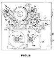
- the mode slider 35 is moved among a position represented by a dotted line in Fig. 2, that is, an initial position which is a left extremity of the movement range thereof, a position shown in Fig. 3, that is, a play time position which is a right extremity of the movement range thereof and a position represented by a two dot and chain line, that is, a stop time position offset in a slightly left direction from the play time position.
- a tape loading is achieved by the movement of the mode slider 35 from the initial position to the step time position.
- a stop mode is established by the movement of the slider 35 to the stop time position.
- a rotary lever 54 supports a pinch roller 55 and a movable guide 56.
- the rotary lever 54 is in the form of an inverted V-shaped plate which opens toward the rear side thereof as viewed from an upper position when it is on a position shown in Fig. 10A.
- the rotary lever 54 is widely formed at the rear end of the left half thereof and is formed with two erecting support shafts 57 which are spaced apart in right and left directions at the rear end of the left half thereof.
- the pinch roller 55 and the movable guide 56 rotatably supported by the support shafts 57, respectively.
- the rear end of the right half of the lever 54 is bent in a left direction and a pin to be biased 58 is suspended therefrom.
- the rotary lever 54 is supported on a support shaft 59 projectingly provided on the main chassis 2 in the substantial middle of the right half thereof so that the lever 35 is rotatably in a horizontal direction around the shaft 59.
- the pin to be biased 58 passes through a hole 60 formed in the main chassis 2 (illustration thereof is omitted in Figs. 2 and 3) so that most of the pin 58 projects downward beyond the hole 60.
- the width of the biasing portion 44 of the control cam 45 is substantial same as the diameter of the pin to be biased 58.
- Loading blocks 61 are adapted to perform the tape loading and comprises movable bases 62 and loading posts 63 which are erectingly provided on the movable bases 62.
- the movable bases 62 are supported on the main chassis 2 so that they are moved along elongated guide grooves 2b formed in the main chassis 2 on the right and left sides of the head drum 11.
- Loading gears 64 are rotatably supported on the lower surface of the main chassis 2 and are meshed with a rack of a rack plate supported by the mode slider 35, which will be hereafter described.
- Loading arms 65 can be extended and retracted by the rotation of the loading gears 64 provided on the base end of the arms 65.
- the loading arms 64 are rotatably linked with the movable bases 62 of the loading blocks 61 at the tip end thereof.
- a pressure contact lever 66 which is supported by the mode slider 35 is adapted to bring the pinch roller 55 into a pressure contact with the capstan 15 in the play mode.
- the pressure contact lever 66 is formed into a substantial ⁇ -shaped plate which opens forward as viewed from an upper position and is provided with a stopper pin 67 on the lower surface thereof at an corner in which a right side portion is connected to an intermediate portion.
- biasing portion The length of the left side portion in forward and rearward direction is slightly longer than that of the left half of the control portion 39 of the mode slider 35.
- a front half portion 68 of the right side edge of the left side portion (hereinafter referred to as “biasing portion") is slanted so that it is displaced to the left as it is extended to the front end thereof.
- the thus formed pressure contact lever 66 is positioned to overlap the upper surface of the control portion of the mode slider 35.
- a cylindrical pivot pin 66a suspended from the lower surface of the rear end portion of the left side portion is rotatably inserted into a support hole 37a formed at the left end of the rear end portion of the control portion 37 so that the pressure contact lever 66 is rotatably supported on the mode slider 35.
- the stopper pin 67 is positioned in the restriction hole 42. Accordingly, the rotation of the pressure contact lever 66 is restricted in a given range of the rotational angle and the counterclockwise rotation of the lever is prevented when the stopper pin 67 is in the standby position in which the pin 67 is abutted upon the rear side edge of the restriction hole 42.
- a tension spring 69 is positioned in a spring arrangement hole 41 formed in the control portion 37 and is tensioned between a spring engaging portion 41a positioned at the rear end of the spring arrangement hole 41 of the control portion 37 and a spring engaging hole 66b formed at the front end of the right side portion of the pressure contact lever 66.
- the pressure contact lever 66 is biased to rotate in a counterclockwise direction as viewed from an upper position by the tension of the tension spring 69 and is normally held on the stand-by position when it is not biased in a clockwise direction.
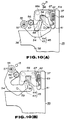
- the rotary lever 54 is moved among a first position shown in Fig. 10(A) represented by a solid line in Fig. 2, a second position shown in Figs. 10(D) and 2, and a third position shown in Fig. 10(B) and represented by a two dot and chain line in Fig. 2.
- the mode slider 35 when the mode slider 35 is on the initial position, the movement of the pin to be biased 58 is prevented by the biasing portion 44 of the control cam 45 so that the rotary lever 54 is held on the first position.
- the pinch roller 55 is on the position apart from the capstan 15 by an angle of substantially 90° in a counterclockwise direction and the movable guide 56 is positioned on the substantially right side of the pinch roller 55.
- the left side edge of the biasing portion 44 of the control cam 45 biases the pin to be biased 58 in a right direction.
- the rotary lever 50 is thus rotated in a clockwise direction as viewed from an upper position to move the mode slider 35 to the stop time position.
- the pin to be biased 58 rides on the right end portion of the holding portion 43 of the control cam 45 as shown in Fig. 10(B). This prevents the rotary lever 54 from being rotated toward the first position. In such manner, the rotary lever 54 is moved to and held on the third position.
- the pinch roller 55 is positioned in the substantially left and front side of the capstan 15 in the vicinity thereof.
- the movable guide 56 is positioned on a position slightly remote from the capstan 15 in a forward direction.
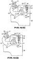
- the biasing portion 68 of the pressure contact lever 66 abuts on the pin to be biased 58 immediately after the commencement of the movement for biasing the pin to be biased 58 in a substantially right direction.
- the pressure contact lever 66 is held on the stand-by position by the tension of the tension spring 69 for a period of time until this time.
- the mode slider 35 is further moved in a right direction from this position to reach the play time position so that the pinch roller 55 is brought into a pressure contact with the capstan 15.
- the rotary lever 54 is prevented from being rotated in a clockwise direction by the abutment of the pinch roller 55 upon the capstan 15.
- a portion of the biasing portion 68 of the pressure contact lever 66 which is in contact with the pin to be biased 58 is thus prevented from moving in a right direction by the pin to be biased 58.
- the pressure contact lever 66 is rotated in a clockwise direction against the tension of the tension spring 69 so that the stopper pin 67 is released from the rear side edge of the restriction hole 42.
- the tension exerted by the tension spring 69 will act as a force to rotate the rotary lever 54 in a clockwise direction via the pressure contact lever 66.
- the pinch roller 55 is brought into a pressure contact with the capstan 15 and the positions of the rotary lever 54 and the movable guide 56 are stably held by this tension.
- Rack plates 70 are supported on the upper surface of the rear end portion of the main portion 36 of the mode slider 35 so that they are movable in right and left directions within a given range.
- the rack plates 70 are biased to move in a right direction by tension springs 71 (refer to Fig. 6) tensioned between the main portion 36 and the plates 70.
- tension springs 71 biased between the main portion 36 and the plates 70.
- Teeth 70a of the rack plates 70 are meshed with the loading gear 64. Accordingly, the loading gear 64 is rotated when the rack plates 70 are moved. This causes the loading arms 65 to be extended or retracted.
- the loading arms 65 are retracted as shown in Fig. 2. This causes loading blocks 61 to be held on the stand-by position represented by a solid line in Fig. 2, that is, a position in which the blocks 61 are juxtaposed with the pinch roller 55 and the movable guide 56.
- the loading gears 64 are rotated in a counterclockwise direction by rack plates 70 so that the loading arms 65 are extended as shown in Fig. 3.
- the loading blocks 61 are then moved to a loading completion position in which they abut upon catcher 72 secured to the upper surface of the main chassis 2 as shown in Fig. 2.
- the rack plates 70 are moved in an integral manner with the mode slider until this time.
- the rack plates 70 is moved leftward relative to the mode slider 35. That is, since more extension of the loading arms 65 is prevented when the loading blocks 61 abut upon the catcher 72 so that the loading gears 64 are prevented from being rotated in a counterclockwise direction and rightward movement of the rack plates 70 meshed with the loading gears 64 is also prevented. The rack plates 70 are thus moved leftward relative to the mode slider 35 so that the tension springs 71 are extended.
- Tension of the tension springs 71 will act as a force to bias the loading blocks 61 upon the catchers 72 via the rack plates 70, the loading gears 64 and the loading arms 65 under this condition. This causes the loading blocks 61 to be brought into a pressure contact with the catchers 72.
- the mode sliders 35 are on the initial position. Accordingly, the rotary lever 51 is held on the first position by the biasing portion 44 of the control cam 45 and the loading blocks 61 are held on the stand-by position. The side brake lever 18 is held on the brake release position. Therefore, the S side reel drive shaft assembly 51 can be rotated.
- the pinch roller 55, movable guide 56 and the loading posts 63 are relatively positioned in a tape pulling recess 73 provided on the front side of a cassette case of the tape cassette 14 and a supply side tape reel 74A (hereinafter referred to "S reel") which the tape cassette 14 has and a take-up side tape reel 74B (hereinafter referred to as "T reel”) are engaged with the reel engaging shafts 7 of the two reel drive shaft assemblies 5A and 5B, respectively.
- S reel supply side tape reel
- T reel take-up side tape reel
- a portion of the magnetic tape 75 which has been positioned along the front face of the tape pulling recess 73 is pulled out by a given amount from the S reel 74 by being pulled by the loading posts 63, the pinch roller 55 and the movable guide 56 which move rearward.
- the thus pulled out magnetic tape 75 is passed through a tape path represented by a small two dot and chain line in Fig. 2.
- a tape path represented by a small two dot and chain line in Fig. 2.
- the magnetic tape 75 exits from the S reel 74A, it is wound around the left side fixed tape guide 12 and the loading post 63 in this order.
- the magnetic tape is wound around the loading post 63, it is turned forward and wound around the outer periphery of the head drum 11 over a given winding angle and is turned rearward is then wound around the right side loading post 63.
- the tape 75 is then turned forward again, it is wound around the right side fixed tape guide 12 and the movable guide 56 in this order and is taken up by the T reel.
- the position restriction of the S side brake lever 18 by the mode slider 35 is released simultaneously with that the mode slider 35 reaches the stop time position.
- the S side brake lever 18 is then moved to the brake position.
- This condition is the stop mode.
- Fast running of the tape for fast feeding or rewinding is performed by rotating the reel drive shaft assemblies 5A or 5B after the electromagnetic actuator 29 is energized to move the brake levers 18 and 19 to the brake release position for releasing the brake on the reel drive shaft assemblies 5A and 5B. That is, when the fast feeding of the tape is performed, the T side reel drive shaft assembly 5B with which the T reel 74B is engaged is rotated at a high speed in a clockwise as viewed from an upper position.
- the reel drive shaft assembly with which the S reel is engaged is rotated at a high speed in a counterclockwise direction as viewed from an upper position so that it is run at a high speed in such a direction the magnetic tape 75 is pulled out from the T reel 74B and taken up by the S reel 74A.
- the mode slider 35 When an instruction for establish a play mode for recording or play back, the mode slider 35 in moved to the play time posifion. Simultaneously with the arrival of the mode slider 35 at the play time position, electromagnetic actuator 29 is energized to move the brake levers 18 and 29 to the brake release position. This causes the loading blocks 61 to be brought into a pressure contact with the catchers 72 and the rotary lever 54 is moved to the second position so that the pinch roller 55 is brought into a pressure contact with the capstan 15 so that the magnetic tape 75 is pinched therebetween.
- the magnetic tape 75 is run at a constant speed by the rotating capstan 15 and the rotating pinch roller 55 which is in a pressure contact therewith.
- the thus running magnetic tape is taken up by the T reel 74B or the S reel 74A.
- the rotary magnetic heads 11c scans the recording surface of the magnetic tape 75 so that recording of signals on and reproducing of the recorded signals from the magnetic tape 75 is performed.
- the mode slider 35 When an instruction to switch the play mode to the stop mode is issued, the mode slider 35 is moved to the stop time position so that the pressure contact lever 66 is returned to the stand-by position and the rotary lever 54 is rotated in a counterclockwise direction to return to the third position.
- the mode slider 35 When an instruction to switch the stop mode to the initial mode is issued, the mode slider 35 is moved to the initial position so that the rotary lever 54 is returned to the first position and the loading arms 65 are retracted to return the loading blocks 61 to the stand-by position. At this time, the magnetic tape 75 which has been pulled out from the cassette tape 14 is rewound by the S reel 74.
- the loading blocks 61 are in pressure contact with the catchers 72 by the tension of the tension springs 71, and the pinch roller 55 is in a pressure contact with the tension of the tension spring 69 of the pinch roller 55.
- the slider lock mechanism 76 comprises the electromagnetic actuator 29, the brake release lever 25 and a lock lever 77 which are included in the brake mechanism 17.
- the lock lever 77 comprises a main portion which is generally elongated in right and left directions, having a slightly bent right half portion, a cylindrical boss 79 which is short in an axial direction thereof and projects from the upper surface of the rear end portion of an widely formed intermediate portion of the main portion 78 on a position offset in a left direction, a spring supporting pin 80 which erects on the upper surface of the main portion 78 on a position offset toward the left end thereof, a brake shoe supporting pin 82 erecting on the right end of the main portion 78, and a leaf spring 78 which has a main portion extending in parallel with the intermediate portion of the rear side edge of the main portion 78 and a left end integral to the main portion 78.
- a cylindrical brake shoe 84 made of a rubber material is fitted on a brake shoe mounting pin 82 and the hole 79a of the boss 79 opens to the lower surface of the main portion 78.
- a torsional spring 85 comprises a coil portion 85a which is fitted on the spring support pin 80 of the lock lever 77, an arm 85b which is biased on the front side thereof at the tip end thereof by the boss 79 and the other arm 85c which is biased on the front side at the intermediate thereof by a spring abutment 81.
- a lever support shaft is erectingly provided on the upper surface of the front end portion of the sub-chassis 3 on a position offset leftward from the gear support shaft 53 for supporting the second transmission gear 50 of the slider drive unit 46.
- the lever support shaft 88 is inserted into the hole 79a of the boss 79 so that the lock lever 77 is rotatably supported by the lever support shaft 86.
- the tip end of the leaf spring 83 is springly contact on front side thereof the lower end portion of the gear support shaft 53 which supports the second transmission gear 50 so that the lock lever 77 is biased to rotate in a clockwise direction as viewed from an upper position.
- the tip end of the other arm 85c of the torsional spring 85c is springly contact on the front side thereof with the lower end of the biasing pin 28 of the brake release lever 25.
- the electromagnetic actuator 29 is energized when the magnetic tape is run from the stop mode or when the mode slider 35 reaches the play time position to complete the establishment of the play mode.
- This causes the brake release lever 25 to be rotated in a clockwise direction to move the brake levers 18 and 19 to the brake release position.
- the brake release lever 25 is rotated in a clockwise direction when the magnetic tape 75 begins to run from the condition that the made slider 35 is on the stop time position or when the mode slider 35 reaches at the play time position so that the pinch roller 55 is brought into a pressure contact with the capstan 15.
- the brake release lever 25 is slightly rotated in a clockwise direction after the brake shoe 84 is brought into a pressure contact with the first transmission gear 49 to prevent the lock lever 77 from more rotating in a counterclockwise direction.
- the position of the rack 40 of the mode slider 35 is fixed.
- the mode slider 35 is locked of the position in interest, that is, the stop time position or play time position. Locking on the play time position is performed against the returning force.
- the mode slider 35 Since the mode slider 35 is locked in such a manner, the mode slider is stably held on the loading completion position in which the loading blocks 61 are brought into an abutment on the catchers 72 when fast feeding and rewinding of the tape is performed.
- condition of the pressure contact of the pinch roller 55 with the capstan 15 is stably held.
- Locking of the mode slider 35 is released when an instruction to release the mode in which fast feeding or rewinding of the tape is performed is issued, when an instruction to release the play mode is issued, or when a power interruption occurs in these modes.
Landscapes
- Transmission Devices (AREA)
- Braking Arrangements (AREA)
Claims (11)
- Mécanisme de blocage de coulisseau destiné au réglage des modes d'un appareil d'enregistrement-lecture sur bande, comprenant :un dispositif à coulisseau (35) qui peut coulisser le long d'un châssis (2) pour l'établissement de l'un de plusieurs modes de fonctionnement suivant la position du dispositif à coulisseau,un dispositif de rappel (69, 71) destiné à rappeler le dispositif à coulisseau vers une première position,un dispositif (46) d'entraînement de coulisseau destiné à transformer une force d'entraînement d'un moteur en une force de déplacement du dispositif à coulisseau par l'intermédiaire de plusieurs pignons rotatifs, etun dispositif de freinage (76) destiné à bloquer le dispositif à coulisseau dans une seconde position malgré la force de rappel du dispositif de rappel,caractérisé en ce quele dispositif de freinage freine l'un au moins des pignons rotatifs (49a) par excitation du dispositif électromagnétique de manoeuvre (29), etle dispositif de freinage est libéré lors de la désexcitation du dispositif électromagnétique de manoeuvre (29).
- Mécanisme de blocage de coulisseau selon la revendication 1, dans lequel le dispositif à coulisseau comprend :un dispositif (70, 64) d'entraînement de chargement destiné à entraîner un dispositif (61-63) de chargement de bande qui tire une bande magnétique logée dans au moins une cassette de manière que la bande s'enroule autour d'un dispositif à tête d'enregistrement et/ou lecture, etun dispositif (45) d'entraînement de levier de pincement destiné à entraîner un dispositif (66) à levier de pincement qui supporte un galet de pincement (55) qui, pendant l'utilisation, est destiné à exercer une pression contre un cabestan (15), la bande magnétique, lorsqu'elle est chargée, se trouvant entre le cabestan et le galet de pincement, le dispositif à coulisseau pouvant coulisser pratiquement en direction parallèle à une droite reliant les centres de deux ensembles à arbre d'entraînement de bobine (4A, 4B).
- Mécanisme de blocage de coulisseau selon la revendication 2, dans lequel le dispositif de chargement de bande comprend :un organe coulissant à crémaillère (70), etun premier organe à ressort (71) placé entre le dispositif à coulisseau (35) et l'organe coulissant à crémaillère afin qu'il déplace le dispositif de chargement de bande par rapport à un organe d'accrochage (72) monté sur le châssis (2), l'organe d'accrochage étant destiné à être en butée contre le dispositif de chargement de bande (61-63) en position de fin de chargement de bande.
- Mécanisme de blocage de coulisseau selon la revendication 2 ou 3, dans lequel le dispositif d'entraînement de levier de pincement comporte :un levier rotatif (54) de contact sous pression destiné à entraîner le dispositif à levier de pincement lors du déplacement du dispositif à coulisseau (35), etun second organe à ressort (69) placé entre le dispositif à coulisseau et le levier de contact sous pression de manière que le galet de pincement (55) soit mis en contact sous pression avec un cabestan (15).
- Mécanisme de blocage de coulisseau selon l'une quelconque des revendications précédentes, dans lequel le dispositif à coulisseau (35) est mobile entre au moins une position initiale, la première position représentant une position d'arrêt, et la seconde position représentant une position d'enregistrement ou de lecture.
- Mécanisme de blocage de coulisseau selon la revendication 5, dans lequel le dispositif (61-63) de chargement de bande est entraîné par le dispositif (64, 70) d'entraînement de chargement pendant que le dispositif à coulisseau se déplace entre la position initiale et la première position.
- Mécanisme de blocage de coulisseau selon l'une quelconque des revendications précédentes, dans lequel le dispositif de rappel comprend le second organe à ressort (69) ou un second organe à ressort destiné à mettre le galet de pincement (55) en contact sous pression avec le cabestan (15) lorsque le dispositif à coulisseau (35) est dans la seconde position.
- Mécanisme de blocage de coulisseau selon l'une quelconque des revendications précédentes, dans lequel le dispositif de rappel comprend le premier organe à ressort (71) ou un premier organe à ressort destiné à mettre le bloc (61) de chargement de bande en contact sous pression avec l'organe ou un organe d'accrochage (72) lorsque le dispositif à coulisseau (35) est dans la seconde position, l'organe d'accrochage étant destiné à être en butée contre le dispositif de chargement de bande (61-63) en position de fin de chargement de bande.
- Mécanisme de blocage de coulisseau selon l'une quelconque des revendications précédentes, dans lequel le dispositif de freinage (76) comprend :un dispositif (17) à levier de frein qui peut être en butée contre un ensemble à arbre d'entraînement de bobine,un dispositif (77, 85) de rappel de frein destiné à rappeler le dispositif à levier de frein afin qu'il mette normalement ce dispositif en butée contre l'ensemble à arbre d'entraînement de bobine, etun levier (25) de libération de frein destiné à déplacer le dispositif à levier de frein à distance de l'ensemble à arbre d'entraînement de bobine malgré la force du dispositif de rappel de frein, si bien que l'organe électromagnétique de manoeuvre (29) est excité afin qu'il entraîne le dispositif à levier de libération de frein et qu'il s'écarte de l'ensemble à arbre d'entraînement de bobine.
- Mécanisme de blocage de coulisseau selon l'une quelconque des revendications précédentes, dans lequel le dispositif de freinage comprend :un premier dispositif (77) à levier de frein qui peut être en butée contre l'un de plusieurs pignons (49),un dispositif (83) de rappel de frein destiné à rappeler le premier dispositif à levier de frein dans un sens qui assure normalement la séparation du dispositif à levier de frein, etun second dispositif (25) à levier de frein destiné à venir au contact du premier dispositif à levier de frein et à le déplacer malgré la force de rappel de manière que le premier dispositif à levier de frein soit mis en butée contre l'un des pignons, si bien que l'organe électromagnétique de manoeuvre (29) est excité afin qu'il déplace le second dispositif à levier de manière qu'il mette le premier dispositif à levier de frein en butée contre l'un des pignons.
- Mécanisme de blocage de coulisseau selon la revendication 10 lorsqu'elle dépend de la revendication 9, dans lequel le second dispositif (25) à levier de frein comprend le dispositif à levier de libération de frein.
Applications Claiming Priority (2)
| Application Number | Priority Date | Filing Date | Title |
|---|---|---|---|
| JP246619/90 | 1990-09-17 | ||
| JP24661990A JP3173782B2 (ja) | 1990-09-17 | 1990-09-17 | テーププレーヤにおけるスライダーロック機構 |
Publications (3)
| Publication Number | Publication Date |
|---|---|
| EP0476899A2 EP0476899A2 (fr) | 1992-03-25 |
| EP0476899A3 EP0476899A3 (en) | 1993-05-26 |
| EP0476899B1 true EP0476899B1 (fr) | 1996-11-27 |
Family
ID=17151100
Family Applications (1)
| Application Number | Title | Priority Date | Filing Date |
|---|---|---|---|
| EP91308206A Expired - Lifetime EP0476899B1 (fr) | 1990-09-17 | 1991-09-09 | Mécanisme de verrouillage de glissière par l'établissement de modes dans un lecteur de cassettes |
Country Status (3)
| Country | Link |
|---|---|
| US (1) | US5126909A (fr) |
| EP (1) | EP0476899B1 (fr) |
| JP (1) | JP3173782B2 (fr) |
Families Citing this family (7)
| Publication number | Priority date | Publication date | Assignee | Title |
|---|---|---|---|---|
| JP2664281B2 (ja) * | 1990-11-09 | 1997-10-15 | 株式会社日立製作所 | 磁気記録再生装置 |
| JP2906741B2 (ja) * | 1991-06-13 | 1999-06-21 | 松下電器産業株式会社 | 磁気記録再生装置 |
| DE4292188C2 (de) * | 1991-07-01 | 1998-04-16 | Funai Electric Co | Vorrichtung zum Auswählen eines Bandspulen-Steuermodus |
| GB9116265D0 (en) * | 1991-07-27 | 1991-09-11 | Normalair Garrett Ltd | Cassette recorders |
| KR940006382B1 (ko) * | 1992-07-08 | 1994-07-20 | 삼성전자 주식회사 | 자기기록 및/또는 재생장치 |
| KR0176551B1 (ko) * | 1995-12-22 | 1999-04-15 | 김광호 | 자기 기록/재생장치 |
| JP3915916B2 (ja) * | 2003-01-06 | 2007-05-16 | ソニー株式会社 | 記録再生装置 |
Family Cites Families (5)
| Publication number | Priority date | Publication date | Assignee | Title |
|---|---|---|---|---|
| JPS56117355A (en) * | 1980-02-22 | 1981-09-14 | Victor Co Of Japan Ltd | Controller of power application time for solenoid for operatig mode switching for tape recorder |
| US4754347A (en) * | 1985-02-28 | 1988-06-28 | Sanyo Electric Co., Ltd. | Brake mechanism for magnetic tape reel mounts in a video tape recorder |
| US4841391A (en) * | 1986-08-27 | 1989-06-20 | Canon Kabushiki Kaisha | Rotary head type recording and/or reproducing apparatus having mode selecting mechanism |
| US4907110A (en) * | 1987-01-19 | 1990-03-06 | Canon Kabushiki Kaisha | Tape loading device for recording and/or reproducing apparatus |
| US4975793A (en) * | 1987-02-26 | 1990-12-04 | Mitsubishi Denki Kabushiki Kaisha | Tape loading mechanism for causing a length of tape to travel along a rotary head drum |
-
1990
- 1990-09-17 JP JP24661990A patent/JP3173782B2/ja not_active Expired - Fee Related
-
1991
- 1991-08-13 US US07/744,702 patent/US5126909A/en not_active Expired - Fee Related
- 1991-09-09 EP EP91308206A patent/EP0476899B1/fr not_active Expired - Lifetime
Also Published As
| Publication number | Publication date |
|---|---|
| JP3173782B2 (ja) | 2001-06-04 |
| EP0476899A3 (en) | 1993-05-26 |
| JPH04125839A (ja) | 1992-04-27 |
| US5126909A (en) | 1992-06-30 |
| EP0476899A2 (fr) | 1992-03-25 |
Similar Documents
| Publication | Publication Date | Title |
|---|---|---|
| US4547823A (en) | Mode changing apparatus | |
| CA1321020C (fr) | Appareil d'enregistrement et de lecture magnetiques | |
| EP0488714B1 (fr) | Mécanisme de changement de mode pour un appareil de reproduction à bande | |
| EP0476899B1 (fr) | Mécanisme de verrouillage de glissière par l'établissement de modes dans un lecteur de cassettes | |
| CA1329260C (fr) | Appareil d'enregistrement et/ou de lecture a tete tournante utilisant une cassette de bande magnetique | |
| KR880003724Y1 (ko) | 진동 아이들러 기구 | |
| US4538753A (en) | Tape recorder | |
| US4209145A (en) | Fast forward-reverse mechanism for cassette type tape recorder | |
| US5021899A (en) | Tape loading apparatus for cassette tape player | |
| US6724565B2 (en) | Tape loading device having an elastic member | |
| EP0045328B1 (fr) | Mécanisme de chargement pour un enregistreur de cassette à bande | |
| US4410149A (en) | Transport apparatus for use with a linear tape recorder | |
| JP2734082B2 (ja) | テープレコーダにおける動力伝達機構 | |
| JP2501781Y2 (ja) | テ―プガイド機構 | |
| JP2990771B2 (ja) | テーププレーヤ | |
| EP0045325B1 (fr) | Appareil d'enregistrement à bande pour signaux vidéo comportant des moyens de chargement d'une cassette de bande magnétique | |
| JP2926815B2 (ja) | テープローディング装置 | |
| JPS6232367Y2 (fr) | ||
| JPH0430676Y2 (fr) | ||
| GB2077980A (en) | A loading mechanism for a cassette tape recorder | |
| JPS6035739B2 (ja) | テ−プレコ−ダ− | |
| JPS5880161A (ja) | 磁気記録再生装置 | |
| GB2077976A (en) | A video tape recorder | |
| JPS62200568A (ja) | 磁気テ−プ引出機構 | |
| JPS62200558A (ja) | 磁気記録再生装置 |
Legal Events
| Date | Code | Title | Description |
|---|---|---|---|
| PUAI | Public reference made under article 153(3) epc to a published international application that has entered the european phase |
Free format text: ORIGINAL CODE: 0009012 |
|
| AK | Designated contracting states |
Kind code of ref document: A2 Designated state(s): FR GB |
|
| PUAL | Search report despatched |
Free format text: ORIGINAL CODE: 0009013 |
|
| AK | Designated contracting states |
Kind code of ref document: A3 Designated state(s): FR GB |
|
| 17P | Request for examination filed |
Effective date: 19931029 |
|
| 17Q | First examination report despatched |
Effective date: 19941228 |
|
| GRAH | Despatch of communication of intention to grant a patent |
Free format text: ORIGINAL CODE: EPIDOS IGRA |
|
| GRAH | Despatch of communication of intention to grant a patent |
Free format text: ORIGINAL CODE: EPIDOS IGRA |
|
| GRAA | (expected) grant |
Free format text: ORIGINAL CODE: 0009210 |
|
| AK | Designated contracting states |
Kind code of ref document: B1 Designated state(s): FR GB |
|
| ET | Fr: translation filed | ||
| PLBE | No opposition filed within time limit |
Free format text: ORIGINAL CODE: 0009261 |
|
| STAA | Information on the status of an ep patent application or granted ep patent |
Free format text: STATUS: NO OPPOSITION FILED WITHIN TIME LIMIT |
|
| 26N | No opposition filed | ||
| PGFP | Annual fee paid to national office [announced via postgrant information from national office to epo] |
Ref country code: FR Payment date: 20010911 Year of fee payment: 11 |
|
| PGFP | Annual fee paid to national office [announced via postgrant information from national office to epo] |
Ref country code: GB Payment date: 20010912 Year of fee payment: 11 |
|
| REG | Reference to a national code |
Ref country code: GB Ref legal event code: IF02 |
|
| PG25 | Lapsed in a contracting state [announced via postgrant information from national office to epo] |
Ref country code: GB Free format text: LAPSE BECAUSE OF NON-PAYMENT OF DUE FEES Effective date: 20020909 |
|
| GBPC | Gb: european patent ceased through non-payment of renewal fee |
Effective date: 20020909 |
|
| PG25 | Lapsed in a contracting state [announced via postgrant information from national office to epo] |
Ref country code: FR Free format text: LAPSE BECAUSE OF NON-PAYMENT OF DUE FEES Effective date: 20030603 |
|
| REG | Reference to a national code |
Ref country code: FR Ref legal event code: ST |