EP0477155A2 - Radargerät - Google Patents
Radargerät Download PDFInfo
- Publication number
- EP0477155A2 EP0477155A2 EP91850212A EP91850212A EP0477155A2 EP 0477155 A2 EP0477155 A2 EP 0477155A2 EP 91850212 A EP91850212 A EP 91850212A EP 91850212 A EP91850212 A EP 91850212A EP 0477155 A2 EP0477155 A2 EP 0477155A2
- Authority
- EP
- European Patent Office
- Prior art keywords
- target
- values
- targets
- lobe
- radar
- Prior art date
- Legal status (The legal status is an assumption and is not a legal conclusion. Google has not performed a legal analysis and makes no representation as to the accuracy of the status listed.)
- Withdrawn
Links
Images

Classifications
-
- G—PHYSICS
- G01—MEASURING; TESTING
- G01S—RADIO DIRECTION-FINDING; RADIO NAVIGATION; DETERMINING DISTANCE OR VELOCITY BY USE OF RADIO WAVES; LOCATING OR PRESENCE-DETECTING BY USE OF THE REFLECTION OR RERADIATION OF RADIO WAVES; ANALOGOUS ARRANGEMENTS USING OTHER WAVES
- G01S13/00—Systems using the reflection or reradiation of radio waves, e.g. radar systems; Analogous systems using reflection or reradiation of waves whose nature or wavelength is irrelevant or unspecified
- G01S13/02—Systems using reflection of radio waves, e.g. primary radar systems; Analogous systems
- G01S13/06—Systems determining position data of a target
- G01S13/42—Simultaneous measurement of distance and other co-ordinates
- G01S13/44—Monopulse radar, i.e. simultaneous lobing
-
- G—PHYSICS
- G01—MEASURING; TESTING
- G01S—RADIO DIRECTION-FINDING; RADIO NAVIGATION; DETERMINING DISTANCE OR VELOCITY BY USE OF RADIO WAVES; LOCATING OR PRESENCE-DETECTING BY USE OF THE REFLECTION OR RERADIATION OF RADIO WAVES; ANALOGOUS ARRANGEMENTS USING OTHER WAVES
- G01S13/00—Systems using the reflection or reradiation of radio waves, e.g. radar systems; Analogous systems using reflection or reradiation of waves whose nature or wavelength is irrelevant or unspecified
- G01S13/02—Systems using reflection of radio waves, e.g. primary radar systems; Analogous systems
- G01S13/06—Systems determining position data of a target
- G01S13/08—Systems for measuring distance only
- G01S13/10—Systems for measuring distance only using transmission of interrupted, pulse modulated waves
- G01S13/24—Systems for measuring distance only using transmission of interrupted, pulse modulated waves using frequency agility of carrier wave
-
- G—PHYSICS
- G01—MEASURING; TESTING
- G01S—RADIO DIRECTION-FINDING; RADIO NAVIGATION; DETERMINING DISTANCE OR VELOCITY BY USE OF RADIO WAVES; LOCATING OR PRESENCE-DETECTING BY USE OF THE REFLECTION OR RERADIATION OF RADIO WAVES; ANALOGOUS ARRANGEMENTS USING OTHER WAVES
- G01S7/00—Details of systems according to groups G01S13/00, G01S15/00, G01S17/00
- G01S7/02—Details of systems according to groups G01S13/00, G01S15/00, G01S17/00 of systems according to group G01S13/00
- G01S7/28—Details of pulse systems
- G01S7/285—Receivers
- G01S7/292—Extracting wanted echo-signals
- G01S7/2923—Extracting wanted echo-signals based on data belonging to a number of consecutive radar periods
- G01S7/2926—Extracting wanted echo-signals based on data belonging to a number of consecutive radar periods by integration
Definitions
- the present invention relates to an apparatus for angular resolution and measurement of radar targets in a radar of the type which transmits a signal repeatingly on at least two frequencies while the antenna scans the pertinent radar targets, preferably a radar which transmits continually alternatingly between a plurality of frequencies which are repeated while the antenna scans the pertinent radar targets.
- Radar apparatus for military purposes demand high precision on measuring the angular position of a radar target.
- radar apparatuses are primarily radars for fire control. These radars may be of the tracking type in which the radar, after homing, catches and tracks a target, or combined track while scan radars, in which the radar scans over an angle sector (often a complete revolution) at the same time as the signal processing equipment of the radar detects, stores and keeps track of targets and their positions, and updates these values on each antenna scanning of the targets.
- the technique presupposes that, theoretically, there is only a single target within the measurement sector in order that this target can be measured with a high degree of precision.
- countermeasures have been developed against this type of radar.
- such countermeasures can generate ghost targets in the form of strips or repeating jamming transmission for losing the tracking radar.
- Many radars for military purposes include functions for accurate measurement of radar targets. There are methods for measuring the position of a target in range and angle which can give better precision than that which corresponds to the pulse length of the radar or the antenna lobe of the radar, respectively. However, if there are several proximal targets, such measurement may become more difficult. If two targets are further away from one another in range than corresponds to the spatial extent of the radar pulse, a gap will occur between the pulse echo responses which makes possible a separation of the targets as two individual targets. If the targets are located more proximal to one another, the pulse echo responses will, however, merge and a single continuous echo response from both of the targets will be obtained.
- a radar receiver with a filter adapted to the pulse length of the radar gives radar pulses with rise and fall times of the same order of magnitude as the 3 dB length of the pulse. Consequently, it is usually said that the radar is capable of resolving targets which are located at twice the distance of the pulse length from one another.
- the term pulse length is then taken to signify the distance between the 3 dB points of the pulse. If the targets are located closer to one another, there is a region in the middle where signals from both of the targets interact with one another. Depending upon target size, target interaction and signal processing in the radar, targets can be separated even if they are closer to one another than two pulse lengths. On occasions, a separation of targets at a distance from one another down to one pulse length is possible.
- the corresponding reasoning applies to separation of targets at an angle in which the width of the antenna lobe plays a corresponding part to that of the pulse length in terms of distance.
- a comparison may also be made with targets moving at different speeds. These can be separated using doppler filters in which the filter bandwidths play corresponding roles to that of pulse length and antenna lobe width.
- the vessels can only be separated when they are at 13 km range from the radar.
- the angle between the targets is only one lobe width, for which reason the targets may merge to form a single target whose centre point is somewhere between the actual targets.
- the battery would then attempt to put down their fire in the 400 m wide space between the vessels instead of on each respective vessel. If there were only one vessel, the radar would be able to give angular data of a precision which is a fraction of the width of the antenna lobe. If there are two or more vessels lying in close order, these may be read as one target, and firing data will thereby be wildly inaccurate.
- One object of the present invention is to realize an improvement of the angular resolution in a radar, for example for coastal artillery.
- jump-frequency radar One type of radar apparatus employed today in coastal artillery applications is the so-called jump-frequency radar. Since the jump frequency radar changes transmitting frequency from pulse to pulse, jamming transmitters which may be in action must disseminate their effect over a larger frequency range, in which event the jamming effect will be weaker within the current receiver band of the radar and thereby not be sufficient to put the radar out of action on jamming in the antenna side lobes of the radar. Vessel targets are also so large that no MIT is necessary in order that the targets be clearly manifest in the clutter environment. The requirement on high MIT performance which entails that anti-aircraft radar must transmit several pulses in a row on the same frequency is thus not necessary in this application, with the result that the fixed frequency radar is deemed unsuitable since it is easy to jam.
- the jump frequency radar further enjoys the advantage of improving the performance of the radar against so-called glitter.
- Glitter occurs when radar targets such as vessels are composed of a very large number of radar-reflective parts, whose echo reflections interact with one another, with the result that the total reflection from the radar target changes greatly in size and has its centre point displaced over and alongside the target depending upon the aspect angle of the vessel or on what frequency the radar is transmitting.
- By forming a mean value from a plurality of measurements at different frequencies equalization will be obtained of the variations.
- the radar target becomes reasonably large and its mean position coincides reasonably with that of the target.
- the error angle will be slight because of glitter.
- Mean value formation of the jump frequency measurement over two targets has an equalizing effect witch results in two proximal targets merging together and a radar centre point being given which lies between the two targets.
- An example of another type of radar apparatus with suitable base function and in which the present invention may be applied is the radar which is described in Swedish patent application No. 89.02983-9.
- Using radar it is possible to obtain a resolution in both range and angle, i.e. two dimensions for a surface scanning radar for vessels.
- a resolution in speed i.e. two targets which lie in the same resolution element in range and in angle may be separated as two targets if they are moving at different speeds.
- angular resolution of targets is today considered restrictive to the performance of the radar.
- Resolution in range is of the order of magnitude of 60 m (pulse length 0.2 ps), while resolution in angle is of the order of magnitude of 600 m (lobe width 1° and range 20 km).
- the distance resolution of 60 m is in parity with the vessel length, while the angular resolution of 600 m is considerably greater than the width of the vessel of approx. 10 m.
- Angular resolution can be improved by increasing the antenna width and thereby reducing the lobe width.
- For an X band radar approx. 1° lobe width will be obtained from an antenna which is 2.5 m wide.
- much larger antennae become unmanageable and expensive when employed in mobile units.
- Alternative methods of increasing resolution then become interesting.
- One method of improving angular resolution of targets is to compare their speed with the aid of dop- pier analysis.
- Coherent integration which is employed in doppler analysis can, however, also be of assistance in improving angular resolution at low speed differences.
- Another method of improving angular resolution is to consider the distance resolution.
- the possibility will be improved of resolving two vessels of equal size also in the angular direction.
- the probability increases that two vessels will not exactly cover the same range segments.
- radar target fluctuations imply that, for the same range segment, the echo reflections behave very different in amplitude and phase from the two vessels. This is an effect which may be a problem for a radar which tends to even out fluctuations, but also a possibility of improving resolution in a radar, as will be apparent in the following discussion.
- one radar pulse gives two measurement values, which is sufficient for angular determination. Since the two measurement values are obtained simultaneously, the fluctuations of the target will have no effect on the relationship between these two values.
- the monopulse technique can thereby also be employed in a jump frequency radar apparatus. However, no correlation will then be obtained between different measurement pairs, and the monopulse measurement per se does not automatically entail any improvement of the resolution of several targets.
- One object of the present invention is therefore to realise an improvement of angular resolution, in particular in a coastal artillery radar set, in a comparatively simple and efficient manner. That which, in this instance, substantially characterizes the present invention is apparent from the characterizing clause of appended Claim 1.
- the present invention is thus based on the concept of employing more knowledge of those targets which it is intended to resolve.
- use is made of the phenomenon that the radar echo of vessels fluctuates, which is traditionally seen as a problem in angular measurements.
- the antenna lobe moves over the radar target in a known manner, for example as a scanning radar with an antenna which scans an angle sector.
- a target of slight angular extent in relation to the width of the antenna lobe (for example a punctiform radar echo) will then give successive measurement values when the antenna lobe passes over the target whose amplitudes directly reflect the shape of the antenna lobe. This is an established method of measuring the form of the antenna lobe.
- Normal radar targets such as vessels and aircraft are by no means punctiform targets, but consist of a multiplicity of reflectors which interact with one another and form a total echo whose amplitude and phase vary greatly when the targets move in relation to the radar. The same powerful variation of the radar echo is obtained if the radar changes its frequency.
- the antenna scans so quickly over the radar target that this will not have time to fluctuate in the brief operative spell, but can be considered as a target of fixed amplitude.
- this is a normal case for vessels which are scanned by a scanning radar with an antenna speed of one or two seconds.
- the previously mentioned "conical scan” technique makes use of the phenomenon that airborne target show limited fluctuation during the measurement time.
- targets fluctuate considerably if the radar changes frequency.
- a frequency change of tens of MHz or hundreds of MHz implies that the various partial reflections of the radar targets are added up to a total echo with considerable variations in amplitude and phase.
- the radar repeats several measurements of the radar target with the same frequency, during the time when the antenna scans over the target. These measurements then provide an image of how the shape of the antenna lobe influences radar reflections from the target.
- the radar continuously measures during the time when the antenna scans over the target and changes frequency between two or more frequencies such that the same frequency recurs several times during the scan-over time of the antenna. In this way, measurement points will be obtained over the entire antenna lobe, and measurement series will be obtained for each of several frequencies.
- the present invention is also characterized by the capability of measuring and distinguishing targets in the same size class. This is also facilitated by the phenomenon that many measurement values are obtained over the lobe for a radar which transmits continuously. A traditional pulsed radar will give poor performance since it does not provide as many measurement points over the lobe and, in addition, becomes extremely sensitive to jamming on transmission at the same frequency.
- a measurement series over the target on one frequency during the antenna scan is the basis of analysis of the angular position of the target. If there is only one target within the relevant angle sector, it will be understood that accurate measurement with dense measurement points provides a good possibility of determining the position of the target in relation to the measured lobe centre of the antenna, for example a correlation between lobe shape and incoming measurement values provides a good angular determination. In this instance, it is rather the level of signal noise relationship (S) and stability in the radar antenna etc. which sets the limits of accuracy. Glitter may be reduced by measuring in parallel at different frequencies and forming mean values of the results from the different frequencies, or quite simply by selecting the value with the largest amplitude.
- S signal noise relationship
- Two closely adjacent vessels with a lateral distance apart which is less than the width of the antenna lobe will interact powerfully and, on antenna lobe scan over, a target diagram will be obtained which is no longer that representation of the antenna lobe which is obtained for a single, small target. If the distance between two vessel targets is of the order of magnitude of the same as the width of the antenna lobe, a wider target diagram than the antenna lobe will be obtained, and target diagrams will be obtained with different shapes for the different frequencies. If the vessels have radar echoes (as mean value) of the same size, the one target may, for one frequency, be ten times larger than the other - while in another frequency, target number 2 may be larger than the first.
- the shape of the target diagram will once again be like the shape of the antenna lobe, and the smaller target will be considered as a "disturbance", which is mostly marked on the one flank of the target diagram.
- the large target no longer remains within the antenna lobe, for which reason the small target dominates the target diagram in this sector. It is thus possible to also measure the angular position of the small target if a sufficient number of measurement points are obtained in that sector where the small target is dominant. It is thus often possible to "resolve" two vessel targets which are closer to one another than one antenna lobe, and indicate the angular position for both targets.
- each respective flank provides information on the angular position of each respective outermost target.
- This angular position can be given with a high degree of accuracy as long as the next outermost targets are not too big and lie too close to one another so that they interact powerfully with the outermost targets.
- Two targets which lie at a distance of approx. 0.5 . 0 3 (half of the 3 dB antenna lobe) from one another should, according to the present invention, be definable by their respective angular positions. This is not the same as saying that the resolution of the radar is 0.5 . 0 3 .
- resolution is generally taken to mean being capable of separating several targets individually and, as has been described above, 2 . 0 3 is a standard measure of angular resolution.
- An apparatus according to the present invention is, however, capable of defining targets situated much closer together in a target structure with many targets.
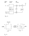
- a number of frequency channels k 1 to k n inclusive are modulated with different modulations from a message M.
- the frequency channels are mixed up to the carrier frequency f o and transmitted via amplifiers and circulators out through the antenna.
- Radar echoes from targets are captured by the antenna and pass the circulator and receiver shield. Thereafter, the received signal is mixed down to each respective band frequency from which modulations M 1 to M n inclusive are obtained from each respective channel.
- the radar transmitter may, for example, transmit on one frequency channel at a time and repeat the transmission on the same frequencies several times during the period the antenna scans over a radar target.
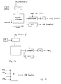
- Fig. 1 shows how the modulation M 1 from the frequency channel k 1 is fed to a correlator which correlates with the transmitted modulation.
- the resulting measurement value for each distance increment and angular increment is stored in order to be outputted for the same distance for angular analysis.
- the measurement values are fed successively into the correlator and are correlated with stored data obtained from the shape of the antenna lobe.
- the result is analysed in an analyser unit A 1 , where possible standardization and positional determination are carried out, whereafter the result is printed out, "Target 1 ".
- the modulation M 2 is fed in parallel from the frequency channel k 2 to a corresponding apparatus, and the result "Target 2" is obtained.
- Fig. 1c shows how the results "Target 1" and “Target 2" from analysis of the different transmitterfre- quencies are fed to the analyser unit B.
- the results for the same angle sector are compiled, and the result will be target width position.
- Target also includes a Q factor for determination of position, which depends upon the quantity of target interaction.
- Fig. 1d shows how target positions are stored together with their Q factor.
- targets are interlinked to target figures which, in their turn, can be compared with stored target figures for vessels etc.
- the result may, for example, be displayed on a screen where operators may select targets, continued monitoring or combat. Tracking and successive evaluation of one or more targets is carried out by a "target tracker" with the aid of the analyses described above.
- Fig. 2 shows uppermost, the correlator principle in which measurement values for the same radar frequency are successively inputted and correlated with stored information obtained from the lobe shape of the antenna.
- the figure shows (lowermost) how the correlator can be divided up into three subsectors which are each divided up into two parts. From each part, there is obtained a correlator result L 1 up to E 32 inclusive. Both difference and total for each respective subsector can be derived herefrom.
- These values may, according to the present invention, be employed for obtaining Q factors of target positions.
- the shape of the antenna lobe plays a major part in defining the angular position of a target.
- the flanks of the antenna lobe have valuable information on a target, since the measurement values of the target have a large and clearly defined derivative in these areas.
- the central portion of the antenna lobe is also valuable, since the measurement values of the target have their largest size here and may therefore conceivably dominate over other radar targets wh ich are located lower down on the flanks of the antenna lobe when the radar antenna points straight at the target in question.
- the information from the three different areas in the antenna lobe can be employed in alternative ways.
- a number of examples will be presented to illustrate this function.
- Values which describe the shape of the antenna lobe are stored in a correlator with the same angular steps as incoming measurement data.
- data on the shape of the antenna lobe has been obtained from direct measurements of the relevant antenna.
- Incoming measurement data is fed successively into the correlator and, when the pertinent target is centered, i.e. in maximum agreement with the lobe shape, the correlator gives a maximum value.
- target 1 and target 2 may be clearly separated in the correlator even though they lie close to one another in the angular direction. Parallel measurement on several frequencies aids in the separation.
- the target A 1 f 1 ( ⁇ o ) can then be obtained from A 2 ⁇ f 2 ( ⁇ ) h( ⁇ - ⁇ o ) where 0 is stepped by ⁇ , which is the angu- lar distance between the measurement values.
- ⁇ o is unknown
- a correlator is practical for obtaining the target and its position ⁇ o .
- the function h ( ⁇ ) is stored, and the measurement values are entered in sequence.
- the stored information is multiplied by the entered values and is sum totalled.
- correlation will be at maximum and the position of the target defined by this maximum. Forwide antenna lobes, the maximum may be experienced as flat and adjacent targets may interfere with the measurement.
- h ( ⁇ ) may be changed from an exact replica of the antenna lobe.
- h ( ⁇ ) may be res- caled and become narrower h ( ⁇ ) - h 1 (k ⁇ ). This entails that the side lobe level increases and k (scale factor) must be selected as a compromise between lobe width and side lobes.
- h 1 ( ⁇ ) as a function which, in the signal processing unit, can change the lobe shape of the receiver antenna.
- h 1 ( ⁇ ) may be formulated such that h 1 ( ⁇ ) includes the closest side lobes on either side within the original lobe shape of h ( ⁇ ).
- h ( ⁇ ) gives low side lobes
- h ( ⁇ ) can be employed in which the low side lobes are of interest
- h 1 ( ⁇ ) can be employed in those particular cases where separation of closely adjacent targets is given priority.
- Those values which are obtained in the extra correlators can therefore be retransformed, and, via the regular correlator, be subtracted from the correlator information the regular correlator.
- the target values in the extra correlators which are uncorrelated with the target position in the regular correlator give a slight contribution.
- targets which assume an intermediate position give contributions both in the regular correlator and in one of the extra correlators, and the interaction of these targets in the regular correlator can be reduced by transformation of the values obtained in the extra correlator so as to compensate for values in the regular correlator.
- the antenna lobe is divided into three sectors, each 0.5 0 3 in width.
- the centre section thus extends 0.25 0 3 in either direction.
- left and right flank portions follow one another symmetrically 0.5 ⁇ 3 .
- the measurement distances together amount to 0.5 0 3 .
- the 3 dB points of the antenna lobe define the lobe width ⁇ 3 , which implies that, if the same antenna is employed for both transmission and reception, a signal received in the 3 dB point will be 6 dB lower than a signal from the lobe centre of the antenna. (This implies that a two-wave antenna has a narrower 3 dB lobe width than a corresponding single-wave antenna and thus also potential for better angular resolution.)
- Each one of the three above-mentioned antenna sectors are divided up into two subsectors and subsequent signal processing is effected in the different sectors.
- the denominator in P Fv and P FH can alternatively be changed to ⁇ M .
- the signal processing may be illustrated most simply as follows.
- the measurement values from the receiver of the radar are sorted with each frequency independently, and are stored in a series corresponding to the angle width 1.5 ⁇ ⁇ 3 .
- the oldest is rejected. If a punctiform target has just been passed by the antenna lobe so that the last measurement value is 0.75 . 0 3 from lobe centre, it thus applies that the accumulated, stored series of measurement values covers positions of the target from the one flank sector, across the central sector, to the other flank sector, and the centremost measurement value then corresponds to the position where the target is in the centre of the lobe.
- target number 2 has its largest echo signals displaced to the one flank sector of the measurement series. In the central sector of the measurement series, target number 2 has those echo signals which correspond to the flank of the antenna lobe.
- Target number 2 interacts with target number 1 in the different sectors as follows.
- Centre sector if target number 2 is small and also has its centre value reduced 6 dB (flank value), target number 2 influences the value ⁇ M relatively slightly as compared with how target number 2 influences the value 8 M .
- Target number 2 presents a powerful derivate in the centre sector. This implies that PM will be smaller and that P M will have its maximum value with the measurement series somewhat displaced from the centre value of target number 1.
- target number 2 has its signal maximum in the left flank sector of the measurement series, we will then have target number 2 centered in this sector and a relatively slight contribution to ⁇ FV . If target 2 is as large as target 1, ⁇ FV will be dominated by target 2 and P FV is greatly reduced. If instead P FV normed with ⁇ M , P FV will be greater, and if P M is of reasonable magnitude, this may be better information on target interference.
- Target number 2 has very low signal effect in the right flank sector of the measurement series (centre lies in the left flank) and will thus have little effect on PFH.
- P M indicates that there is a target within a corresponding angular sector. If target number 2 is small compared with target number 1, P M will be large and the angular sector will be narrow.
- P FV , P FH and P M may be utilized in several ways.
- a single value of P FV , P FH or P M which is higher than a threshold value T 1 is a correspondingly reliable indication of a target in the relevant position.
- P M (with the relevant subsidiary condition that P M is larger than T 2 ), which is larger than a threshold T 3 constitutes a correspondingly reliable target position.
- the threshold T 3 may be selected to be lower than T 1 and a corresponding threshold for the product P FV - P FH .
- P M may be selected to be lower than T 3 for a certain reliability in target position.
- phase of the measurement values also includes information on the radar targets.
- phase information and several measurement values on the same frequency are required. Targets which move at constant speed change the phase of the radar reflection at constant speed, which gives rise to a doppler shift of the frequency of the received signal in relation to the transmitted radar frequency.
- the measurement values are divided up in an I and an O channel, and the correlators are fed with associated coefficients, corresponding to a given doppler band.
- Either a number of fixed correlators can be employed or, for example, an FFT (Fast Fourier Transform) can be effected for filtering targets to each respective doppler bin.
- FFT Fast Fourier Transform
- correlators can be given corresponding coefficients and thereby separate targets via correlation operation.
- Fixed correlators can be adapted to a number of typical or interesting speed sectors. For example, a low speed sector of about zero speed may be interesting in order to detect land targets or slowly moving targets. Another interesting sector is wind speed, since strips, small water droplets from water bursts, etc., can be caught up in this doppler bin.
- Some correlators can be allocated to interesting vessel speeds.
- phase values On division of a correlator into several subsectors and when phase information is included in the values from each respective subsector, it is necessary, on operation of the measurement values from different subsectors, that the phase values be dependent upon a common point of departure. This may, for example, be the centre point of the correlator or the interface between two affected subsectors.
- One method of employing phase information concerning the targets without explicit compensation for the doppler phase of the targets is obtained when the symmetry in the lobe shape is utilized. Pairwise multiplication of symmetric measurement values on either side of the correlator centre gives products without doppler phase and with target phase related to target values in the centre point.
- the range and angular information constitute basic information for a reliable resolution of target and determination of position.
- a target depiction (or target map) may be obtained in which the surface is defined by angle and range segments and a third dimension (altitude includes information on target probability in the relevant position).
- different colour shades may be employed to mark increasing target probability. It is also possible to identify, from the target depiction, associated resolution segments which may form target figures. Particularly interesting target figures such as vessels, for example, may be scanned and analysed. Such a target depiction may be employed for selecting, for example, particularly important targets for combatting.
- one of the previously mentioned methods affords an improved angular resolution.
- the water eruption or splash normally has a different doppler speed than the vessel target itself.
- the water On splash, the water has a spread of different radial speeds about the zero speed -water sprays at great vertical speed.
- the finest water droplets may float for some time in the air before falling down (several seconds) and will then have a radial velocity component which corresponds to the wind speed.
- Doppler speed may be a crucial basis for target sorting and target depiction according to the above description may be effected for a plurality of doppler segments.
- the lobe shape of the antenna plays a major role in the ability of the radar to perform angular resolution of targets. Different methods have been described above for correlating measurement data with information obtained from the lobe form.
- the lobe shape of the antenna may be obtained by careful measurements, possibly on several frequencies, and data may be stored in the radar. Modifications in signal processing of the lobe shape function may also be tested against actual targets, and suitable functions for artificially making the lobe narrower, and the angular resolution may better be evaluated and stored in the radar.
- the lobe shape may also be described and approximated using key terms from a Fourier series.
- Antenna lobes are normally of a form which is associated to some power of a cosine function, e.g. COS 2 or cos 4 .
- measurement data may be selected for analysis in the so-called frequency plane instead of the in the time plan. This method is well known within filter technology.
Landscapes
- Engineering & Computer Science (AREA)
- Radar, Positioning & Navigation (AREA)
- Remote Sensing (AREA)
- Computer Networks & Wireless Communication (AREA)
- Physics & Mathematics (AREA)
- General Physics & Mathematics (AREA)
- Radar Systems Or Details Thereof (AREA)
Applications Claiming Priority (2)
| Application Number | Priority Date | Filing Date | Title |
|---|---|---|---|
| SE9002967A SE9002967L (sv) | 1990-09-18 | 1990-09-18 | Radar |
| SE9002967 | 1990-09-18 |
Publications (2)
| Publication Number | Publication Date |
|---|---|
| EP0477155A2 true EP0477155A2 (de) | 1992-03-25 |
| EP0477155A3 EP0477155A3 (en) | 1993-06-09 |
Family
ID=20380388
Family Applications (1)
| Application Number | Title | Priority Date | Filing Date |
|---|---|---|---|
| EP19910850212 Withdrawn EP0477155A3 (en) | 1990-09-18 | 1991-09-04 | Radar means |
Country Status (4)
| Country | Link |
|---|---|
| EP (1) | EP0477155A3 (de) |
| FI (1) | FI914365L (de) |
| NO (1) | NO913664L (de) |
| SE (1) | SE9002967L (de) |
Cited By (6)
| Publication number | Priority date | Publication date | Assignee | Title |
|---|---|---|---|---|
| US6410149B1 (en) | 1998-08-27 | 2002-06-25 | Alliedsignal Inc. | Silane-based nanoporous silica thin films and precursors for making same |
| WO2007057475A3 (en) * | 2005-11-21 | 2007-08-02 | Plextek Ltd | Improvements to doppler radar systems |
| WO2008071167A3 (de) * | 2006-12-09 | 2008-10-16 | Adc Automotive Dist Control | Bestimmung der position eines objekts mit einem sensor |
| US7737886B2 (en) | 2005-11-21 | 2010-06-15 | Plextek Limited | Doppler radar systems |
| DE102024100605A1 (de) | 2024-01-10 | 2025-07-10 | Valeo Schalter Und Sensoren Gmbh | Verfahren zum Ermitteln einer Winkelinformation mittels eines Radargeräts für ein Kraftfahrzeug |
| EP3767325B1 (de) * | 2019-07-19 | 2026-01-07 | Aptiv Technologies AG | Verfahren und systeme zur verarbeitung von radarreflektionen |
Family Cites Families (1)
| Publication number | Priority date | Publication date | Assignee | Title |
|---|---|---|---|---|
| IT1206287B (it) * | 1987-05-26 | 1989-04-14 | Selenia Ind Elettroniche | La detezione e il riconoscimento di radar con agilita' di frequenza da bersagli di traccia multipla impulso a impulso, utilizzato per |
-
1990
- 1990-09-18 SE SE9002967A patent/SE9002967L/ not_active Application Discontinuation
-
1991
- 1991-09-04 EP EP19910850212 patent/EP0477155A3/en not_active Withdrawn
- 1991-09-17 FI FI914365A patent/FI914365L/fi not_active Application Discontinuation
- 1991-09-17 NO NO91913664A patent/NO913664L/no unknown
Cited By (9)
| Publication number | Priority date | Publication date | Assignee | Title |
|---|---|---|---|---|
| US6410149B1 (en) | 1998-08-27 | 2002-06-25 | Alliedsignal Inc. | Silane-based nanoporous silica thin films and precursors for making same |
| WO2007057475A3 (en) * | 2005-11-21 | 2007-08-02 | Plextek Ltd | Improvements to doppler radar systems |
| US7737886B2 (en) | 2005-11-21 | 2010-06-15 | Plextek Limited | Doppler radar systems |
| US7956799B2 (en) * | 2005-11-21 | 2011-06-07 | Plextek Limited | Frequency scanning radar system |
| WO2008071167A3 (de) * | 2006-12-09 | 2008-10-16 | Adc Automotive Dist Control | Bestimmung der position eines objekts mit einem sensor |
| DE112007001724B4 (de) | 2006-12-09 | 2022-02-10 | Adc Automotive Distance Control Systems Gmbh | Bestimmung der Position eines Objekts mit einem Sensor |
| EP3767325B1 (de) * | 2019-07-19 | 2026-01-07 | Aptiv Technologies AG | Verfahren und systeme zur verarbeitung von radarreflektionen |
| DE102024100605A1 (de) | 2024-01-10 | 2025-07-10 | Valeo Schalter Und Sensoren Gmbh | Verfahren zum Ermitteln einer Winkelinformation mittels eines Radargeräts für ein Kraftfahrzeug |
| WO2025149615A1 (de) | 2024-01-10 | 2025-07-17 | Valeo Schalter Und Sensoren Gmbh | Verfahren zum ermitteln einer winkelinformation mittels eines radargeräts für ein kraftfahrzeug |
Also Published As
| Publication number | Publication date |
|---|---|
| NO913664D0 (no) | 1991-09-17 |
| FI914365A7 (fi) | 1992-03-19 |
| SE9002967D0 (sv) | 1990-09-18 |
| SE9002967L (sv) | 1992-03-19 |
| FI914365A0 (fi) | 1991-09-17 |
| EP0477155A3 (en) | 1993-06-09 |
| NO913664L (no) | 1992-03-19 |
| FI914365L (fi) | 1992-03-19 |
Similar Documents
| Publication | Publication Date | Title |
|---|---|---|
| Adamy | EW 102: a second course in electronic warfare | |
| US5977905A (en) | Target detection method and device for wideband unambiguous pulse Doppler radar | |
| Haykin et al. | Maximum-entropy spectral analysis of radar clutter | |
| CN103210319B (zh) | 雷达系统 | |
| EP0093603A1 (de) | Feuerleiteinrichtung für bewegliche Ziele | |
| DE102011012680B3 (de) | Verfahren zur Erfassung der Flugbahn von Projektilen | |
| US20060071847A1 (en) | Method and apparatus for correcting velocity-induced range estimate phase errors in a two-tone monopulse CW radar | |
| JP2011247902A (ja) | 速度が曖昧な物標の非コヒーレント積分のための技法 | |
| RU2352958C1 (ru) | Лазерный когерентный локатор | |
| EP0704713A1 (de) | Entdecken eines Störers, welcher über seine vom Boden reflektierten Signale stört, mittels Bodenstörecho-Ermittlung | |
| US20150109163A1 (en) | Target Detection System and Method | |
| US5115246A (en) | Radar target locating and tracking apparatus using a dual-interleaved pulse train radar waveform | |
| US6680687B2 (en) | Method to determine the azimuth of a target by means of a radar, especially of the ASR type | |
| US3992710A (en) | Target tracker having target recognition means | |
| CN113030878A (zh) | 对空时自适应处理的非均匀间歇采样随机转发干扰方法 | |
| CN114371452B (zh) | 对合成孔径雷达运动补偿的干扰方法及干扰装置 | |
| US12164056B2 (en) | Context based target detection | |
| US10845475B2 (en) | Method of measuring azimuth of radar target | |
| RU2150714C1 (ru) | Способ измерения поперечных размеров радиолокационных объектов рлс в реальном масштабе времени | |
| US6816109B1 (en) | Method for automatic association of moving target indications from entities traveling along known route | |
| RU2084920C1 (ru) | Способ селекции движущихся наземных целей | |
| EP0477156A2 (de) | Radargerät | |
| Li et al. | Ship focusing and positioning based on 2-D ambiguity resolving for single-channel SAR mounted on high-speed maneuvering platforms with small aperture | |
| Sharma | The influence of target acceleration on dual-channel SAR-GMTI (synthetic aperture radar ground moving target indication) data | |
| CN114114266B (zh) | 对合成孔径雷达的侦测方法及装置 |
Legal Events
| Date | Code | Title | Description |
|---|---|---|---|
| PUAI | Public reference made under article 153(3) epc to a published international application that has entered the european phase |
Free format text: ORIGINAL CODE: 0009012 |
|
| AK | Designated contracting states |
Kind code of ref document: A2 Designated state(s): AT BE CH DE DK ES FR GB GR IT LI LU NL SE |
|
| PUAL | Search report despatched |
Free format text: ORIGINAL CODE: 0009013 |
|
| AK | Designated contracting states |
Kind code of ref document: A3 Designated state(s): AT BE CH DE DK ES FR GB GR IT LI LU NL SE |
|
| STAA | Information on the status of an ep patent application or granted ep patent |
Free format text: STATUS: THE APPLICATION IS DEEMED TO BE WITHDRAWN |
|
| 18D | Application deemed to be withdrawn |
Effective date: 19931210 |