EP0477399A1 - Dispositif pour démagnétiser un tube d'image - Google Patents
Dispositif pour démagnétiser un tube d'image Download PDFInfo
- Publication number
- EP0477399A1 EP0477399A1 EP90118415A EP90118415A EP0477399A1 EP 0477399 A1 EP0477399 A1 EP 0477399A1 EP 90118415 A EP90118415 A EP 90118415A EP 90118415 A EP90118415 A EP 90118415A EP 0477399 A1 EP0477399 A1 EP 0477399A1
- Authority
- EP
- European Patent Office
- Prior art keywords
- demagnetizing
- picture tube
- switching element
- semiconductor switching
- controllable semiconductor
- Prior art date
- Legal status (The legal status is an assumption and is not a legal conclusion. Google has not performed a legal analysis and makes no representation as to the accuracy of the status listed.)
- Withdrawn
Links
- 238000004804 winding Methods 0.000 claims abstract description 24
- 239000004065 semiconductor Substances 0.000 claims abstract description 20
- 230000005347 demagnetization Effects 0.000 claims description 23
- 230000003287 optical effect Effects 0.000 claims description 2
- XEEYBQQBJWHFJM-UHFFFAOYSA-N Iron Chemical compound [Fe] XEEYBQQBJWHFJM-UHFFFAOYSA-N 0.000 description 5
- 239000003990 capacitor Substances 0.000 description 2
- 229910052742 iron Inorganic materials 0.000 description 2
- 230000007423 decrease Effects 0.000 description 1
- 230000003111 delayed effect Effects 0.000 description 1
- 230000001419 dependent effect Effects 0.000 description 1
- 238000011161 development Methods 0.000 description 1
- 230000018109 developmental process Effects 0.000 description 1
- 238000010894 electron beam technology Methods 0.000 description 1
- 238000010438 heat treatment Methods 0.000 description 1
- 238000000034 method Methods 0.000 description 1
Images

Classifications
-
- H—ELECTRICITY
- H04—ELECTRIC COMMUNICATION TECHNIQUE
- H04N—PICTORIAL COMMUNICATION, e.g. TELEVISION
- H04N9/00—Details of colour television systems
- H04N9/12—Picture reproducers
- H04N9/16—Picture reproducers using cathode ray tubes
- H04N9/29—Picture reproducers using cathode ray tubes using demagnetisation or compensation of external magnetic fields
Definitions
- the invention relates to a device for demagnetizing a picture tube with the features of the preamble of claim 1.
- a second PTC thermistor is provided in close thermal contact with the above-mentioned PTC thermistor, which is parallel to the AC mains voltage. This second PTC thermistor also heats up when the mains AC voltage is switched on, thereby heating the first PTC thermistor so that only an extremely small current can flow through the demagnetization winding.
- Such a demagnetization circuit for color picture tubes is used today in almost every color television set.
- the problem with this known demagnetization circuit is the fact that the PTC thermistor and the demagnetization winding are constantly connected to the mains AC voltage when the device is switched on and thus continuously consume an output of approximately 3 watts in order to remain hot and thus high-impedance. This is particularly annoying in the stand-by mode of television sets, since the power switch is closed in this state. The power consumption in the stand-by mode of a television set cannot therefore be arbitrarily reduced, contrary to the demand for the lowest possible power consumption.
- Another disadvantage of this known demagnetization circuit is the fact that the demagnetization is only effective after the mains switch of the device has been switched on. A decaying alternating current is only sent through the demagnetization winding when the device is switched on. After the PTC thermistor has heated up, it is no longer possible to demagnetize the picture tube without having to press the power switch. This is particularly problematic when the television is in stand-by mode and an interference field magnetizes the iron shield arranged on the piston of the picture tube. So z. B. when switching on the TV using a remote control from standby mode, demagnetization of the picture tube is no longer possible.
- the invention has for its object to provide a device for demagnetizing a picture tube, which is characterized by a reduced power consumption and can also be activated when the television set is switched on from stand-by mode.
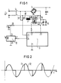
- the light-controllable triac 2 is driven in pulses by light that is emitted by a light-emitting diode 40, as a result of which the triac 2 can ignite. Provided that the switching device 4 is closed, this triac 2 switches the current I through the demagnetization winding 1.
- an actuation pulse for the triac 2 is emitted to an output terminal 22 of the control device 3 with every half-wave of the mains AC voltage U after a zero crossing. This happens more and more delayed, until after about 500 msec, ie at a 50 Hertz mains frequency after 50 half-waves, the process is finished. In this way, a phase control is achieved, as is shown in principle in FIG. 2.
- the AC line voltage is denoted by U and the voltage drop across the demagnetizing winding 1 is denoted by U E.
- U E the voltage drop across the demagnetizing winding 1
- the control device 3 receives information on the zero crossings of the AC line voltage U at an input terminal 23.
- the input terminal 23 is connected to the resistors 31, 30 with the highest possible resistance and the switching device 4 to the Input terminals 5 and 6 of the AC line voltage source U switched.
- the voltage supply for the control device 3 takes place via the terminals 20 and 21, the terminal 21 being at reference potential and the terminal 20 being connected to the input terminal 6 via a resistor and the switching device 4.
- the terminal 20 of the control device 3 is connected to the cathode of a zener diode 15, the anode of which is at reference potential.
- a capacitor 17 is connected in parallel with this zener diode 15.
- the demagnetizing winding 1 is supplied with a decaying alternating current, immediately after the switching device 4 is switched on. This is always the case when the television set is brought from the off state into the on state.
- the control device 3 has a further input 24, which is connected to the output 27 of a remote control receiver, for. B. an infrared preamplifier with a downstream demodulator.
- This remote control receiver 10 is supplied with voltage via terminals 25 and 26, z. B. the terminal 26 is connected to reference potential and the terminal 25 via an RC element 28, 29 to the cathode of the Zener diode 15.
- the control device 3 As soon as the reception of a switch-on command of a remote control is detected in the remote control receiver 10, the control device 3 generates at its output 22 a signal for driving the light-emitting diode 40 in a pulsed manner, as explained above, whereby the light-sensitive triac 2 can be ignited again in such a way that a phase control of the mains AC voltage is ensured is.
- the television set it is then no longer necessary, as in the prior art, to switch the television set off via the switching device 4 in order to switch it on again. Rather, with the device according to the invention for demagnetizing the picture tube, the television set is demagnetized even after being switched on from standby mode.
- control device 3 is switched to reference potential, as shown by way of example in FIG. 1, a potential-free control of the controllable semiconductor switching element 2 is necessary. As shown in FIG. 1, this can be done by an optical control but also by a control familiar to the person skilled in the art by means of an ignition transformer. As a controllable semiconductor switching element would, for. B. also two antiparallel connected thyristors or transistors can be used.
- FIG 3 shows a second exemplary embodiment of a device according to the invention for demagnetizing a picture tube with a two-part demagnetizing winding 1 a, 1 b, the center tap of which is at reference potential.
- a floating control of the controllable semiconductor switching element 2 is no longer necessary.
- FIG 3 shows a device for demagnetizing a picture tube, which is characterized in that the demagnetizing winding has a center tap and two outer connections, that the outer connections are each connected to a cathode connection of a diode, the anode connections of which are parallel to the terminals via the switching device lie, and that the controllable semiconductor switching element is connected with its load path between the center tap and a reference potential.
Landscapes
- Engineering & Computer Science (AREA)
- Multimedia (AREA)
- Signal Processing (AREA)
- Video Image Reproduction Devices For Color Tv Systems (AREA)
Priority Applications (1)
| Application Number | Priority Date | Filing Date | Title |
|---|---|---|---|
| EP90118415A EP0477399A1 (fr) | 1990-09-25 | 1990-09-25 | Dispositif pour démagnétiser un tube d'image |
Applications Claiming Priority (1)
| Application Number | Priority Date | Filing Date | Title |
|---|---|---|---|
| EP90118415A EP0477399A1 (fr) | 1990-09-25 | 1990-09-25 | Dispositif pour démagnétiser un tube d'image |
Publications (1)
| Publication Number | Publication Date |
|---|---|
| EP0477399A1 true EP0477399A1 (fr) | 1992-04-01 |
Family
ID=8204512
Family Applications (1)
| Application Number | Title | Priority Date | Filing Date |
|---|---|---|---|
| EP90118415A Withdrawn EP0477399A1 (fr) | 1990-09-25 | 1990-09-25 | Dispositif pour démagnétiser un tube d'image |
Country Status (1)
| Country | Link |
|---|---|
| EP (1) | EP0477399A1 (fr) |
Cited By (3)
| Publication number | Priority date | Publication date | Assignee | Title |
|---|---|---|---|---|
| DE4237634A1 (de) * | 1992-11-07 | 1994-05-11 | Nokia Deutschland Gmbh | Videoempfangsgerät mit einem Schaltnetzteil |
| WO1995007006A1 (fr) * | 1993-08-31 | 1995-03-09 | Instrumentacion Electronica Promax, S.A. | Circuit de demagnetisation sequentielle |
| WO1998059499A1 (fr) * | 1997-06-25 | 1998-12-30 | Koninklijke Philips Electronics N.V. | Demagnetisation |
Citations (2)
| Publication number | Priority date | Publication date | Assignee | Title |
|---|---|---|---|---|
| US4262232A (en) * | 1979-11-30 | 1981-04-14 | Rca Corp. | Color television degaussing circuit |
| DE3831306A1 (de) * | 1988-09-15 | 1990-03-29 | Vogt Electronic Ag | Entmagnetisierungsschaltung |
-
1990
- 1990-09-25 EP EP90118415A patent/EP0477399A1/fr not_active Withdrawn
Patent Citations (2)
| Publication number | Priority date | Publication date | Assignee | Title |
|---|---|---|---|---|
| US4262232A (en) * | 1979-11-30 | 1981-04-14 | Rca Corp. | Color television degaussing circuit |
| DE3831306A1 (de) * | 1988-09-15 | 1990-03-29 | Vogt Electronic Ag | Entmagnetisierungsschaltung |
Non-Patent Citations (2)
| Title |
|---|
| PATENT ABSTRACTS OF JAPAN, Band 1, Nr. 146 (E-068), 26. November 1977; & JP-A-52 084 919 (SANYO DENKI K.K.) 14-07-1977 * |
| PATENT ABSTRACTS OF JAPAN, Band 3, Nr. 78 (E-121), 5. Juli 1979; & JP-A-54 056 325 (MATSUSHITA DENKI SANGYO K.K.) 07-05-1979 * |
Cited By (6)
| Publication number | Priority date | Publication date | Assignee | Title |
|---|---|---|---|---|
| DE4237634A1 (de) * | 1992-11-07 | 1994-05-11 | Nokia Deutschland Gmbh | Videoempfangsgerät mit einem Schaltnetzteil |
| EP0598267A3 (en) * | 1992-11-07 | 1994-06-15 | Nokia Technology Gmbh | Television receiver with a switching power supply. |
| WO1995007006A1 (fr) * | 1993-08-31 | 1995-03-09 | Instrumentacion Electronica Promax, S.A. | Circuit de demagnetisation sequentielle |
| ES2078860A2 (es) * | 1993-08-31 | 1995-12-16 | Instrumentacion Electronica Pr | Circuito de desmagnetizacion secuencial. |
| WO1998059499A1 (fr) * | 1997-06-25 | 1998-12-30 | Koninklijke Philips Electronics N.V. | Demagnetisation |
| US5940261A (en) * | 1997-06-25 | 1999-08-17 | U.S. Philips Corporation | Circuit and method independent of frequency and voltage deviations of supply voltage, and display apparatus incorporating same circuit |
Similar Documents
| Publication | Publication Date | Title |
|---|---|---|
| DE68911400T2 (de) | Geschaltete Speisespannungsschaltung. | |
| DE1804429C3 (de) | Gleichstromübertrager mit variablem Übersetzungsverhältnis | |
| DE3118816C2 (de) | Entmagnetisierungsschaltung für einen Farbfernseher | |
| EP0477399A1 (fr) | Dispositif pour démagnétiser un tube d'image | |
| DE10162048A1 (de) | Schaltungsanordnung mit Powerfaktorkorrektur, sowie entsprechendes Gerät | |
| DE3044917C2 (de) | Entmagnetisierungsschaltung für einen Farbfernsehempfänger | |
| EP0492314B1 (fr) | Circuit de démagnétisation pour le tube d'image dans un récepteur de télévision | |
| DE2437633C3 (de) | Spannungsregelschaltung für eine Ablenkschaltung | |
| EP0354321B1 (fr) | Circuit pour la désaimantation du masque d'ombre dans un tube image couleur | |
| DE19855457A1 (de) | Entmagnetisierungsschaltung | |
| DE3418076C2 (de) | Schaltungsanordnung zur automatischen Entmagnetisierung der Bildröhre in einem Farbfernsehempfänger | |
| DE3701588A1 (de) | Schalteinrichtung fuer eine induktive last | |
| DE2835611A1 (de) | Schaltung zur entmagnetisierung der bildroehre in einem farbfernsehempfaenger | |
| EP0598267A2 (fr) | Récepteur de télévision muni d'une alimentation à découpage | |
| DE69315640T2 (de) | Verzögerungsmittel in einer Anlaufschaltung eines Vorschaltgerätes | |
| DE1811526A1 (de) | Regelschaltung fuer die Energieversorgung eines elektrischen Verbrauchers | |
| DE1275104B (de) | Selbstschwingende Horizontalablenkschaltung, insbesondere fuer Fernsehempfaenger | |
| DE2315497A1 (de) | Helligkeitssteuerschaltung fuer gasentladungslampen | |
| EP0055995A1 (fr) | Disposition de circuit d'allumage et fonctionnement d'une lampe de décharge à basse pression à partir d'une source de courant continu | |
| EP0471228A1 (fr) | Starter pour lampes fluorescentes | |
| DE2835613A1 (de) | Schaltung zur entmagnetisierung der bildroehre in einem farbfernsehempfaenger | |
| EP0391032B1 (fr) | Circuit de désaimantation d'un tube image dans un dispositif d'affichage vidéo | |
| DE10014383A1 (de) | Entmagnetisierungsschaltung | |
| DE3040365A1 (de) | Steuerschaltung zum schnellen schalten eines steuerbaren halbleiters | |
| DE1811048A1 (de) | Hochfrequenz-Stromversorgungsschaltung |
Legal Events
| Date | Code | Title | Description |
|---|---|---|---|
| PUAI | Public reference made under article 153(3) epc to a published international application that has entered the european phase |
Free format text: ORIGINAL CODE: 0009012 |
|
| 17P | Request for examination filed |
Effective date: 19901205 |
|
| AK | Designated contracting states |
Kind code of ref document: A1 Designated state(s): AT BE CH DE DK ES FR GB GR IT LI LU NL SE |
|
| RBV | Designated contracting states (corrected) |
Designated state(s): DE ES FR GB IT |
|
| STAA | Information on the status of an ep patent application or granted ep patent |
Free format text: STATUS: THE APPLICATION IS DEEMED TO BE WITHDRAWN |
|
| 18D | Application deemed to be withdrawn |
Effective date: 19940401 |