EP0477435A1 - Verfahren zur Herstellung einer optischen Faser, optische Faser auf Silikatbasis und auf Quarzbasis - Google Patents
Verfahren zur Herstellung einer optischen Faser, optische Faser auf Silikatbasis und auf Quarzbasis Download PDFInfo
- Publication number
- EP0477435A1 EP0477435A1 EP90125440A EP90125440A EP0477435A1 EP 0477435 A1 EP0477435 A1 EP 0477435A1 EP 90125440 A EP90125440 A EP 90125440A EP 90125440 A EP90125440 A EP 90125440A EP 0477435 A1 EP0477435 A1 EP 0477435A1
- Authority
- EP
- European Patent Office
- Prior art keywords
- hydrogen
- fiber
- gas
- furnace
- optical fiber
- Prior art date
- Legal status (The legal status is an assumption and is not a legal conclusion. Google has not performed a legal analysis and makes no representation as to the accuracy of the status listed.)
- Withdrawn
Links
- 239000013307 optical fiber Substances 0.000 title claims abstract description 43
- VYPSYNLAJGMNEJ-UHFFFAOYSA-N Silicium dioxide Chemical compound O=[Si]=O VYPSYNLAJGMNEJ-UHFFFAOYSA-N 0.000 title claims description 20
- 239000000377 silicon dioxide Substances 0.000 title claims description 9
- 238000004519 manufacturing process Methods 0.000 title claims description 8
- BPQQTUXANYXVAA-UHFFFAOYSA-N Orthosilicate Chemical compound [O-][Si]([O-])([O-])[O-] BPQQTUXANYXVAA-UHFFFAOYSA-N 0.000 title claims description 5
- 239000001257 hydrogen Substances 0.000 claims abstract description 99
- 229910052739 hydrogen Inorganic materials 0.000 claims abstract description 99
- 239000000835 fiber Substances 0.000 claims abstract description 87
- UFHFLCQGNIYNRP-UHFFFAOYSA-N Hydrogen Chemical compound [H][H] UFHFLCQGNIYNRP-UHFFFAOYSA-N 0.000 claims abstract description 84
- 239000007789 gas Substances 0.000 claims abstract description 48
- 238000012681 fiber drawing Methods 0.000 claims abstract description 4
- 238000000034 method Methods 0.000 claims description 26
- 150000002431 hydrogen Chemical class 0.000 claims description 15
- 238000005253 cladding Methods 0.000 claims description 14
- 239000011521 glass Substances 0.000 claims description 13
- 239000001307 helium Substances 0.000 claims description 13
- 229910052734 helium Inorganic materials 0.000 claims description 13
- SWQJXJOGLNCZEY-UHFFFAOYSA-N helium atom Chemical compound [He] SWQJXJOGLNCZEY-UHFFFAOYSA-N 0.000 claims description 13
- 239000000203 mixture Substances 0.000 claims description 13
- QVGXLLKOCUKJST-UHFFFAOYSA-N atomic oxygen Chemical compound [O] QVGXLLKOCUKJST-UHFFFAOYSA-N 0.000 claims description 12
- 239000001301 oxygen Substances 0.000 claims description 12
- 229910052760 oxygen Inorganic materials 0.000 claims description 12
- XKRFYHLGVUSROY-UHFFFAOYSA-N Argon Chemical compound [Ar] XKRFYHLGVUSROY-UHFFFAOYSA-N 0.000 claims description 6
- 238000010438 heat treatment Methods 0.000 claims description 5
- 239000000463 material Substances 0.000 claims description 4
- 229910052786 argon Inorganic materials 0.000 claims description 3
- 239000002019 doping agent Substances 0.000 claims description 2
- 239000003570 air Substances 0.000 claims 3
- 239000000470 constituent Substances 0.000 claims 1
- 230000007547 defect Effects 0.000 abstract description 13
- 230000001052 transient effect Effects 0.000 description 12
- 238000000576 coating method Methods 0.000 description 11
- 239000011248 coating agent Substances 0.000 description 8
- 239000002245 particle Substances 0.000 description 8
- 238000010521 absorption reaction Methods 0.000 description 7
- 238000000151 deposition Methods 0.000 description 7
- 230000008021 deposition Effects 0.000 description 7
- 238000009792 diffusion process Methods 0.000 description 7
- 230000003247 decreasing effect Effects 0.000 description 6
- 230000000694 effects Effects 0.000 description 6
- YBMRDBCBODYGJE-UHFFFAOYSA-N germanium dioxide Chemical compound O=[Ge]=O YBMRDBCBODYGJE-UHFFFAOYSA-N 0.000 description 6
- 239000011261 inert gas Substances 0.000 description 6
- 229910003910 SiCl4 Inorganic materials 0.000 description 5
- FDNAPBUWERUEDA-UHFFFAOYSA-N silicon tetrachloride Chemical compound Cl[Si](Cl)(Cl)Cl FDNAPBUWERUEDA-UHFFFAOYSA-N 0.000 description 5
- 229910006113 GeCl4 Inorganic materials 0.000 description 4
- 230000015572 biosynthetic process Effects 0.000 description 4
- 150000001875 compounds Chemical class 0.000 description 4
- 230000003287 optical effect Effects 0.000 description 4
- 239000000376 reactant Substances 0.000 description 4
- 235000012239 silicon dioxide Nutrition 0.000 description 4
- IEXRMSFAVATTJX-UHFFFAOYSA-N tetrachlorogermane Chemical compound Cl[Ge](Cl)(Cl)Cl IEXRMSFAVATTJX-UHFFFAOYSA-N 0.000 description 4
- 230000007246 mechanism Effects 0.000 description 3
- 230000001902 propagating effect Effects 0.000 description 3
- 230000003595 spectral effect Effects 0.000 description 3
- XLYOFNOQVPJJNP-UHFFFAOYSA-N water Substances O XLYOFNOQVPJJNP-UHFFFAOYSA-N 0.000 description 3
- IJGRMHOSHXDMSA-UHFFFAOYSA-N Atomic nitrogen Chemical compound N#N IJGRMHOSHXDMSA-UHFFFAOYSA-N 0.000 description 2
- OKTJSMMVPCPJKN-UHFFFAOYSA-N Carbon Chemical compound [C] OKTJSMMVPCPJKN-UHFFFAOYSA-N 0.000 description 2
- ZAMOUSCENKQFHK-UHFFFAOYSA-N Chlorine atom Chemical compound [Cl] ZAMOUSCENKQFHK-UHFFFAOYSA-N 0.000 description 2
- MCMNRKCIXSYSNV-UHFFFAOYSA-N Zirconium dioxide Chemical compound O=[Zr]=O MCMNRKCIXSYSNV-UHFFFAOYSA-N 0.000 description 2
- 230000032683 aging Effects 0.000 description 2
- 229910052799 carbon Inorganic materials 0.000 description 2
- 238000006243 chemical reaction Methods 0.000 description 2
- 239000000460 chlorine Substances 0.000 description 2
- 229910052801 chlorine Inorganic materials 0.000 description 2
- 229910052681 coesite Inorganic materials 0.000 description 2
- 238000007596 consolidation process Methods 0.000 description 2
- 229910052906 cristobalite Inorganic materials 0.000 description 2
- 230000007423 decrease Effects 0.000 description 2
- 230000003111 delayed effect Effects 0.000 description 2
- 238000013461 design Methods 0.000 description 2
- 239000007788 liquid Substances 0.000 description 2
- 230000003647 oxidation Effects 0.000 description 2
- 238000007254 oxidation reaction Methods 0.000 description 2
- 239000005373 porous glass Substances 0.000 description 2
- 230000002441 reversible effect Effects 0.000 description 2
- 229910052682 stishovite Inorganic materials 0.000 description 2
- 229910052905 tridymite Inorganic materials 0.000 description 2
- MYMOFIZGZYHOMD-UHFFFAOYSA-N Dioxygen Chemical compound O=O MYMOFIZGZYHOMD-UHFFFAOYSA-N 0.000 description 1
- 101100424636 Saccharomyces cerevisiae (strain ATCC 204508 / S288c) TUB3 gene Proteins 0.000 description 1
- 101150026222 TUBB3 gene Proteins 0.000 description 1
- HSFWRNGVRCDJHI-UHFFFAOYSA-N alpha-acetylene Natural products C#C HSFWRNGVRCDJHI-UHFFFAOYSA-N 0.000 description 1
- PNEYBMLMFCGWSK-UHFFFAOYSA-N aluminium oxide Inorganic materials [O-2].[O-2].[O-2].[Al+3].[Al+3] PNEYBMLMFCGWSK-UHFFFAOYSA-N 0.000 description 1
- 238000004458 analytical method Methods 0.000 description 1
- 238000005229 chemical vapour deposition Methods 0.000 description 1
- 238000004891 communication Methods 0.000 description 1
- 239000002131 composite material Substances 0.000 description 1
- 239000000356 contaminant Substances 0.000 description 1
- 238000010586 diagram Methods 0.000 description 1
- 239000006185 dispersion Substances 0.000 description 1
- 229920006240 drawn fiber Polymers 0.000 description 1
- 238000001035 drying Methods 0.000 description 1
- 238000005516 engineering process Methods 0.000 description 1
- 125000002534 ethynyl group Chemical group [H]C#C* 0.000 description 1
- 238000011010 flushing procedure Methods 0.000 description 1
- 239000011888 foil Substances 0.000 description 1
- 239000002737 fuel gas Substances 0.000 description 1
- 239000003365 glass fiber Substances 0.000 description 1
- 230000007062 hydrolysis Effects 0.000 description 1
- 238000006460 hydrolysis reaction Methods 0.000 description 1
- 238000009413 insulation Methods 0.000 description 1
- 230000003993 interaction Effects 0.000 description 1
- 238000005259 measurement Methods 0.000 description 1
- 238000012986 modification Methods 0.000 description 1
- 230000004048 modification Effects 0.000 description 1
- 229910052757 nitrogen Inorganic materials 0.000 description 1
- 238000012545 processing Methods 0.000 description 1
- 238000007789 sealing Methods 0.000 description 1
- 230000035945 sensitivity Effects 0.000 description 1
- 239000005368 silicate glass Substances 0.000 description 1
- 238000001228 spectrum Methods 0.000 description 1
- 230000035882 stress Effects 0.000 description 1
- 238000007740 vapor deposition Methods 0.000 description 1
Images

Classifications
-
- G—PHYSICS
- G02—OPTICS
- G02B—OPTICAL ELEMENTS, SYSTEMS OR APPARATUS
- G02B6/00—Light guides; Structural details of arrangements comprising light guides and other optical elements, e.g. couplings
- G02B6/02—Optical fibres with cladding with or without a coating
-
- C—CHEMISTRY; METALLURGY
- C03—GLASS; MINERAL OR SLAG WOOL
- C03B—MANUFACTURE, SHAPING, OR SUPPLEMENTARY PROCESSES
- C03B37/00—Manufacture or treatment of flakes, fibres, or filaments from softened glass, minerals, or slags
- C03B37/01—Manufacture of glass fibres or filaments
- C03B37/02—Manufacture of glass fibres or filaments by drawing or extruding, e.g. direct drawing of molten glass from nozzles; Cooling fins therefor
- C03B37/025—Manufacture of glass fibres or filaments by drawing or extruding, e.g. direct drawing of molten glass from nozzles; Cooling fins therefor from reheated softened tubes, rods, fibres or filaments, e.g. drawing fibres from preforms
- C03B37/029—Furnaces therefor
-
- C—CHEMISTRY; METALLURGY
- C03—GLASS; MINERAL OR SLAG WOOL
- C03C—CHEMICAL COMPOSITION OF GLASSES, GLAZES OR VITREOUS ENAMELS; SURFACE TREATMENT OF GLASS; SURFACE TREATMENT OF FIBRES OR FILAMENTS MADE FROM GLASS, MINERALS OR SLAGS; JOINING GLASS TO GLASS OR OTHER MATERIALS
- C03C25/00—Surface treatment of fibres or filaments made from glass, minerals or slags
- C03C25/60—Surface treatment of fibres or filaments made from glass, minerals or slags by diffusing ions or metals into the surface
- C03C25/607—Surface treatment of fibres or filaments made from glass, minerals or slags by diffusing ions or metals into the surface in the gaseous phase
-
- G—PHYSICS
- G02—OPTICS
- G02B—OPTICAL ELEMENTS, SYSTEMS OR APPARATUS
- G02B6/00—Light guides; Structural details of arrangements comprising light guides and other optical elements, e.g. couplings
- G02B6/44—Mechanical structures for providing tensile strength and external protection for fibres, e.g. optical transmission cables
- G02B6/4401—Optical cables
- G02B6/4429—Means specially adapted for strengthening or protecting the cables
- G02B6/44382—Means specially adapted for strengthening or protecting the cables the means comprising hydrogen absorbing materials
-
- C—CHEMISTRY; METALLURGY
- C03—GLASS; MINERAL OR SLAG WOOL
- C03B—MANUFACTURE, SHAPING, OR SUPPLEMENTARY PROCESSES
- C03B2205/00—Fibre drawing or extruding details
- C03B2205/60—Optical fibre draw furnaces
- C03B2205/62—Heating means for drawing
- C03B2205/64—Induction furnaces, i.e. HF/RF coil, e.g. of the graphite or zirconia susceptor type
-
- C—CHEMISTRY; METALLURGY
- C03—GLASS; MINERAL OR SLAG WOOL
- C03B—MANUFACTURE, SHAPING, OR SUPPLEMENTARY PROCESSES
- C03B2205/00—Fibre drawing or extruding details
- C03B2205/60—Optical fibre draw furnaces
- C03B2205/80—Means for sealing the preform entry or upper end of the furnace
-
- C—CHEMISTRY; METALLURGY
- C03—GLASS; MINERAL OR SLAG WOOL
- C03B—MANUFACTURE, SHAPING, OR SUPPLEMENTARY PROCESSES
- C03B2205/00—Fibre drawing or extruding details
- C03B2205/60—Optical fibre draw furnaces
- C03B2205/82—Means for sealing the fibre exit or lower end of the furnace
- C03B2205/83—Means for sealing the fibre exit or lower end of the furnace using gas
-
- G—PHYSICS
- G02—OPTICS
- G02B—OPTICAL ELEMENTS, SYSTEMS OR APPARATUS
- G02B6/00—Light guides; Structural details of arrangements comprising light guides and other optical elements, e.g. couplings
- G02B6/02—Optical fibres with cladding with or without a coating
- G02B6/036—Optical fibres with cladding with or without a coating core or cladding comprising multiple layers
- G02B6/03616—Optical fibres characterised both by the number of different refractive index layers around the central core segment, i.e. around the innermost high index core layer, and their relative refractive index difference
- G02B6/03661—Optical fibres characterised both by the number of different refractive index layers around the central core segment, i.e. around the innermost high index core layer, and their relative refractive index difference having 4 layers only
-
- Y—GENERAL TAGGING OF NEW TECHNOLOGICAL DEVELOPMENTS; GENERAL TAGGING OF CROSS-SECTIONAL TECHNOLOGIES SPANNING OVER SEVERAL SECTIONS OF THE IPC; TECHNICAL SUBJECTS COVERED BY FORMER USPC CROSS-REFERENCE ART COLLECTIONS [XRACs] AND DIGESTS
- Y02—TECHNOLOGIES OR APPLICATIONS FOR MITIGATION OR ADAPTATION AGAINST CLIMATE CHANGE
- Y02P—CLIMATE CHANGE MITIGATION TECHNOLOGIES IN THE PRODUCTION OR PROCESSING OF GOODS
- Y02P40/00—Technologies relating to the processing of minerals
- Y02P40/50—Glass production, e.g. reusing waste heat during processing or shaping
- Y02P40/57—Improving the yield, e-g- reduction of reject rates
Definitions
- the present invention relates to a method for producing an optical fiber having reduced hydrogen sensitivity. More particularly, it relates to a method for producing a glass optical fiber having reduced hydrogen attenuation effects in the operating windows in the wavelength ranges 1270-1330 nm and 1520-1580 nm.
- optical fibers have been advantageously employed to form long repeaterless links. In certain instances it is desirable to employ a large percentage of the loss budget made available by the low loss fiber, thereby providing very little safety factor. If, after the fiber is drawn, sufficient attenuation increase occurs at a transmitting wavelength, system operation can be interrupted.
- transient hydrogen sensitive attenuation phenomenon is addressed by the method of this invention.
- a delayed, hydrogen sensitive attenuation increase can occur from a few hours to many days after the fiber has been manufactured, depending on the temperature and the hydrogen partial pressure to which the fiber is subjected.
- the attenuation increase begins to decrease to a residual value that is about 15 % of the maximum attenuation increase over the base level.
- the attenuation increase may occur after the optical fiber has been installed, thereby creating the possibility that the system will be rendered at least temporarily inoperative.
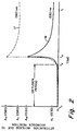
- Curve 1 shows spectral attenuation curves for a fiber that is relatively sensitive to hydrogen.
- Curve 10 illustrates the spectral attenuation of the fiber immediately after it was drawn. As illustrated by curve 11, the fiber experienced attenuation increases at 1330 nm, 1440 nm and 1530 nm after exposure to 0.1% hydrogen for 25 days. Attenuation increased from about 0.2 dB/km to almost 1 dB/km at 1530 nm.
- Curve 12 shows that after 153 days, attenuation decreased from its maximum value, but it never decreased to its as-drawn value at 1530 nm. Its residual value at that wavelength is about 0.3 dB/km.
- Curves 16 and 17 of Fig. 2 illustrate the manner in which attenuation increases with respect to time for this type of fiber at two of the affected wavelengths, 1530 nm and 1380 nm, respectively.
- the fiber is drawn at time t0. Very little attenuation increase above the base value of A i occurs between times t0 and t d . Attenuation rapidly increases between times t d and t m , at which time a maximum attenuation A m occurs.
- the term A m(1530) for example, refers to the maximum attenuation at 1530 nm. Thereafter, attenuation gradually decreases to a residual value at time t r .
- the residual attenuation A r is about 15 % of the maximum attenuation increase A m .
- This transient attenuation increase mechanism has what appears to be a diffusion period of several days to several hundreds of days, depending upon hydrogen concentration and ambient temperature.
- Fig. 3 schematically illustrates the occurrence of the hydrogen diffusion/reaction process within a cross-section of fiber 20.
- Defect sites 21, 21' can be located in core 22, cladding 23 or both. It is hypothesized that these defect sites are formed under certain drawing conditions.
- the concentration of defect sites within the experimental glass fiber samples tested which react with hydrogen was typically less than 100 ppb.
- An installed optical fiber is subjected to some source of hydrogen such as air or other atmosphere that surrounds the fiber.
- Hydrogen molecules 24 diffuse inwardly from the hydrogen source 25 outside the cladding 23.
- molecules 24 react with defect sites to form reacted sites 21' which are located beyond some radius represented by dashed line 26.
- Time delay t d of Fig. 2 results from the diffusion time of the hydrogen molecules along with the reactive consumption of the hydrogen molecules at reactive defect sites in the cladding glass until the hydrogen reaches the light propagating region of the fiber.
- the hydrogen molecules After the hydrogen molecules have reacted with essentially all of the defect sites at locations of radii beyond the light propagation region of the fiber, they begin to react with sites that are located in the light propagation region, thereby causing an attenuation increase.
- the magnitude of the attenuation increase which appears to be related to the number of defects in the light propagating region of the fiber, has been known to increase the attenuation from a base value less than about 0.2 dB/km to more than 1.0 dB/km at 1530 nm.
- the maximum transient attenuation lasts for only a few hours at room temperature.
- the aforementioned Nagasawa et al. OFC/IOOC '87 publication suggests that the attenuation increase is due to a weakened H-H bond when a hydrogen bond is formed with a peroxy radical.
- the present method should therefore be effective to reduce attenuation in germanate as well as silicate glasses since both of these kinds of glasses contain peroxy radicals.
- An object of the present invention is to provide a method for producing an optical fiber wherein the temporary attenuation increase due to hydrogen diffusion into the core is reduced to the extent that it has no practical significance. Another object is to provide a method for producing an optical fiber having reduced residual attenuation.
- the present invention relates to a method of manufacturing an optical fiber that is protected at least partially from latent attenuation increase due to hydrogen.
- the drawn optical fiber is subjected to a hydrogen-containing gas that can be present in the draw furnace and/or in a tube immediately adjacent the furnace.
- the gas contains an amount of hydrogen sufficient to form an optical fiber that experiences little or no attenuation increase at 1530 nm when it is subjected to hydrogen after it is drawn.
- attenuation of the fiber, as drawn is improved in the 600-800 nm wavelength range.
- the draw gas should contain at least 0.1 volume percent hydrogen to be effective.
- the maximum concentration of hydrogen in the draw gas is should be limited to a value that is insufficient to cause the residual hydrogen in the gas exiting from the furnace to violently react with oxygen in the ambient atmosphere.
- the draw gas can contain up to about 12 volume percent hydrogen without employing a draw furnace having special precautions. If such precautions are designed into the draw furnace, the draw gas can contain up to 100 percent hydrogen.
- the furnace could contain means for exhausting the draw gas from the furnace and means for preventing the flow of air into the furnace.
- Fig. 1 is a graph illustrating the spectral attenuation of an optical fiber as-drawn and after being subjected to 0.1% hydrogen for 25 and 153 days.
- Fig. 2 shows the attenuation increase with respect to time at 1530 and 1380 nm.
- Fig. 3 is a schematic illustration of the diffusion of hydrogen into an optical fiber.
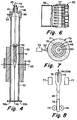
- Fig. 4 is a schematic illustration of an optical fiber draw furnace.
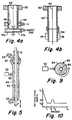
- Figs. 4a and 4b schematically illustrate modifications of the furnace of Fig. 4.
- Fig. 5 illustrates the application of successive coatings of glass particles to a mandrel.
- Fig. 6 is a fragmentary cross-sectional view of a conventional flame hydrolysis burner.
- Fig. 7 illustrates the application of additional coatings of glass particles to a mandrel.
- Fig. 8 is a schematic diagram illustrating the drawing of a rod from the consolidated preform.
- Fig. 9 illustrates the application of a coating of cladding glass particles to the rod produced by the method of Fig. 8.
- Fig. 10 is a refractive index profile of the resultant fiber.
- the transient, hydrogen-sensitive attenuation phenomenon can be eliminated or substantially reduced, i.e. it can be reduced to the extent that it is of no practical significance, by drawing the fiber in a hydrogen containing atmosphere.
- Fig. 4 illustrates the essential portion of a draw furnace that can be employed to carry out the present method.
- Insulation 30 and radio frequency coil 31 surround a portion of muffle 32 which is formed of a susceptor material such as zirconia.
- Broken line 33 represents the zone of highest temperature generated within the muffle.
- a pipe 34 for supplying gas to muffle 32 extends through annular member 36 which is situated on top of muffle 32.
- End cap 38 which is sealed to member 36, includes a sleeve 40 through which blank support rod 42 extends.
- Sealing member 44 of metallic foil or the like surrounds sleeve 40 and the adjacent portion of rod 42, to which it is sealed by O-ring 43. That end of muffle 32 from which fiber 46 is drawn can be provided with iris means 39a, 39b.
- the aperture in the iris means is initially large but is narrowed after the fiber drawing process begins.
- Draw blank 41 can be made by any known technique such as modified chemical vapor deposition (MCVD), vapor axial deposition (VAD) and outside vapor deposition (OVD); fibers drawn from blanks produced by all of these processes can be affected by the transient, hydrogen-sensitive attenuation phenomenon.
- Blank 41 is secured to rod 42 by any well known means such as slotted glass handle 45.
- rod 42 descends slowly through muffle 32 to maintain the root portion of fiber 46 and the tapered portion of blank 41 at the proper temperatures for drawing.
- the drawing temperature depends upon the composition of the blank, temperatures between 2050 o C and 2150 o C being common for high silica content blanks.
- the draw gas flowing over the draw blank during the fiber drawing process contains a sufficient amount of hydrogen to stabilize the fiber with respect to subsequent hydrogen attenuation increases.
- the draw gas mixture should contain at least 0.1 volume percent hydrogen in order to be effective.
- the balance of the draw gas mixture may be an inert gas, such as helium, argon, nitrogen, or the like, and it may optionally contain a reactive gas such as air, oxygen or the like depending upon the composition of the fiber.
- the preferred draw gas comprises a mixture of helium and hydrogen. Since hydrogen is highly reactive with oxygen, the maximum concentration of hydrogen in the draw furnace should be about 12 volume percent if the furnace does not contain means for excluding air or oxygen. Care should be taken to determine the maximum safe hydrogen concentration for any particular furnace design. Hydrogen which is present in the high temperature draw furnace rapidly diffuses into the fiber where it remains essentially trapped and reactive with defect sites as the fiber cools.
- Fig. 4a wherein elements similar to those shown in Fig. 4 are represented by primed reference numerals.
- gas chamber sections 47a and 47b can be joined to form a gas lock to which inert gas is supplied.
- the inert gas flows through the top and bottom apertures of chamber 47a, 47b.
- the flow of inert gas from the bottom gas chamber aperture excludes air from the furnace.
- the hydrogen draw gas along with the remainder of the inert gas from chamber 47a, 47b is vented through apertures 48 and exhaust manifold 49.
- Residence time can be increased by lowering draw rate.
- fiber residence time can be increased by adding an extension to the furnace.
- Residence time can also be increased by employing an apparatus shown in Fig. 4b wherein elements similar to those shown in Fig. 4 are represented by primed reference numerals.
- Heating means 55 surrounds furnace extension 54 through which fiber 46' passes after it exits furnace muffle 32'. The fiber is subjected to an elevated temperature as it passes through extension 55. Since hydrogen flows from the muffle and through the extension, the time period during which the fiber is subjected to hydrogen at an elevated temperature is increased.
- alumina mandrel 50 was inserted into glass tube 51 having protrusions 52.
- the outside diameter of the mandrel tapered from 5.5 mm to 6.5 mm over its 107 cm length.
- the ends of mandrel 50 were mounted in a lathe where it was rotated and translated.
- Burner 53 was positioned 13.7 cm from mandrel 50.
- Orifice 56 centrally located in burner face 57 (see Fig. 6), is surrounded by concentric rings of orifices 58, 59 and 60.
- Reactant compounds emanate from orifice 56 where they are heated by a flame produced by fuel gas and oxygen emanating from orifices 59. The reactant compounds oxidize in the flame to form glass particle stream 62 which is directed toward mandrel 50.
- An “inner shield” of oxygen emanates from orifices 58 to prevent the reaction of reactant compounds at the burner face.
- An “outer shield” stream of oxygen emanates from orifices 60.
- This burner design is somewhat similar to that disclosed in U.S. Patent No.
- Auxiliary burners 63 directed flames toward the ends of the porous glass preform during deposition.
- the use of auxiliary burners is taught in U.S. Patent No. 4,810,276.
- the system for delivering the gas-vapor mixture to the burner was similar to that disclosed in U.S. Patent No. 4,314,837.
- Liquid SiCl4 was maintained at 79 o C in a first container, and liquid GeCl4 was maintained at 100 o C in second container, thus producing vapor at about 20 psi.
- vapors were metered from the first and second containers and were premixed oxygen before being supplied to burner orifice 56.
- the burner traversed a 70 cm section of mandrel in 30 seconds.
- An acetylene torch supported on the burner was first employed to deposit carbon particles on the mandrel during one burner pass to facilitate removal of the porous preform.
- a porous glass core preform 72 was then formed by traversing burner 53 along mandrel 50 for 400 minutes. Each coating was formed by traversing the mandrel many times with respect to burner 53 to cause a build-up of many layers of glass particles. The burner made additional passes in the vicinity of protrusions 52 in order to strengthen the bond between the tube and preform.
- SiCl4 was ramped from 2.6 slpm to 4 slpm during the first 274 minutes, and it remained constant for the remainder of the run.
- coating 68 GeCl4 initially flowed to the burner at a rate of 0.4 slpm, and it decreased linearly to 0.1 slpm during the first 108 minutes. The GeCl4 then further decreased to zero during the next 11 minutes. Coating 69 was formed by flowing only SiCl4 to the burner for the next 84 minutes. During the formation of coating 70, GeCl4 was ramped from zero to 0.2 slpm in 8 minutes, it remained constant for about 10 minutes, and it was linearly ramped to zero during the next 11 minutes. Another coating of SiO2 was deposited by flowing only SiCl4 to the burner for the last 168 minutes of the run.
- the preform was removed from the lathe, and the mandrel was removed through tube 51, thereby leaving a longitudinal aperture in the porous preform.
- Protrusions 52 caused tube 51 to adhere to the preform; that tube remained at one end of the preform to provide support for subsequent processing.
- the preform was then dried and consolidated in accordance with the teachings of U.S. Patent No. 4,125,388 (Powers 2A).
- a drying gas consisting of 5 volume percent chlorine and 95 volume percent helium was flowed through tube 51 and into the preform aperture.
- a helium flushing gas flowed upwardly through the muffle.
- the preform was gradually lowered into a consolidation furnace muffle, thereby forming consolidated preform 75.
- Consolidated preform 75 was inserted into the apparatus of Fig. 8, a conventional draw furnace wherein the tip of preform 75 was heated by means 77 to 1900 o .
- a vacuum connection was affixed to the upper end of the preform.
- One end of silica rod 78 was fused to the lower end of the preform, and the other end of the rod was engaged by motor-driven tractors 79, thereby causing rod 80 to be drawn from preform.
- the end of preform 72 was stretched so that aperture 76 was either very narrow or completely closed, the aperture was evacuated.
- the lower end of the preform was pulled downwardly at a rate of about 15 cm/min, and its diameter decreased, the evacuated aperture 75 collapsed.
- the diameter of the resultant rod 78 was 7 mm.
- a plurality of 90 cm sections were severed from rod 78, and each section 83 was supported in a lathe where it functioned as a mandrel for the deposition of additional cladding glass particles (Fig. 9).
- the flow of SiCl4 vapor was linearly ramped from 2.5 to 4.5 slpm for about 400 minutes.
- burner 53 traversed rod 83 at a rate of about 2 cm/sec. This overclad process continued until a coating of SiO2 particles having an outside diameter of 60 mm was deposited to form composite preform 85.
- Each preform was gradually inserted into a consolidation furnace muffle where it was consolidated at a maximum temperature of 1450 o C while a mixture of 98.75 volume percent helium and 1.25 volume percent chlorine flowed upwardly through the muffle.
- Draw blank A was inserted into a draw furnace which was similar to that illustrated in Fig. 4.
- the inside diameter of the furnace muffle was 66 mm, and the maximum temperature at line 33 was about 2050 o C.
- a plurality of 5 km lengths of single-mode fiber having an outside diameter of 125 ⁇ m were drawn at a rate of 2.5 meters per second.
- fiber A a gas mixture consisting of 2.0 slpm helium and 0.25 slpm hydrogen was flowed into pipe 34 and downwardly over the blank.
- the draw gas mixture thus contained 11.1 volume percent hydrogen.
- One of these fibers is designated fiber A.
- the second half of the draw blank was drawn under similar conditions except that a draw gas consisting of 2.0 lpm helium flowed into pipe 34.
- a draw gas consisting of 2.0 lpm helium flowed into pipe 34.
- One of these fibers is designated fiber B.
- the refractive index profile of fibers A and B is shown in Fig. 10.
- the maximum concentration of GeO2 in the inner core region was about 20 wt %, thereby providing a delta of 0.96% with respect to the silica cladding.
- the ring of increased refractive index between r2 and r3 had a GeO2 concentration of about 4.6 wt % and exhibited a delta of about 0.22% with respect to the cladding.
- Radii r1, r2, r3 and r4 were 4.3 ⁇ m, 8 ⁇ m, 9.6 ⁇ m and 125 ⁇ m, respectively.
- Fibers A and B exhibited as-drawn attenuations of 7.53 dB/km and 9.56 dB/km, respectively at 630 nm. Attenuation at 630 nm due to Rayleigh scattering is 6.3 dB/km, and attenuation in excess of 6.3 dB/km is called the 630 nm excess attenuation. It has been known that the measured 630 nm excess attenuation can be used to provide an indication of the number of defect sites in an as-drawn fiber and to provide a means for predicting the maximum attenuation increase which will occur at 1530 nm and 1380 nm due to the transient, hydrogen aging phenomenon.
- the 630 nm excess attenuations of fibers A and B were 1.23 dB/km and 3.26 dB/km, respectively. This difference in attenuation was a clear indication that hydrogen treated fiber A would have fewer broken silicon-oxygen bonds, fewer peroxy radicals and would be more resistant to increased attenuation due to hydrogen aging than fiber B.
- the present method should be able to consistently produce silicate optical fibers having an attenuation lower than 8 dB/km at 630 nm.
- Fibers A and B exhibited an attenuation of about 0.2 dB/km at 1530 nm when they were drawn.
- the 1530 nm attenuation of fiber A (drawn with a hydrogen mixture) increased 0.006 dB/km after 35 hours exposure to a 1% hydrogen atmosphere.
- the attenuation of fiber B (drawn without hydrogen) increased by 0.112 dB/km after 79 hours.
- the lower 1530 nm attenuation increase and the much shorter time required for fiber A to reach maximum attenuation indicates that fiber A had many fewer hydrogen reactive defect sites than fiber B.
- Draw blank B was drawn at a faster rate of 10 m/sec into optical fiber in the furnace employed for drawing the fiber of Example 1.
- 2.0 slpm helium was flowed into pipe 34 and downwardly over the blank.
- One of the 5 km long fibers produced from the first half of the blank is designated fiber C.
- the second half of the draw blank was drawn under similar conditions except that a gas mixture consisting of 96.1 volume percent helium and 3.9 volume percent hydrogen was flowed into pipe 34 and downwardly over the blank at a rate of 2.0 slpm.
- One of these 5 km long fibers is designated fiber D.
- the dimensions and refractive index profiles of fibers C and D were the same as those of fibers A and B.
- Fiber C exhibited an attenuation increase of 0.290 dB/km at 1530 nm after 89 hours.
- Hydrogen treated fiber D exhibited an attenuation increase of 0.007 dB/km at 1530 nm after 58 hours. This example shows that the hydrogen treatment of a fiber during draw is effective in reducing the transient hydrogen attenuation phenomenon at relatively high draw rates and at lower hydrogen concentrations.
Landscapes
- Chemical & Material Sciences (AREA)
- Physics & Mathematics (AREA)
- Engineering & Computer Science (AREA)
- Life Sciences & Earth Sciences (AREA)
- General Life Sciences & Earth Sciences (AREA)
- Optics & Photonics (AREA)
- General Physics & Mathematics (AREA)
- Geochemistry & Mineralogy (AREA)
- Materials Engineering (AREA)
- Organic Chemistry (AREA)
- Chemical Kinetics & Catalysis (AREA)
- General Chemical & Material Sciences (AREA)
- Manufacturing & Machinery (AREA)
- Glass Compositions (AREA)
- Manufacture, Treatment Of Glass Fibers (AREA)
Applications Claiming Priority (2)
| Application Number | Priority Date | Filing Date | Title |
|---|---|---|---|
| US07/586,963 US5059229A (en) | 1990-09-24 | 1990-09-24 | Method for producing optical fiber in a hydrogen atmosphere to prevent attenuation |
| US586963 | 1990-09-24 |
Publications (1)
| Publication Number | Publication Date |
|---|---|
| EP0477435A1 true EP0477435A1 (de) | 1992-04-01 |
Family
ID=24347788
Family Applications (1)
| Application Number | Title | Priority Date | Filing Date |
|---|---|---|---|
| EP90125440A Withdrawn EP0477435A1 (de) | 1990-09-24 | 1990-12-24 | Verfahren zur Herstellung einer optischen Faser, optische Faser auf Silikatbasis und auf Quarzbasis |
Country Status (4)
| Country | Link |
|---|---|
| US (1) | US5059229A (de) |
| EP (1) | EP0477435A1 (de) |
| JP (1) | JPH04260634A (de) |
| AU (1) | AU7536191A (de) |
Cited By (3)
| Publication number | Priority date | Publication date | Assignee | Title |
|---|---|---|---|---|
| FR2713621A1 (fr) * | 1993-12-14 | 1995-06-16 | Alcatel Fibres Optiques | Procédé de recharge par plasma d'une préforme pour fibre optique et fibre optique issue de la préforme rechargée selon ce procédé. |
| NL1015405C2 (nl) * | 2000-06-09 | 2001-12-12 | Draka Fibre Technology Bv | Single mode optische vezel en werkwijze voor het vervaardigen van een single mode optische vezel. |
| EP0988566A4 (de) * | 1997-06-12 | 2004-04-07 | Fiberguide Ind Inc | Sonnenbeständige optische faser und verfahren |
Families Citing this family (49)
| Publication number | Priority date | Publication date | Assignee | Title |
|---|---|---|---|---|
| US5284499A (en) * | 1992-05-01 | 1994-02-08 | Corning Incorporated | Method and apparatus for drawing optical fibers |
| US5274734A (en) * | 1992-08-28 | 1993-12-28 | At&T Bell Laboratories | Article comprising a rare earth or transition metal doped optical fiber |
| US5267343A (en) * | 1992-09-03 | 1993-11-30 | The United States Of America As Represented By The United States Department Of Energy | Enhanced radiation resistant fiber optics |
| DE4339077C2 (de) * | 1993-11-16 | 1997-03-06 | Rheydt Kabelwerk Ag | Verfahren zum Ziehen einer optischen Faser und Vorrichtung zu dessen Durchführung |
| US6499318B1 (en) | 1994-03-24 | 2002-12-31 | Fitel Usa Corp. | Glass optical waveguides passivated against hydrogen-induced loss increases |
| US5838866A (en) | 1995-11-03 | 1998-11-17 | Corning Incorporated | Optical fiber resistant to hydrogen-induced attenuation |
| JP3424711B2 (ja) * | 1995-11-09 | 2003-07-07 | 住友電気工業株式会社 | 光ファイバ用ガラス体及び光ファイバ |
| US6289698B1 (en) | 1996-08-02 | 2001-09-18 | Corning Incorporated | Method of making a fiber preform with increases in alumina concentration at radial distances |
| CA2267916A1 (en) * | 1996-10-25 | 1998-05-07 | Corning Incorporated | Apparatus and method for reducing break sources in drawn fibers |
| EP0963356A4 (de) * | 1996-10-25 | 2000-06-14 | Corning Inc | Vorrichtung und verfahren zum reduzieren des brechens von fasern gezogen von vorformen |
| ID24704A (id) | 1997-07-15 | 2000-08-03 | Corning Inc | Mengurangi sensitifitas h2 pada serat optik |
| US6381990B1 (en) * | 1999-02-26 | 2002-05-07 | Corning Incorporated | Draw furnace sealing assembly and method |
| EP1243568B1 (de) * | 1999-05-27 | 2013-03-06 | Sumitomo Electric Industries, Ltd. | Herstellungsverfahren für optische fasern |
| NL1012616C2 (nl) * | 1999-07-16 | 2001-01-17 | Plasma Optical Fibre Bv | Werkwijze ter vervaardiging van een voorvorm, alsmede vezel verkregen uit een dergelijke voorvorm. |
| JP4356155B2 (ja) * | 1999-10-12 | 2009-11-04 | 住友電気工業株式会社 | 光ファイバの製造方法 |
| JP2001163632A (ja) * | 1999-12-13 | 2001-06-19 | Sumitomo Electric Ind Ltd | 光ファイバ製造方法および光ファイバ製造装置 |
| DE10027263B4 (de) * | 2000-05-31 | 2011-11-24 | Jenoptik Laser Gmbh | Verfahren zur Herstellung einer Lichtleitfaser auf SiO2-Basis zur Übertragung einer hohen Lichtleistungsdichte |
| US6739155B1 (en) * | 2000-08-10 | 2004-05-25 | General Electric Company | Quartz making an elongated fused quartz article using a furnace with metal-lined walls |
| US6779363B1 (en) * | 2000-09-29 | 2004-08-24 | Corning Incorporated | Method for pregobbing an optical fiber preform and system producing optical fiber therefrom |
| WO2002046114A1 (en) * | 2000-12-05 | 2002-06-13 | Sumitomo Electric Industries, Ltd. | Method of producing optical fiber |
| US6904772B2 (en) * | 2000-12-22 | 2005-06-14 | Corning Incorporated | Method of making a glass preform for low water peak optical fiber |
| KR100393612B1 (ko) * | 2001-01-29 | 2003-08-02 | 삼성전자주식회사 | 비접촉식으로 광섬유 편광모드분산 제어를 위한 광섬유인출 장치 |
| JP2002234750A (ja) * | 2001-02-01 | 2002-08-23 | Shinetsu Quartz Prod Co Ltd | 光ファイバ用石英ガラス母材の製造方法 |
| JP4423794B2 (ja) * | 2001-02-21 | 2010-03-03 | 住友電気工業株式会社 | 光ファイバの線引き方法 |
| US20020134530A1 (en) * | 2001-03-20 | 2002-09-26 | American Air Liquide, Inc. | Heat transfer fluids and methods of making and using same |
| US20020129622A1 (en) * | 2001-03-15 | 2002-09-19 | American Air Liquide, Inc. | Heat transfer fluids and methods of making and using same |
| US6668582B2 (en) * | 2001-04-20 | 2003-12-30 | American Air Liquide | Apparatus and methods for low pressure cryogenic cooling |
| US6651358B2 (en) | 2001-04-30 | 2003-11-25 | American Air Liquide, Inc. | Heat transfer fluids and methods of making and using same comprising hydrogen, helium and combinations thereof |
| US6574972B2 (en) | 2001-04-30 | 2003-06-10 | L'air Liquide - Societe' Anonyme A' Directoire Et Conseil De Surveillance Pour L'etude Et L'exploitation Des Procedes Georges Claude | Low temperature heat transfer methods |
| US6892012B2 (en) * | 2001-05-18 | 2005-05-10 | Fujikura, Ltd. | Optical fiber bundle unit for transmitting ultraviolet light |
| US20020178762A1 (en) * | 2001-06-01 | 2002-12-05 | Foster John D. | Methods and apparatus for forming and controlling the diameter of drawn optical glass fiber |
| US20020197005A1 (en) * | 2001-06-26 | 2002-12-26 | Chang Kai H. | Method and apparatus for fabricating optical fiber using adjustment of oxygen stoichiometry |
| US20030084685A1 (en) * | 2001-11-02 | 2003-05-08 | Jds Uniphase Corporation | Method of making an optical fiber or preform having a reduced hydrogen content |
| US6856739B2 (en) * | 2001-11-07 | 2005-02-15 | Jds Uniphase Corporation | Optical fiber for resisting hydrogen-induced loss |
| US20030200772A1 (en) * | 2002-04-30 | 2003-10-30 | Foster John D. | Methods and apparatus for forming optical fiber |
| US7565820B2 (en) * | 2002-04-30 | 2009-07-28 | Corning Incorporated | Methods and apparatus for forming heat treated optical fiber |
| US7079736B2 (en) * | 2002-06-28 | 2006-07-18 | The Furukawa Electric Co., Ltd. | Optical fiber for WDM system and manufacturing method thereof |
| EP1422202A1 (de) * | 2002-11-25 | 2004-05-26 | Alcatel | Herstellungsmethode für optische Fasern |
| US20040223694A1 (en) * | 2003-04-04 | 2004-11-11 | Dower William V. | Method and apparatus for the photosensitization of optical fiber |
| JP3847269B2 (ja) * | 2003-04-15 | 2006-11-22 | 信越化学工業株式会社 | 耐水素特性に優れた光ファイバの製造方法 |
| US20070022786A1 (en) * | 2003-04-28 | 2007-02-01 | Foster John D | Methods and apparatus for forming heat treated optical fiber |
| JPWO2005049516A1 (ja) * | 2003-11-18 | 2007-06-07 | 株式会社フジクラ | 光ファイバ裸線の線引方法、光ファイバ素線の製造方法、光ファイバ素線 |
| JP2007063030A (ja) * | 2005-08-29 | 2007-03-15 | Fujikura Ltd | 光ファイバ裸線の製造方法、光ファイバ素線の製造方法と製造装置並びに光ファイバ素線 |
| US8074474B2 (en) * | 2007-11-29 | 2011-12-13 | Corning Incorporated | Fiber air turn for low attenuation fiber |
| JP2011230987A (ja) * | 2010-04-30 | 2011-11-17 | Sumitomo Electric Ind Ltd | ガラス母材製造方法 |
| EP2584340A1 (de) * | 2011-10-20 | 2013-04-24 | Draka Comteq BV | Wasserstoffmessfaser und Wasserstoffsensor |
| NL2015161B1 (en) * | 2015-07-13 | 2017-02-01 | Draka Comteq Bv | A method for preparing a primary preform by etching and collapsing a deposited tube. |
| FI127774B (en) * | 2016-09-14 | 2019-02-15 | Rosendahl Nextrom Gmbh | Sealing arrangement in a pull-through oven |
| CN109678339B (zh) * | 2018-12-29 | 2023-10-20 | 通鼎互联信息股份有限公司 | 一种使用h2的光纤拉丝加热炉装置和方法 |
Citations (1)
| Publication number | Priority date | Publication date | Assignee | Title |
|---|---|---|---|---|
| US4685945A (en) * | 1984-02-06 | 1987-08-11 | Friedemann Freund | Method of processing high purity low-OH vitreous silica fibers |
Family Cites Families (6)
| Publication number | Priority date | Publication date | Assignee | Title |
|---|---|---|---|---|
| JPS6075802A (ja) * | 1983-10-03 | 1985-04-30 | Sumitomo Electric Ind Ltd | イメ−ジフアイバの製造方法 |
| GB2149392A (en) * | 1983-11-11 | 1985-06-12 | Central Electr Generat Board | Surface treatment of glass |
| GB2156336A (en) * | 1984-03-27 | 1985-10-09 | Standard Telphones And Cables | Method of coating infrared optical fibres |
| NL8402799A (nl) * | 1984-09-13 | 1986-04-01 | Philips Nv | Werkwijze en inrichting voor het vervaardigen van een optische vezel met een kunststofbekleding. |
| GB2164934B (en) * | 1984-09-29 | 1988-10-05 | Stc Plc | Optical fibres |
| IT1184909B (it) * | 1985-03-18 | 1987-10-28 | Cselt Centro Studi Lab Telecom | Procedimento ed apparecchiatura per la riduzione dei difetti di volume e di superficie nelle fibre ottiche in silice |
-
1990
- 1990-09-24 US US07/586,963 patent/US5059229A/en not_active Expired - Lifetime
- 1990-12-24 EP EP90125440A patent/EP0477435A1/de not_active Withdrawn
-
1991
- 1991-04-24 AU AU75361/91A patent/AU7536191A/en not_active Abandoned
- 1991-09-19 JP JP3266822A patent/JPH04260634A/ja active Pending
Patent Citations (1)
| Publication number | Priority date | Publication date | Assignee | Title |
|---|---|---|---|---|
| US4685945A (en) * | 1984-02-06 | 1987-08-11 | Friedemann Freund | Method of processing high purity low-OH vitreous silica fibers |
Non-Patent Citations (2)
| Title |
|---|
| PATENT ABSTRACTS OF JAPAN, unexamined applications, C field, vol. 13, no. 556, December 11, 1989 THE PATENT OFFICE JAPANESE GOVERNMENT page 47 C 664 * |
| PATENT ABSTRACTS OF JAPAN, unexamined applications, C field, vol. 14, no. 382, August 17, 1990 THE PATENT OFFICE JAPANESE GOVERNMENT page 127 C 749 * |
Cited By (7)
| Publication number | Priority date | Publication date | Assignee | Title |
|---|---|---|---|---|
| FR2713621A1 (fr) * | 1993-12-14 | 1995-06-16 | Alcatel Fibres Optiques | Procédé de recharge par plasma d'une préforme pour fibre optique et fibre optique issue de la préforme rechargée selon ce procédé. |
| EP0658520A1 (de) * | 1993-12-14 | 1995-06-21 | Alcatel Fibres Optiques | Verfahren zur Änderung der elektrischen Ladung einer Vorform für optische Fasern mittels Plasma und optische Faser, hergestellt aus einer Vorform mit veränderter Ladung nach diesem Verfahren |
| US5522007A (en) * | 1993-12-14 | 1996-05-28 | Alcatel Fibres Optiques | Method of building up an optical fiber preform by plasma deposition, and an optical fiber obtained from the preform built up by the method |
| EP0988566A4 (de) * | 1997-06-12 | 2004-04-07 | Fiberguide Ind Inc | Sonnenbeständige optische faser und verfahren |
| NL1015405C2 (nl) * | 2000-06-09 | 2001-12-12 | Draka Fibre Technology Bv | Single mode optische vezel en werkwijze voor het vervaardigen van een single mode optische vezel. |
| WO2002008811A1 (en) * | 2000-06-09 | 2002-01-31 | Draka Fibre Technology B.V. | Single mode optical fibre, and method for the manufacture of a single mode optical fibre |
| US6754423B2 (en) | 2000-06-09 | 2004-06-22 | Draka Fibre Technology B.V. | Single mode optical fibre, and method for the manufacture of a single mode optical fibre |
Also Published As
| Publication number | Publication date |
|---|---|
| JPH04260634A (ja) | 1992-09-16 |
| AU7536191A (en) | 1992-03-26 |
| US5059229A (en) | 1991-10-22 |
Similar Documents
| Publication | Publication Date | Title |
|---|---|---|
| US5059229A (en) | Method for producing optical fiber in a hydrogen atmosphere to prevent attenuation | |
| CA1123684A (en) | Method of making dry optical waveguides | |
| US5320658A (en) | Process of drawing optical fiber | |
| EP0139348B1 (de) | Optische Faser und Verfahren zu deren Herstellung | |
| CN107074613B (zh) | 在还原气氛中制备光纤的方法 | |
| US6189342B1 (en) | Method of making segmented core optical waveguide preforms | |
| US9878943B2 (en) | Optical fiber with reducing hydrogen sensitivity | |
| KR19990007119A (ko) | 1385nm에서 저손실되는 광학 섬유 및 그 제조 방법 | |
| EP0177040B1 (de) | Verfahren zur Herstellung einer Glasvorform für optische Fasern | |
| WO2001047822A1 (en) | Low water peak optical waveguide and method of manufacturing same | |
| US4504297A (en) | Optical fiber preform manufacturing method | |
| US6438999B1 (en) | Decreased H2 sensitivity in optical fiber | |
| JPH01239035A (ja) | 光ファイバの製造方法およびその装置 | |
| EP0100174B1 (de) | Verfahren zur Herstellung einer optischen Faser | |
| US20240069272A1 (en) | Microstructured optical fiber and preform for same | |
| JP4540034B2 (ja) | 還元剤を用いたスート・プリフォームの処理 | |
| EP0164103B1 (de) | Verfahren zur Herstellung einer Glasvorform für optische Fasern, die in der Umhüllung Fluor enthalten | |
| US6474107B1 (en) | Fluorinating an optical fiber preform in a pure aluminum oxide muffle tube | |
| US4784465A (en) | Method of making glass optical fiber | |
| JP2007508227A (ja) | 光ファイバとそのプリフォームを製造する方法 | |
| HK100494A (en) | Method for making optical fibers comprising fluorine-doped glass | |
| Plotnichenko et al. | Influence of molecular hydrogen diffusion on concentration and distribution of hydroxyl groups in silica fibers | |
| US9025922B2 (en) | Optical fiber and method for manufacturing silica glass | |
| EP0164127A2 (de) | Verfahren zur Herstellung einer Glasvorform für optische Fasern | |
| JPH0442340B2 (de) |
Legal Events
| Date | Code | Title | Description |
|---|---|---|---|
| PUAI | Public reference made under article 153(3) epc to a published international application that has entered the european phase |
Free format text: ORIGINAL CODE: 0009012 |
|
| AK | Designated contracting states |
Kind code of ref document: A1 Designated state(s): DE FR GB IT |
|
| STAA | Information on the status of an ep patent application or granted ep patent |
Free format text: STATUS: THE APPLICATION HAS BEEN WITHDRAWN |
|
| 18W | Application withdrawn |
Withdrawal date: 19920702 |