EP0477466B1 - Appareil à implanter une lentille intraoculaire pliée en matière élastique en particulier une lentille en silicone - Google Patents
Appareil à implanter une lentille intraoculaire pliée en matière élastique en particulier une lentille en silicone Download PDFInfo
- Publication number
- EP0477466B1 EP0477466B1 EP91107164A EP91107164A EP0477466B1 EP 0477466 B1 EP0477466 B1 EP 0477466B1 EP 91107164 A EP91107164 A EP 91107164A EP 91107164 A EP91107164 A EP 91107164A EP 0477466 B1 EP0477466 B1 EP 0477466B1
- Authority
- EP
- European Patent Office
- Prior art keywords
- housing
- lens
- sleeve
- implantation tool
- spindle
- Prior art date
- Legal status (The legal status is an assumption and is not a legal conclusion. Google has not performed a legal analysis and makes no representation as to the accuracy of the status listed.)
- Expired - Lifetime
Links
- 229920001296 polysiloxane Polymers 0.000 title claims abstract description 5
- 239000000463 material Substances 0.000 title claims abstract 3
- 239000002775 capsule Substances 0.000 claims abstract description 13
- 238000002513 implantation Methods 0.000 claims description 25
- 230000008878 coupling Effects 0.000 claims description 9
- 238000010168 coupling process Methods 0.000 claims description 9
- 238000005859 coupling reaction Methods 0.000 claims description 9
- 238000006073 displacement reaction Methods 0.000 claims 1
- 239000007943 implant Substances 0.000 abstract description 11
- 239000013013 elastic material Substances 0.000 description 2
- 208000002177 Cataract Diseases 0.000 description 1
- 210000000078 claw Anatomy 0.000 description 1
- 238000010276 construction Methods 0.000 description 1
- 230000007717 exclusion Effects 0.000 description 1
- 238000003780 insertion Methods 0.000 description 1
- 230000037431 insertion Effects 0.000 description 1
- 230000001105 regulatory effect Effects 0.000 description 1
- 238000005096 rolling process Methods 0.000 description 1
- 239000007779 soft material Substances 0.000 description 1
Images
Classifications
-
- A—HUMAN NECESSITIES
- A61—MEDICAL OR VETERINARY SCIENCE; HYGIENE
- A61F—FILTERS IMPLANTABLE INTO BLOOD VESSELS; PROSTHESES; DEVICES PROVIDING PATENCY TO, OR PREVENTING COLLAPSING OF, TUBULAR STRUCTURES OF THE BODY, e.g. STENTS; ORTHOPAEDIC, NURSING OR CONTRACEPTIVE DEVICES; FOMENTATION; TREATMENT OR PROTECTION OF EYES OR EARS; BANDAGES, DRESSINGS OR ABSORBENT PADS; FIRST-AID KITS
- A61F2/00—Filters implantable into blood vessels; Prostheses, i.e. artificial substitutes or replacements for parts of the body; Appliances for connecting them with the body; Devices providing patency to, or preventing collapsing of, tubular structures of the body, e.g. stents
- A61F2/02—Prostheses implantable into the body
- A61F2/14—Eye parts, e.g. lenses or corneal implants; Artificial eyes
- A61F2/16—Intraocular lenses
- A61F2/1662—Instruments for inserting intraocular lenses into the eye
- A61F2/1664—Instruments for inserting intraocular lenses into the eye for manual insertion during surgery, e.g. forceps-like instruments
Definitions
- the invention relates to a device for implanting a folded intraocular lens made of rubber-elastic material, in particular silicone lens, with a tubular housing, a push rod guided in the housing in the longitudinal direction of the housing, a rotary drive for generating a rotary movement with an implantation tool arranged at one end of the housing, with which the folded Lens can be inserted through a cut opening in the eye into the lens capsule of the eye, and with a plunger on the end of the push rod facing the implant tool, which pushes the push rod in the direction of the implant tool to separate the intraocular lens from the implant tool.
- a device for implanting a folded intraocular lens made of rubber-elastic material, in particular silicone lens with a tubular housing, a push rod guided in the housing in the longitudinal direction of the housing, a rotary drive for generating a rotary movement with an implantation tool arranged at one end of the housing, with which the folded Lens can be inserted through a cut opening in the eye into the lens capsule of the eye,
- a device of this type is known from EP-A-0 363 213.
- a rack and pinion drive which is arranged separately from the tubular housing and is coupled to the housing via an elastic shaft serves as the rotary drive.
- the implantation tool is designed as a gripping tool with jaws and pliers for gripping and gripping the intraocular lens, the free end of which is velvet folded intraocular lens is inserted into the cut opening in the eye, the intraocular lens being released after use in the lens capsule by rotating the device so that it can spring back into its original lens shape.
- this device and in particular its implantation tool is complex.
- the rotation of the device required to release the intraocular lens in the lens capsule also poses a not inconsiderable risk, in particular if it is inexperienced, it can damage the lens capsule.
- the object of the invention in contrast, is to design a device of the type mentioned in such a way that it can be safely handled when inserting the folded intraocular lens into the lens capsule during a cataract operation and while avoiding any rotation of the implantation tool and thus avoiding any risk of damage to the Eye, especially the lens capsule works.
- a spindle-nut drive with spindle, ball nut and sleeve is arranged as a rotary drive in the housing, the rotational movement of which is transferable to the spindle guided in the ball nut, the ball nut being screwed to the sleeve and the sleeve by means of Guide elements in the housing is guided linearly, so that the rotational movement of the spindle in a linear movement of the sleeve is converted, that the sleeve for transmitting its linear movement to the push rod is followed by a coupling, for example a helix coupling, and that the implantation tool is tubular and has an inner diameter adapted to the folded lens.
- This device ensures that the folded lens made of rubber-elastic material is held securely in the interior of the tubular implant tool. Furthermore, it is ensured that the folded lens, with the exclusion of any torque, is used correctly and with targeted guidance in the lens capsule, so that it can unfold there and assume the desired position after unfolding in the original lens shape in the lens capsule.
- the folded lens can be inserted in such a way that, after the lens has been unfolded, the lens equator matches the equator of the lens capsule.
- the implantation tool can preferably be designed as a sterilizable storage container for the folded lens.
- the implantation tool can advantageously be attached to the housing of the remaining part of the device, which is also referred to as a manipulator.
- the adapter insert can also be adapted to the different cross-sections and cross-sectional shapes of the implantation tool be.
- the plunger can be arranged in the adapter insert or can be arranged in the tubular implant tool, in particular serving as a storage container for the folded lens.
- a uniform pushing motion of the push rod guided exactly in the housing of the manipulator for example with a fairly constant feed speed, which can be a maximum of 1 mm per second, can be achieved with the help of a rotary drive, which in particular can be a DC micromotor with adjustable speed.
- the rotary movement of the rotary drive is converted into a linear or longitudinal movement via the coupling arranged in the manipulator, in particular between the sleeve and the push rod, which is transmitted to the push rod.
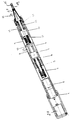
- the figure shows a longitudinal section of an embodiment of the device according to the invention for implanting a folded intraocular lens 15.
- the intraocular lens 15 is in the folded state in a tubular implant tool 19.
- the inner diameter of this tubular implant tool 19 is the thickness and the diameter or the cross-sectional shape the folded intraocular lens 15, which in particular a silicone lens is adapted.
- the tubular implantation tool is inserted in a conical adapter insert 16.
- This adapter insert 16 can be connected to the device to be explained in more detail, which can be referred to as a manipulator.
- the adapter insert 16 has two claws 18, which can be locked in their position in a housing head 14 of the tubular housing 9 of the device.
- the conical adapter insert 16 is then finally fixed to the housing 9 with the aid of an attached nut 17.
- a thrust device in the longitudinal direction of the implantation tool 19, ie along a common axis A. consisting of a push rod 12 and a plunger 20.
- the push rod 12 is guided via a miniature ball bearing 13 exactly in the housing head 14 in the longitudinal direction, ie in the direction of the axis A.
- a plunger 20 which can be provided in the conical adapter insert 16 or in the implantation tool 19.
- This plunger which is adapted to the cross section of the tube interior of the implantation tool 19, is made of a soft material, so that gentle treatment is ensured when the folded intraocular lens 15 in the implantation tool 19 is moved.
- the rod 12, the plunger 20 and the folded lens 15 are aligned with one another along the axis A.
- the manipulator has a rotary drive, which is designed in particular as an electric motor and, in the exemplary embodiment shown, as a DC micro-motor 1 which can be regulated at a speed.
- the micromotor can be fed with the aid of a battery 21.
- a planetary gear 2 is coupled to the micromotor 1.
- the rotary movement of the micromotor 1 is further transmitted via a clutch 3 connected to the planetary gear 2, which is preferably designed as a helix clutch, to a spindle 4, which in the exemplary embodiment is designed as a miniature ball screw spindle, so that the spindle 4 rotates is transferred.
- the spindle 4 is overhung in a bearing housing 6 via two ball bearings 5, in particular radial deep groove ball bearings, and is secured in the axial direction.
- the bearing housing 6 is screwed onto the tubular manipulator housing 9.
- the spindle 4 is part of a spindle-nut drive.
- the spindle 4 is guided in a ball nut 7 of the spindle-nut drive.
- the ball nut 7 is screwed to a sleeve 8.
- the sleeve 8 is longitudinally guided on the tubular manipulator housing 9 with the aid of pins 10.
- the pins 10 protrude into the interior of the tubular housing 9.
- the rotational movement of the spindle 4, which in the illustrated embodiment is preferably designed as a ball rolling spindle, is guided in a known manner in an internal thread of the ball nut 7, so that the rotation of the spindle 4 in a longitudinal movement the ball nut 7 is implemented.
- the longitudinal movement of the ball nut 7 is transmitted to the sleeve 8, which in the manner described with the aid of the fixed pins 10 in the interior of the tubular manipulator housing in the longitudinal direction, i.e. is guided in the direction of the axis A.
- the fixed pins 10 slide in the longitudinal grooves 23 of the sleeve 8.
- the linear movement in the axial direction A of the sleeve 8 is transmitted via a further coupling 11, which is also preferably designed as a helix coupling, to the push rod 12, which is mounted in the housing head 14 via the miniature ball bearing 13.
- the push rod 12 can be moved in the forward direction at a maximum feed speed of about 1 mm / sec, so that the folded intraocular lens 15 is pushed out of the implantation tool 19 into the lens capsule.
- the backward movement of the push rod 12 can be brought about by changing the direction of rotation of the DC voltage micromotor 1. The push rod 12 is then returned to its starting position.
- all bushings are preferably O-ring sealed.
- the total longitudinal extent of the device shown in the figure is approximately 215 mm.
- the length of the implant tool 19 protruding from the adapter insert 16 is approximately 10 mm.
- the feed S of the feed rod 12 is therefore also dimensioned to approximately 10 mm.
- the length of the adapter insert 16 placed on the manipulator together with the implantation tool 19 is approximately 27 mm.
- the diameter of the manipulator in the area of the battery 21 is approximately 20 mm.
Landscapes
- Health & Medical Sciences (AREA)
- Ophthalmology & Optometry (AREA)
- Cardiology (AREA)
- Oral & Maxillofacial Surgery (AREA)
- Transplantation (AREA)
- Engineering & Computer Science (AREA)
- Biomedical Technology (AREA)
- Heart & Thoracic Surgery (AREA)
- Vascular Medicine (AREA)
- Life Sciences & Earth Sciences (AREA)
- Animal Behavior & Ethology (AREA)
- General Health & Medical Sciences (AREA)
- Public Health (AREA)
- Veterinary Medicine (AREA)
- Prostheses (AREA)
Claims (10)
- Appareil pour implanter une lentille intra-oculaire pliée en matière à élasticité du type caoutchouc, en particulier une lentille en silicone, comprenant un boîtier (9) de forme tubulaire, une tige de poussée (12) guidée dans le boîtier dans la direction axiale du boîtier, une commande en rotation pour produire un mouvement de rotation, un outil d'implantation (19) prévu à une extrémité du boîtier, avec lequel la lentille pliée peut être mise en place dans l'oeil par une ouverture découpée dans l'oeil, et un poussoir (20) à l'extrémité de la tige de poussée (12) tournée vers l'outil d'implantation, qui, par coulissement de la tige de poussée (12) dans la direction de l'outil d'implantation (19), sépare la lentille intra-oculaire de l'outil d'implantation (13),
caractérisé en ce que, comme commande en rotation dans le boîtier (9), on prévoit une commande vis-écrou (22) comportant une tige de vis (4), un écrou sphérique (7) et une douille (8), dont le mouvement de rotation est transmissible à la tige de vis (4) guidée dans l'écrou sphérique (7), l'écrou sphérique (7) étant raccordé à la douille (8) et la douille (8) étant guidée linéairement dans le boîtier (9) au moyen d'éléments de guidage (10, 23), en sorte que le mouvement de rotation de la tige de vis (4) est transformé en un mouvement linéaire de la douille (8), qu'un accouplement (11) est monté à la suite de la douille (8) pour transmettre son mouvement linéaire à la tige de poussée (12), et que l'outil d'implantation (19) est de forme tubulaire et présente un diamètre intérieur adapté à la lentille pliée (15). - Appareil selon la revendication 1, caractérisé en ce que le poussoir (20) est adapté à la section de l'intérieur tubulaire de l'outil d'implantation (19).
- Appareil selon l'une des revendications 1 et 2, caractérisé en ce que l'outil d'implantation (19) peut être fixé sur le boîtier (9, 14) par l'intermédiaire d'une pièce adaptatrice (16).
- Appareil selon l'une des revendications 1 à 3, caractérisé en ce que l'outil d'implantation (19) est réalisé sous la forme d'un récipient stérilisable pour la conservation de la lentille (15).
- Appareil selon l'une des revendications 1 à 4, caractérisé en ce que le poussoir (20) est prévu dans la pièce adaptatrice (16).
- Appareil selon l'une des revendications 1 à 5, caractérisé en ce que, pour assurer le guidage linéaire de la douille (8) dans le boîtier (9), des ergots (10) sont montés fixes dans le boîtier, lesquels font saillie vers l'intérieur tubulaire du boîtier et glissent dans des rainures longitudinales (23) de la douille (8).
- Appareil selon l'une des revendications 1 à 6, caractérisé en ce que l'accouplement (11) est prévu entre la douille (8) et la tige de poussée (12).
- Appareil selon l'une des revendications 1 à 7, caractérisé en ce que l'accouplement (11) est réalisé sous la forme d'un accouplement en hélice.
- Appareil selon l'une des revendications 1 à 8, caractérisé en ce que la vitesse de translation de la tige de poussée (12) avec le poussoir (20) atteint environ 1 mm/seconde.
- Appareil selon l'une des revendications 1 à 9, caractérisé en ce que l'amplitude d'avance de la tige de poussée (12) avec le poussoir (20) atteint environ 10 mm.
Applications Claiming Priority (2)
| Application Number | Priority Date | Filing Date | Title |
|---|---|---|---|
| DE4030492 | 1990-09-26 | ||
| DE4030492A DE4030492C1 (fr) | 1990-09-26 | 1990-09-26 |
Publications (2)
| Publication Number | Publication Date |
|---|---|
| EP0477466A1 EP0477466A1 (fr) | 1992-04-01 |
| EP0477466B1 true EP0477466B1 (fr) | 1996-06-26 |
Family
ID=6415044
Family Applications (1)
| Application Number | Title | Priority Date | Filing Date |
|---|---|---|---|
| EP91107164A Expired - Lifetime EP0477466B1 (fr) | 1990-09-26 | 1991-05-03 | Appareil à implanter une lentille intraoculaire pliée en matière élastique en particulier une lentille en silicone |
Country Status (4)
| Country | Link |
|---|---|
| US (1) | US5354333A (fr) |
| EP (1) | EP0477466B1 (fr) |
| AT (1) | ATE139682T1 (fr) |
| DE (2) | DE4030492C1 (fr) |
Cited By (7)
| Publication number | Priority date | Publication date | Assignee | Title |
|---|---|---|---|---|
| US8308736B2 (en) | 2008-10-13 | 2012-11-13 | Alcon Research, Ltd. | Automated intraocular lens injector device |
| US8308799B2 (en) | 2010-04-20 | 2012-11-13 | Alcon Research, Ltd. | Modular intraocular lens injector device |
| US8579969B2 (en) | 2010-07-25 | 2013-11-12 | Alcon Research, Ltd. | Dual mode automated intraocular lens injector device |
| US8657835B2 (en) | 2012-01-27 | 2014-02-25 | Alcon Research, Ltd. | Automated intraocular lens injector device |
| US8801780B2 (en) | 2008-10-13 | 2014-08-12 | Alcon Research, Ltd. | Plunger tip coupling device for intraocular lens injector |
| US8808308B2 (en) | 2008-10-13 | 2014-08-19 | Alcon Research, Ltd. | Automated intraocular lens injector device |
| US8894664B2 (en) | 2008-02-07 | 2014-11-25 | Novartis Ag | Lens delivery system cartridge |
Families Citing this family (66)
| Publication number | Priority date | Publication date | Assignee | Title |
|---|---|---|---|---|
| US5653715A (en) * | 1993-03-09 | 1997-08-05 | Chiron Vision Corporation | Apparatus for preparing an intraocular lens for insertion |
| US5468246A (en) * | 1993-07-02 | 1995-11-21 | Iovision, Inc. | Intraocular lens injector |
| DE19538951C2 (de) | 1995-10-19 | 1998-04-30 | Detlef H Dr Holzwig | Vorrichtung zum Spreizen einer Augeniris |
| US5693057A (en) * | 1995-10-27 | 1997-12-02 | Dusek; Vaclav | Instrument for implanting foldable intraocular lenses |
| US6179843B1 (en) | 1997-06-28 | 2001-01-30 | Harold H. Weiler | Device for insertion of foldable intraocular lenses |
| AU7361898A (en) | 1997-10-24 | 1999-05-17 | Tekia, Inc. | Ophthalmologic insertor apparatus and methods of use |
| US6605093B1 (en) | 1997-10-24 | 2003-08-12 | Tekia, Inc. | Device and method for use with an ophthalmologic insertor apparatus |
| US6050999A (en) * | 1997-12-18 | 2000-04-18 | Keravision, Inc. | Corneal implant introducer and method of use |
| DE19807233A1 (de) | 1998-02-20 | 1999-08-26 | Acritec Gmbh | Vorrichtung zum Implantieren einer Intraocularlinse |
| DE19904220C2 (de) | 1999-02-03 | 2001-08-30 | Helmut Binder | Injektor zum Falten und Einbringen einer Intraokularlinse, und Behälter zum Lagern und Transportieren des Injektors |
| US6283976B1 (en) * | 2000-05-05 | 2001-09-04 | Allergan Sales Inc. | Intraocular lens implanting instrument |
| US6500181B1 (en) * | 2000-10-17 | 2002-12-31 | Valdemar Portney | Instrument for folding and inserting anterior chamber intraocular lenses |
| EP1287791B1 (fr) * | 2001-08-23 | 2009-09-09 | Anton Meyer & Co. AG | Dispositif pour implanter une lentille dans l'oeil |
| JP4138428B2 (ja) | 2002-09-27 | 2008-08-27 | 株式会社ニデック | 眼内レンズ挿入器具 |
| EP1419748B1 (fr) * | 2002-11-18 | 2006-07-19 | Anton Meyer & Co.AG | Dispositif d'injection de lentille avec bague |
| DE502004011274D1 (de) * | 2004-04-22 | 2010-07-22 | Advanced Vision Science Inc | Vorrichtung zum einsetzen verformbarer intraocularlinsen |
| RU2375015C2 (ru) * | 2004-04-22 | 2009-12-10 | Эдванст Вижн Сайенс, Инк. | Устройство для вставления деформируемых внутриглазных линз |
| EP1832247B1 (fr) | 2004-12-27 | 2015-06-24 | Hoya Corporation | Dispositif d'implantation de lentille intraoculaire |
| EP1845899B1 (fr) * | 2004-12-29 | 2011-06-29 | Bausch & Lomb Incorporated | Méthode de préparation d'injecteur préchargé de lentille intraoculaire |
| US8545512B2 (en) | 2005-01-26 | 2013-10-01 | Hoya Corporation | Intraocular lens insertion device |
| JP4836046B2 (ja) | 2005-02-24 | 2011-12-14 | Hoya株式会社 | 眼内レンズ挿入器具 |
| KR100966833B1 (ko) * | 2005-04-28 | 2010-06-29 | 나미키 세이미츠 호오세키 가부시키가이샤 | 마이크로 기어드 모터 |
| US20070005135A1 (en) * | 2005-07-01 | 2007-01-04 | Harish Makker | Intraocular lens insertion plunger with low stimulus soft tip |
| WO2007037223A1 (fr) | 2005-09-28 | 2007-04-05 | Hoya Corporation | Instrument pour insérer un cristallin artificiel |
| JP4877643B2 (ja) | 2005-12-08 | 2012-02-15 | Hoya株式会社 | 眼内レンズ挿入用器具 |
| NL2000082C2 (nl) * | 2006-05-24 | 2007-11-27 | Akkolens Int Bv | Injectie apparaat voor intraoculaire lens en toebehoren. |
| US7879090B2 (en) * | 2006-12-13 | 2011-02-01 | Bausch & Lomb Incorporated | Intraocular lens injector apparatus and methods of use |
| US20080147082A1 (en) * | 2006-12-13 | 2008-06-19 | Joel Pynson | Injector apparatus for use with intraocular lenses and methods of use |
| US20080154361A1 (en) * | 2006-12-22 | 2008-06-26 | Joel Pynson | Intraocular lens injector subassembly |
| JP5236637B2 (ja) | 2007-05-30 | 2013-07-17 | Hoya株式会社 | 眼内レンズ挿入器具及び眼内レンズ挿入装置 |
| WO2008149795A1 (fr) | 2007-05-30 | 2008-12-11 | Hoya Corporation | Outil utilisé pour l'insertion d'une lentille intraoculaire |
| JP5086713B2 (ja) | 2007-07-11 | 2012-11-28 | Hoya株式会社 | 眼内レンズ挿入器具 |
| EP2647353B1 (fr) | 2007-07-23 | 2014-12-31 | PowerVision, Inc. | Système de mise en place de lentille |
| US8968396B2 (en) | 2007-07-23 | 2015-03-03 | Powervision, Inc. | Intraocular lens delivery systems and methods of use |
| JP5254669B2 (ja) | 2008-06-05 | 2013-08-07 | Hoya株式会社 | 眼内レンズ挿入器具及びカートリッジ |
| JP5470753B2 (ja) | 2008-06-17 | 2014-04-16 | Hoya株式会社 | 眼内レンズ挿入器具 |
| JP5323420B2 (ja) | 2008-08-21 | 2013-10-23 | Hoya株式会社 | 眼内レンズ挿入器具 |
| JP5416379B2 (ja) | 2008-09-04 | 2014-02-12 | Hoya株式会社 | 眼内レンズ挿入器具 |
| CN102307543B (zh) | 2009-01-07 | 2015-10-21 | Hoya株式会社 | 眼内透镜插入器具 |
| US8545554B2 (en) * | 2009-01-16 | 2013-10-01 | Allergan, Inc. | Intraocular injector |
| JP5543495B2 (ja) | 2009-02-11 | 2014-07-09 | アルコン リサーチ, リミテッド | 眼内レンズ自動注入器装置 |
| EP3263574B1 (fr) | 2010-02-23 | 2019-04-03 | PowerVision, Inc. | Lentille intraoculaire à accomodation |
| JP5735531B2 (ja) | 2010-04-08 | 2015-06-17 | Hoya株式会社 | 眼内移植片挿入器具 |
| JP5511530B2 (ja) | 2010-06-10 | 2014-06-04 | Hoya株式会社 | 眼内レンズ挿入装置 |
| WO2012006616A2 (fr) | 2010-07-09 | 2012-01-12 | Powervision, Inc. | Dispositif de pose de lentilles intraoculaires et leurs procédés d'utilisation |
| US8535268B2 (en) | 2010-12-22 | 2013-09-17 | Alcon Research, Ltd. | Device for at least one of injection or aspiration |
| EP3928744A1 (fr) | 2011-03-24 | 2021-12-29 | Alcon Inc. | Systèmes de chargement de lentille intraoculaire et procédés d'utilisation |
| CN104379092B (zh) * | 2012-06-04 | 2016-12-14 | 爱尔康制药有限公司 | 眼内透镜插入器 |
| CA3078098C (fr) | 2012-06-12 | 2022-03-15 | Alcon Inc. | Injecteur de gaz intra-oculaire |
| EP2967842B1 (fr) | 2013-03-15 | 2020-11-04 | Alcon Inc. | Procede de reconfiguration d'une lentille intra-oculaire en vue de sa livraison a un dispositif de livraison |
| CN104994810B (zh) * | 2013-04-03 | 2018-03-02 | 诺华股份有限公司 | 自动化人工晶状体注入器装置 |
| CA2944513C (fr) | 2014-04-04 | 2022-07-05 | Jack R. Auld | Dispositif d'insertion de lentille intra-oculaire |
| US9636217B2 (en) | 2014-05-08 | 2017-05-02 | Novartis Ag | Equipment and methods used in folding and implanting foldable lenses in the eye |
| AU2016324545A1 (en) | 2015-09-16 | 2018-04-12 | Hoya Corporation | Intraocular lens insertion tool |
| JP6646987B2 (ja) | 2015-09-16 | 2020-02-14 | Hoya株式会社 | 眼内レンズ挿入器具 |
| US10172706B2 (en) * | 2015-10-31 | 2019-01-08 | Novartis Ag | Intraocular lens inserter |
| US11547555B2 (en) | 2015-12-17 | 2023-01-10 | Atrion Medical Products, Inc. | Intraocular lens delivery device and method of use |
| US10722347B2 (en) | 2015-12-17 | 2020-07-28 | Atrion Medical Products, Inc. | Intraocular lens delivery device and method of use |
| US11033382B2 (en) | 2016-06-28 | 2021-06-15 | Hoya Corporation | Intraocular lens injector |
| WO2018003853A1 (fr) | 2016-06-28 | 2018-01-04 | Hoya株式会社 | Instrument d'insertion de lentille intraoculaire |
| US11000367B2 (en) | 2017-01-13 | 2021-05-11 | Alcon Inc. | Intraocular lens injector |
| JP7162443B2 (ja) | 2018-05-16 | 2022-10-28 | Hoya株式会社 | 容器付き眼内リング挿入器 |
| JP7162445B2 (ja) | 2018-05-25 | 2022-10-28 | Hoya株式会社 | 眼内レンズ挿入器 |
| US11224537B2 (en) | 2018-10-19 | 2022-01-18 | Alcon Inc. | Intraocular gas injector |
| JP7327956B2 (ja) | 2019-03-13 | 2023-08-16 | Hoya株式会社 | 眼内レンズ挿入器具 |
| EP4734876A1 (fr) | 2023-06-30 | 2026-05-06 | Alcon Inc. | Système et procédés de compensation d'inclinaison de lentille intraoculaire |
Family Cites Families (7)
| Publication number | Priority date | Publication date | Assignee | Title |
|---|---|---|---|---|
| US4108182A (en) * | 1977-02-16 | 1978-08-22 | Concept Inc. | Reciprocation vitreous suction cutter head |
| DE2834299C2 (de) * | 1978-08-04 | 1982-08-19 | Deutsche Star Kugelhalter Gmbh, 8720 Schweinfurt | Kugelschraubtrieb |
| US4573998A (en) * | 1982-02-05 | 1986-03-04 | Staar Surgical Co. | Methods for implantation of deformable intraocular lenses |
| US4681102A (en) * | 1985-09-11 | 1987-07-21 | Bartell Michael T | Apparatus and method for insertion of an intra-ocular lens |
| US4834094A (en) * | 1987-10-07 | 1989-05-30 | Patton Medical Technologies, Inc. | "Canoe" apparatus for inserting intra-ocular lens into the eye |
| US4834095A (en) * | 1988-02-16 | 1989-05-30 | Ipco Corporation | Probe unit for electro-surgical device |
| AU623934B2 (en) * | 1988-10-07 | 1992-05-28 | Ioptex Research Inc | Intraocular lens insertion instrument |
-
1990
- 1990-09-26 DE DE4030492A patent/DE4030492C1/de not_active Expired - Fee Related
-
1991
- 1991-05-03 DE DE59107956T patent/DE59107956D1/de not_active Expired - Fee Related
- 1991-05-03 EP EP91107164A patent/EP0477466B1/fr not_active Expired - Lifetime
- 1991-05-03 AT AT91107164T patent/ATE139682T1/de not_active IP Right Cessation
-
1992
- 1992-11-20 US US07/979,368 patent/US5354333A/en not_active Expired - Fee Related
Cited By (7)
| Publication number | Priority date | Publication date | Assignee | Title |
|---|---|---|---|---|
| US8894664B2 (en) | 2008-02-07 | 2014-11-25 | Novartis Ag | Lens delivery system cartridge |
| US8308736B2 (en) | 2008-10-13 | 2012-11-13 | Alcon Research, Ltd. | Automated intraocular lens injector device |
| US8801780B2 (en) | 2008-10-13 | 2014-08-12 | Alcon Research, Ltd. | Plunger tip coupling device for intraocular lens injector |
| US8808308B2 (en) | 2008-10-13 | 2014-08-19 | Alcon Research, Ltd. | Automated intraocular lens injector device |
| US8308799B2 (en) | 2010-04-20 | 2012-11-13 | Alcon Research, Ltd. | Modular intraocular lens injector device |
| US8579969B2 (en) | 2010-07-25 | 2013-11-12 | Alcon Research, Ltd. | Dual mode automated intraocular lens injector device |
| US8657835B2 (en) | 2012-01-27 | 2014-02-25 | Alcon Research, Ltd. | Automated intraocular lens injector device |
Also Published As
| Publication number | Publication date |
|---|---|
| EP0477466A1 (fr) | 1992-04-01 |
| ATE139682T1 (de) | 1996-07-15 |
| US5354333A (en) | 1994-10-11 |
| DE4030492C1 (fr) | 1991-09-05 |
| DE59107956D1 (de) | 1996-08-01 |
Similar Documents
| Publication | Publication Date | Title |
|---|---|---|
| EP0477466B1 (fr) | Appareil à implanter une lentille intraoculaire pliée en matière élastique en particulier une lentille en silicone | |
| DE10358554B4 (de) | Chirurgisches Instrument zum Sezieren von Knochen oder anderem Gewebe mit Teleskopaufsatz | |
| DE69622563T2 (de) | Schnellkupplungsmethode und vorrichtung und chirugisches instrument für den antrieb von auswechselbaren rotierenden werkzeugen | |
| US4275893A (en) | Self-tightening keyless chuck | |
| EP1330192B1 (fr) | Outil de percage pour une perceuse chirurgicale | |
| DE2838348A1 (de) | Vorrichtung zum ausformen einer knochenoeffnung, insbesondere im hueftbein zum einsetzen einer kuenstlichen gelenkpfanne | |
| DE2834295B2 (de) | Vorrichtung zum Herstellen einer sich vom stirnseitigen Endabschnitt eines Knochens konisch verjüngenden Mantelfläche | |
| EP0222971A1 (fr) | Tournevis destiné notamment à la chirurgie | |
| EP1605837A1 (fr) | Raccord pour un porte-outil a mecanisme d'entrainement chirurgical | |
| DE4103663A1 (de) | Chirurgisches handstueck | |
| DE102011087297B4 (de) | Handwerkzeugmaschine mit einem trommelartigen Werkzeugwechselmagazin | |
| DE4414903A1 (de) | Chirurgisches Instrument | |
| DE3117795C2 (fr) | ||
| EP0670149A1 (fr) | Pièce à main droite motorisée, en particulier pour des fins médicales, de préférence pour un laboratoire médical ou dentaire | |
| CH621697A5 (fr) | ||
| EP0505599B1 (fr) | Dispositif pour le maintien du manche, en particulier d'un instrument de dentisterie | |
| DE1255059B (de) | Montagewerkzeug fuer eine Blindschraubenverbindung | |
| EP4376731B1 (fr) | Ensemble palier d'un plateau oscillant dans un composant de mécanisme de direction, et instrument chirurgical | |
| EP1709930A1 (fr) | Organe moteur, en particulier pièce à main médicale avec une pince de serrage | |
| EP0420057A1 (fr) | Focalisation des objets d'endoscope | |
| DE4445598A1 (de) | Handgeführte Werkzeugmaschine | |
| DE2937885C2 (de) | Zahnärztliches Handstück | |
| DE19737238C2 (de) | Wellenkopf, insbesondere für biegsame Wellen | |
| DE2020449A1 (de) | Schluessellos bedienbares Mehrbackenspannfutter | |
| DE102004006772B4 (de) | Schraubwerkzeug |
Legal Events
| Date | Code | Title | Description |
|---|---|---|---|
| PUAI | Public reference made under article 153(3) epc to a published international application that has entered the european phase |
Free format text: ORIGINAL CODE: 0009012 |
|
| AK | Designated contracting states |
Kind code of ref document: A1 Designated state(s): AT BE CH DE DK ES FR GB GR IT LI LU NL SE |
|
| 17P | Request for examination filed |
Effective date: 19920319 |
|
| 17Q | First examination report despatched |
Effective date: 19940705 |
|
| RAP1 | Party data changed (applicant data changed or rights of an application transferred) |
Owner name: CHIRON ADATOMED PHARMAZEUTISCHE UND MEDIZINTECHNIS |
|
| GRAH | Despatch of communication of intention to grant a patent |
Free format text: ORIGINAL CODE: EPIDOS IGRA |
|
| GRAA | (expected) grant |
Free format text: ORIGINAL CODE: 0009210 |
|
| AK | Designated contracting states |
Kind code of ref document: B1 Designated state(s): AT BE CH DE DK ES FR GB GR IT LI LU NL SE |
|
| PG25 | Lapsed in a contracting state [announced via postgrant information from national office to epo] |
Ref country code: IT Free format text: LAPSE BECAUSE OF FAILURE TO SUBMIT A TRANSLATION OF THE DESCRIPTION OR TO PAY THE FEE WITHIN THE PRE;WARNING: LAPSES OF ITALIAN PATENTS WITH EFFECTIVE DATE BEFORE 2007 MAY HAVE OCCURRED AT ANY TIME BEFORE 2007. THE CORRECT EFFECTIVE DATE MAY BE DIFFERENT FROM THE ONE RECORDED.SCRIBED TIME-LIMIT Effective date: 19960626 Ref country code: FR Effective date: 19960626 Ref country code: GR Free format text: LAPSE BECAUSE OF FAILURE TO SUBMIT A TRANSLATION OF THE DESCRIPTION OR TO PAY THE FEE WITHIN THE PRESCRIBED TIME-LIMIT Effective date: 19960626 Ref country code: GB Effective date: 19960626 Ref country code: NL Free format text: LAPSE BECAUSE OF FAILURE TO SUBMIT A TRANSLATION OF THE DESCRIPTION OR TO PAY THE FEE WITHIN THE PRESCRIBED TIME-LIMIT Effective date: 19960626 Ref country code: ES Free format text: THE PATENT HAS BEEN ANNULLED BY A DECISION OF A NATIONAL AUTHORITY Effective date: 19960626 Ref country code: DK Effective date: 19960626 |
|
| REF | Corresponds to: |
Ref document number: 139682 Country of ref document: AT Date of ref document: 19960715 Kind code of ref document: T |
|
| REF | Corresponds to: |
Ref document number: 59107956 Country of ref document: DE Date of ref document: 19960801 |
|
| PG25 | Lapsed in a contracting state [announced via postgrant information from national office to epo] |
Ref country code: SE Effective date: 19960926 |
|
| EN | Fr: translation not filed | ||
| NLV1 | Nl: lapsed or annulled due to failure to fulfill the requirements of art. 29p and 29m of the patents act | ||
| GBV | Gb: ep patent (uk) treated as always having been void in accordance with gb section 77(7)/1977 [no translation filed] |
Effective date: 19960626 |
|
| PLBE | No opposition filed within time limit |
Free format text: ORIGINAL CODE: 0009261 |
|
| STAA | Information on the status of an ep patent application or granted ep patent |
Free format text: STATUS: NO OPPOSITION FILED WITHIN TIME LIMIT |
|
| PG25 | Lapsed in a contracting state [announced via postgrant information from national office to epo] |
Ref country code: AT Free format text: LAPSE BECAUSE OF NON-PAYMENT OF DUE FEES Effective date: 19970503 |
|
| PG25 | Lapsed in a contracting state [announced via postgrant information from national office to epo] |
Ref country code: LU Free format text: LAPSE BECAUSE OF NON-PAYMENT OF DUE FEES Effective date: 19970531 Ref country code: BE Effective date: 19970531 Ref country code: CH Free format text: LAPSE BECAUSE OF NON-PAYMENT OF DUE FEES Effective date: 19970531 Ref country code: LI Free format text: LAPSE BECAUSE OF NON-PAYMENT OF DUE FEES Effective date: 19970531 |
|
| 26N | No opposition filed | ||
| BERE | Be: lapsed |
Owner name: CHIRON ADATOMED PHARMAZEUTISCHE UND MEDIZINTECHNI Effective date: 19970531 |
|
| REG | Reference to a national code |
Ref country code: CH Ref legal event code: PL |
|
| PG25 | Lapsed in a contracting state [announced via postgrant information from national office to epo] |
Ref country code: DE Free format text: LAPSE BECAUSE OF NON-PAYMENT OF DUE FEES Effective date: 19980203 |