EP0477610A1 - Eléments de couplage enfichables multipolaires pour conducteurs électriques - Google Patents
Eléments de couplage enfichables multipolaires pour conducteurs électriques Download PDFInfo
- Publication number
- EP0477610A1 EP0477610A1 EP91114898A EP91114898A EP0477610A1 EP 0477610 A1 EP0477610 A1 EP 0477610A1 EP 91114898 A EP91114898 A EP 91114898A EP 91114898 A EP91114898 A EP 91114898A EP 0477610 A1 EP0477610 A1 EP 0477610A1
- Authority
- EP
- European Patent Office
- Prior art keywords
- slide
- housing
- control member
- coupling half
- half according
- Prior art date
- Legal status (The legal status is an assumption and is not a legal conclusion. Google has not performed a legal analysis and makes no representation as to the accuracy of the status listed.)
- Granted
Links
- 238000010168 coupling process Methods 0.000 title claims abstract description 48
- 238000005859 coupling reaction Methods 0.000 title claims abstract description 48
- 230000008878 coupling Effects 0.000 title claims abstract description 47
- 239000004020 conductor Substances 0.000 title 1
- 230000000295 complement effect Effects 0.000 claims abstract description 8
- 238000003780 insertion Methods 0.000 claims description 11
- 230000037431 insertion Effects 0.000 claims description 11
- 230000005405 multipole Effects 0.000 claims description 2
- 230000007704 transition Effects 0.000 claims description 2
- 238000009413 insulation Methods 0.000 claims 1
- 238000012546 transfer Methods 0.000 abstract description 4
- 230000013011 mating Effects 0.000 abstract description 3
- 238000006073 displacement reaction Methods 0.000 abstract 1
- 238000007654 immersion Methods 0.000 description 7
- 230000002349 favourable effect Effects 0.000 description 3
- 230000009471 action Effects 0.000 description 2
- 230000005540 biological transmission Effects 0.000 description 2
- 230000000694 effects Effects 0.000 description 2
- 210000002105 tongue Anatomy 0.000 description 2
- 230000015572 biosynthetic process Effects 0.000 description 1
- 230000000903 blocking effect Effects 0.000 description 1
- 238000013461 design Methods 0.000 description 1
- 230000009977 dual effect Effects 0.000 description 1
- 238000000605 extraction Methods 0.000 description 1
- 238000007373 indentation Methods 0.000 description 1
- 238000009434 installation Methods 0.000 description 1
- 238000000034 method Methods 0.000 description 1
- 230000004048 modification Effects 0.000 description 1
- 238000012986 modification Methods 0.000 description 1
- 230000003287 optical effect Effects 0.000 description 1
- 230000008569 process Effects 0.000 description 1
- IHQKEDIOMGYHEB-UHFFFAOYSA-M sodium dimethylarsinate Chemical class [Na+].C[As](C)([O-])=O IHQKEDIOMGYHEB-UHFFFAOYSA-M 0.000 description 1
- 238000013519 translation Methods 0.000 description 1
Images

Classifications
-
- H—ELECTRICITY
- H01—ELECTRIC ELEMENTS
- H01R—ELECTRICALLY-CONDUCTIVE CONNECTIONS; STRUCTURAL ASSOCIATIONS OF A PLURALITY OF MUTUALLY-INSULATED ELECTRICAL CONNECTING ELEMENTS; COUPLING DEVICES; CURRENT COLLECTORS
- H01R13/00—Details of coupling devices of the kinds covered by groups H01R12/70 or H01R24/00 - H01R33/00
- H01R13/40—Securing contact members in or to a base or case; Insulating of contact members
- H01R13/42—Securing in a demountable manner
- H01R13/436—Securing a plurality of contact members by one locking piece or operation
- H01R13/4367—Insertion of locking piece from the rear
Definitions
- the invention is directed to a multi-pole coupling half of the type specified in the preamble of claim 1. This can be designed as a plug with male contact members or as a socket with female contact members.
- the housing is equipped with a family of parallel bores for receiving and holding the contact members and has a slot crossing these, in which a plate acting as a slide can be moved in a push-like manner.
- the perforated plate has a hole pattern adapted to the bore profile and, when fully inserted, engages in recesses in the contact members, as a result of which these are secured in the housing.
- a so-called "comb" could also be used to secure the received contact members, the comb teeth of which interact with the contact members in the housing.
- Coupling halves are also known (DE-PS 37 35 205), in which the perforations in the slide take over the function of forming the receiving sections of the housing bores which serve to hold the contact members. When moving between its mounting and locking position, the slide is moved together with the contact members.
- the slide path of the slide between its mounting and locking position is relatively small. Therefore, great care must be taken to determine whether the slide is in the correct mounting position or locking position during or after the mounting of the contact members. This is not always easy to recognize in a hectic assembly operation and leads to errors. In use, the slide is difficult to access due to the close arrangement of the coupling half, and therefore the movement of the slide between its two drawers is sometimes difficult to carry out. In addition, not only the transfer of the slide into its locking position after installation of the coupling members is required, but sometimes also a return movement of the slide into its mounting position when a damaged or incorrectly polarized contact member has to be removed.
- the invention has for its object to develop an inexpensive, space-saving coupling half of the type specified in the preamble of claim 1, the slide of which makes it smoothly and reliably transferable between its two drawers, it being unmistakably recognizable in which of its two drawers the slide is currently located .
- This is achieved according to the invention by the measures specified in the characterizing part of claim 1, which have the following special significance.
- the control element characterizing the invention has a dual function. On the one hand, it serves for a particularly smooth and comfortable movement of the slide in the housing between its two drawers. This is achieved because a control ratio is achieved through the control and counter surfaces, which also allows weighty large slides to be moved with little manual force. Small thrust movement paths can thus be reliably and comfortably generated by longer movements of the control member. You can now set the control element in the direction that is most favorable for manual handling on the housing and is no longer restricted to the direction of thrust of the slide. The guiding direction of the control element can in principle point in a different direction than the pushing movement of the slide.
- control element simultaneously fulfills the function of an optical display which, due to the different height of the control element with respect to the housing, clearly signals whether the slide is in its mounting position or in its final locking position.
- the long distances in the control element resulting from the translation of the movements between the control element on the one hand and the slide on the other hand are particularly favorable for such a display.
- Such a control element could be pivotable, but according to claim 2 it is easier to make the control element displaceable parallel to itself in the housing.
- the cheapest for the power transmission is to let the control member run perpendicular to the direction of thrust of the slide according to claim 3. If one provides a handle according to claim 4, this not only simplifies the actuation of the control element, but at the same time improves the aforementioned signal effect for recognizing the respective slide position.
- the working positions of the control member should be placed by latching elements according to claim 6, which noticeably and audibly increases the aforementioned signal effect in the handle. It is recommended to meet the respective needs Fit locking elements to use, which separately supply both working positions of the control slide according to claim 7.
- a stop element according to claim 8 for a particularly striking mounting position of the control member, which can be designed most simply in the form of a resilient button according to claim 9. Accordingly, you can set the locking position by a stop lug according to claim 11.
- a space-saving arrangement of the counter surfaces for the control member can be realized in a breakthrough according to claim 12, wherein the formation of these counter surfaces as a rib and the control surfaces as a groove is most advantageous.
- a particularly convenient arrangement of the control member on the coupling half results from the arrangement emphasized in claim 10, which is aligned with the mounting direction of the contact members in the area of the housing.
- the mounting position of the control element can also be achieved, in addition or in addition to the aforementioned locking elements, by regionally engaging the control and counter surfaces.
- the thrust position of the slide should be secured by holding elements according to claim 16.
- stops for this purpose which are in particular in the form of end stops between the slide and the housing. The latter provides particularly precise positioning of the components during the assembly process of the coupling elements.
- the invention is particularly advantageously suitable for slides, the hole pattern of which at the same time forms the receiving sections for holding the contact members.
- the control element can overcome large weights and large frictional forces.
- the movement distances of the contact members can be taken into account by corresponding widenings in output sections of the bores in the housing. Finally, these can also be used advantageously to secure the contact members in the housing.
- a coupling half 10 comprises two components in terms of the housing, namely a housing 11 and a slide 12.
- the housing 11 is provided with a housing slot 13 which is open on one side, in which the slide 12 is inserted in the direction of arrow 14 and after insertion in the interior of the housing 1 and 2 can be moved back and forth in the sense of arrows 15 and 15 '.
- Both the housing 11 and the slide 12 are provided with mutually coordinated, longitudinally profiled bores which can be divided into three successive sections, namely an input section 21 in the region of the housing base 16, which can be flared outwards.
- this includes a receiving section 22 located exclusively in the area of the slide 12, which is provided with inner holding surfaces 17 for the individual receiving and exact positioning of contact members 20.
- the bore also comprises output sections 23, which are located in the housing cover 18 and there to the outside open chambers for insertion form the contact members 20.
- shoulder surfaces 19 which lie in the sectional plane 29 indicated by dash-dotted lines in FIG. 3 between the slide 12 and the housing 11 and interact with corresponding shoulders 24 of the inserted contact member 20.
- the contact member is divided into several parts, namely a functional part 25 comprising the actual contact springs, a central part 26 optionally equipped with locking tongues and an end part 27 serving to connect a line 40. Between the end and central part 26 there is the shoulder already mentioned 24.
- These contact members 20 are mounted in the two housing components 11, 12 in the following manner.
- the two components 11, 12 are made of plastic, separated from one another. Due to the receiving sections 22, the slide 12 has a hole pattern coordinated with the adjacent bore sections 21, 23 of the housing 11. A large number of such holes 22 are provided in order to receive and hold a family of matching contact members 20.
- the slide 12 is first inserted into the housing slot 13 in the direction of the arrow 14 already mentioned, until the inner slide end 41 abuts an end stop 42 of the housing 11 which serves as a housing end. There is then a defined thrust position shown in FIG. 1, in which the hole patterns 22 of the slide 12 are aligned with the output sections 23 of the housing 11.
- the input sections 21 of the bores located in the aforementioned housing bottom 16 are initially offset by a distance 44 pointing in the direction of the thrust movement and blocked by wall parts 43 of the slide 13. This rules out that mating contact elements (not shown in detail) of a mating coupling half complementary to this coupling half 10 can be inserted into the height region of the slide 12 via the funnel-shaped extensions mentioned above through the input sections 21.
- the contact members can be inserted into the housing 11 and into the slide 12 in the sense of the mounting arrow 45 indicated in FIG. 1 until they function properly 25 in the inner holding surfaces 17 come to rest and snap with their already mentioned spring tongues or the like in the area of their middle part 26 in the housing 11. Because of the assembly to be carried out, the thrust position 12 of the slide shown in FIG. 1 will therefore be briefly referred to below as the "assembly position".
- the control member 30 comprises a guide area 31 with an adjoining handle 32.
- This guide area 31 is assigned a guide 46 in the height area of the housing cover 18, which guides the control member 30 in parallel in the sense of the guide arrow 47 from FIG. 1 and 57 from FIG. 3 allowed.
- This guide direction 47, 57 of the control member 30 is oriented perpendicular to the aforementioned pushing movement 15, 15 'of the slide 12 in the housing 11 and thus runs parallel to the above-mentioned mounting direction 45 of the contact members 20, namely from the same housing side.
- the control member 30 is therefore just as easily accessible with its handle 32 as the bore sections 23, 22 for the assembly 45 of the contact members 20.
- the control member 30 has in its guide region 31 an integrally formed bar 33 which carries two halves of the locking element 34, 35 offset in relation to one another in the form of locking lugs.
- a notch 36 is provided to increase the elasticity of the form of the lower locking lug 34 of the control member 30, which is also made of plastic.
- the bar 33 is equipped with a cutout 37 in the height region of the upper latch 35.
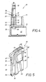
- a stop element 38 which here consists of an elastically molded button which, as illustrated in FIG. 4, produces an edge 39 which projects from the flat profile 48.
- control member 30 is pushed in by means of its handle 32 in the direction of the arrow 47 until, according to FIG. 4, the button 38 with its free button edge 39 abuts the upper end face 49 of the housing guide 46, which thus acts as a counter shoulder for the button 38 forms. 4, the key edge 39 can already engage with a tooth 59 in the guide 46 to ensure this stop action.
- control member 30 is provided with special control surfaces 50, which in the present case consist of a longitudinal groove running at an angle to the direction of movement 47, 47 'of the slide 30. These are assigned complementary counter surfaces 51 in the slide 12, which here consist of a longitudinal rib 51, which can be seen best from FIG.
- the complementary longitudinal ribs 51 are also arranged opposite one another in an opening 52 in the slide 12.
- This opening 52 is arranged in a continuation of the guide 46 located in the housing 11 and although it has an opening width 53 which is adapted to the control member flat profile 48 and can be seen in FIG. 2, it has an opening length 54 which exceeds the flat profile 48 39, 49 immersed depth 55 of the control member 30 in the housing 11, which can be seen from FIG. 1, the control surface 50 on the link 30 with the engagement area 56 shown in FIG. 1 already partially engages the counter surface 51 on the slide 12. This is one in the sense of the counter-arrow 14 'of FIG. 1, it is no longer possible to pull the slide 12 out of the housing 11.
- control member 30 projects with a section 60 from its guide 46 in the housing 11.
- This section 60 is an unmistakable signal that indicates the correct mounting position of the slide 12 in the housing 11. The fitter recognizes that he can now reliably perform the aforementioned assembly 45 of the individual contact members 20.
- the fitter can only move the control member 30 further in the direction of the further push-in arrow 57 in FIG. 3 if the stop action 39, 49 of the button 38 is eliminated. This is done, as can be seen from FIG. 4, by pressing the key 38 in the direction of the pivoting arrow 65 and pressing the key edge 39, which until then has been blocking, into the flat profile 48 of the control element, so that the entire key 38 with the inside width 66 of the key Housing guide 46 is aligned. The control member 30 can then be pressed into the structural unit comprising the housing 11 and the slide 12 up to the full immersion depth 55 '.
- This immersion depth 55 ' is limited in the insertion sense 57 by the abutment lugs 61 which can be seen in FIG. 5 abutting the end faces 49 of the control member guide 46 in the housing 11 in the area of its handle 32.
- the control surfaces 50 located on the control member 30 slide on the slide-side counter surfaces 51 and lead to the thrust movement illustrated by the arrow 15 'in FIG. 3. In terms of direction, this is opposite to the insertion movement 14 of the slide 12 described in connection with FIG. 1.
- control member 30 protrudes only by a small section 60 'according to FIG. 3 from the housing 11 and thus signals the completion of this particular thrust position of the slide 12, which for reasons to be explained in more detail below will be referred to briefly as the "locking position". Accordingly, this working position of the control member 30 is hereinafter referred to as the "locking position”.
- the locking position of the control member 30 which can be seen in FIG. 3 is, however, also secured against an unintentional pull-out movement in the direction of the arrow 57 ', because the above-mentioned upper latch 35 now interacts with a projection 63 provided in the guide 46 of the control member 30.
- the immersion depth 55 ' is thus fixed in both directions of movement 57, 57'.
- the locking position of the slider 12 is of course also precisely defined by means of the surfaces 50, 51 that have moved into one another. In this locking position, the previously assembled contact members 20 are captively fixed in the housing 11 and in the slide 12, which is accomplished in the following manner.
- the position of the contact members 20 in the coupling half 10 is thus fixed; the contact members can no longer be dismantled in the direction of the arrow 45 'of FIG. 3.
- This secured position of the contact members 20 in the coupling half 10 is signaled by the small projecting section 60 'of the control member 30. The fitter can be confident that the coupling half 10 is completed.
- the control member 30 To carry out the disassembly 45 ', the control member 30 must first be pulled out of its housing guide 46 in the direction of the outward arrow 57'. For this purpose, a certain amount of force is deliberately required in order to overcome the above-mentioned, engaged two locking element halves 35, 63. This extension movement 57 'is then again determined by the further locking element pair 34, 58 described in connection with FIG. 1. This is also audible to the fitter, because at the same time the elastic button 38 snaps out of the housing guide 46, which is pushed back into the flat profile 48 of the control member 30, into the position shown in FIG. 4.
- the two surfaces 50, 51 act again between the control member 30 and the slide 12 and provide the aforementioned pushing movement 15 of the slide 12 by the distance 44 mentioned.
- the contact members 20 are unlocked and can be pulled out of the two sections 23, 22 of the bores in the sense of the dismantling arrow 45 'of FIG. 1.
- the contact members 20 can be exchanged or corrected. Because the handle 32 protrudes around the mentioned section 60 ', the pull-out movement 57' of the control member 30 can be carried out conveniently and quickly.
- the handle 32 is provided with an opening 64 into which a tool, such as a screwdriver, is inserted and a lever movement on the control member 30 is permitted.
- the mounting position of the slider 12 shown in FIG. 1 could be secured instead of the stops 41, 42 there by holding elements (not shown) between the slider 12 and the housing 11, which are arranged in the region of the housing slot 13 and z . B. interact like a snap.
- the thrust direction 15 'of FIG. 3 could also be oriented in the same direction instead of in the opposite direction to the preceding insertion movement 14. After the insertion movement 14, the slide 12 would then be moved further into its locking position 15 'in the same direction.
Landscapes
- Details Of Connecting Devices For Male And Female Coupling (AREA)
- Coupling Device And Connection With Printed Circuit (AREA)
- Measurement And Recording Of Electrical Phenomena And Electrical Characteristics Of The Living Body (AREA)
- Connector Housings Or Holding Contact Members (AREA)
- Connections By Means Of Piercing Elements, Nuts, Or Screws (AREA)
Applications Claiming Priority (2)
| Application Number | Priority Date | Filing Date | Title |
|---|---|---|---|
| DE4029300A DE4029300C1 (en) | 1990-09-15 | 1990-09-15 | Multipole electrical connector - has crimped connectors forced against projections on housing to provide secure retention |
| DE4029300 | 1990-09-15 |
Publications (2)
| Publication Number | Publication Date |
|---|---|
| EP0477610A1 true EP0477610A1 (fr) | 1992-04-01 |
| EP0477610B1 EP0477610B1 (fr) | 1994-06-08 |
Family
ID=6414314
Family Applications (1)
| Application Number | Title | Priority Date | Filing Date |
|---|---|---|---|
| EP91114898A Expired - Lifetime EP0477610B1 (fr) | 1990-09-15 | 1991-09-04 | Eléments de couplage enfichables multipolaires pour conducteurs électriques |
Country Status (4)
| Country | Link |
|---|---|
| EP (1) | EP0477610B1 (fr) |
| AT (1) | ATE107082T1 (fr) |
| DE (2) | DE4029300C1 (fr) |
| ES (1) | ES2057686T3 (fr) |
Cited By (2)
| Publication number | Priority date | Publication date | Assignee | Title |
|---|---|---|---|---|
| EP0623973A1 (fr) * | 1993-05-07 | 1994-11-09 | Sumitomo Wiring Systems, Ltd. | Connecteur |
| WO2005107020A1 (fr) * | 2004-04-26 | 2005-11-10 | Valeo Electronique Et Systemes De Liaison | Elément de boîtier de connecteur électrique, organe de contact électrique destiné à équiper un tel boîtier et outil pour l'extraction desdits organes électriques. |
Families Citing this family (2)
| Publication number | Priority date | Publication date | Assignee | Title |
|---|---|---|---|---|
| DE4330359C2 (de) * | 1993-09-08 | 1995-06-14 | Reinshagen Kabelwerk Gmbh | Gedichteter elektrischer Steckverbinder |
| DE19730979B4 (de) * | 1997-07-18 | 2008-07-10 | The Whitaker Corp., Wilmington | Elektrischer Steckverbinder und Steckergehäuse dafür |
Citations (4)
| Publication number | Priority date | Publication date | Assignee | Title |
|---|---|---|---|---|
| DE2707122A1 (de) * | 1976-02-20 | 1977-09-01 | Japan Aviation Electron | Kontaktverbindungselement |
| DE3023313A1 (de) * | 1980-06-21 | 1982-01-07 | Robert Bosch Gmbh, 7000 Stuttgart | Vielpolige steckvorrichtung |
| EP0251518A2 (fr) * | 1986-06-21 | 1988-01-07 | LUCAS INDUSTRIES public limited company | Connecteurs électriques |
| DE3736036C1 (en) * | 1987-10-24 | 1989-02-02 | Kostal Leopold Gmbh & Co Kg | Electrical plug connector part |
Family Cites Families (2)
| Publication number | Priority date | Publication date | Assignee | Title |
|---|---|---|---|---|
| DE3441559A1 (de) * | 1984-11-14 | 1986-05-22 | Adam Opel AG, 6090 Rüsselsheim | Steckverbindung |
| DE3735205A1 (de) * | 1987-10-17 | 1989-04-27 | Reinshagen Kabelwerk Gmbh | Mehrpolige steckbare kupplungshaelfte fuer elektrische leitungen |
-
1990
- 1990-09-15 DE DE4029300A patent/DE4029300C1/de not_active Expired - Fee Related
-
1991
- 1991-09-04 AT AT91114898T patent/ATE107082T1/de not_active IP Right Cessation
- 1991-09-04 DE DE59101847T patent/DE59101847D1/de not_active Expired - Lifetime
- 1991-09-04 EP EP91114898A patent/EP0477610B1/fr not_active Expired - Lifetime
- 1991-09-04 ES ES91114898T patent/ES2057686T3/es not_active Expired - Lifetime
Patent Citations (4)
| Publication number | Priority date | Publication date | Assignee | Title |
|---|---|---|---|---|
| DE2707122A1 (de) * | 1976-02-20 | 1977-09-01 | Japan Aviation Electron | Kontaktverbindungselement |
| DE3023313A1 (de) * | 1980-06-21 | 1982-01-07 | Robert Bosch Gmbh, 7000 Stuttgart | Vielpolige steckvorrichtung |
| EP0251518A2 (fr) * | 1986-06-21 | 1988-01-07 | LUCAS INDUSTRIES public limited company | Connecteurs électriques |
| DE3736036C1 (en) * | 1987-10-24 | 1989-02-02 | Kostal Leopold Gmbh & Co Kg | Electrical plug connector part |
Cited By (3)
| Publication number | Priority date | Publication date | Assignee | Title |
|---|---|---|---|---|
| EP0623973A1 (fr) * | 1993-05-07 | 1994-11-09 | Sumitomo Wiring Systems, Ltd. | Connecteur |
| US5501619A (en) * | 1993-05-07 | 1996-03-26 | Sumitomo Wiring Systems, Ltd. | Connector |
| WO2005107020A1 (fr) * | 2004-04-26 | 2005-11-10 | Valeo Electronique Et Systemes De Liaison | Elément de boîtier de connecteur électrique, organe de contact électrique destiné à équiper un tel boîtier et outil pour l'extraction desdits organes électriques. |
Also Published As
| Publication number | Publication date |
|---|---|
| ATE107082T1 (de) | 1994-06-15 |
| DE4029300C1 (en) | 1992-03-12 |
| EP0477610B1 (fr) | 1994-06-08 |
| ES2057686T3 (es) | 1994-10-16 |
| DE59101847D1 (de) | 1994-07-14 |
Similar Documents
| Publication | Publication Date | Title |
|---|---|---|
| DE69311012T2 (de) | Elektrischer Verbinder | |
| DE102013015719B4 (de) | Hebeltypverbinder mit Ritzelzähnen und Verfahren zum Zusammenbauen desselben | |
| EP0273999B1 (fr) | Arrangement d'un connecteur à levier à crémaillère | |
| DE102004063236B4 (de) | Verbinder, welcher ein bewegbares Glied aufweist, und Verbinderanordnung | |
| EP0317755B1 (fr) | Partie de couplage multipolaire enfichable pour conducteurs électriques | |
| DE4239124A1 (fr) | ||
| EP0805366A1 (fr) | Connecteur | |
| DE69601885T2 (de) | Verriegelbarer Tastschalter | |
| EP3252884A1 (fr) | Prise de voyage compacte | |
| DE69838236T2 (de) | Ein Verbinder mit Verriegelung | |
| EP3316414A1 (fr) | Adaptateur de prise de courant de voyage pouvant être mis à la terre | |
| DE10006922A1 (de) | Steckeranordnung mit geringer Koppelkraft | |
| DE102004060637A1 (de) | Verbinder | |
| EP0477610B1 (fr) | Eléments de couplage enfichables multipolaires pour conducteurs électriques | |
| DE102004061888B4 (de) | Verbinder | |
| EP3459146B1 (fr) | Adaptateur électrique de voyage facile à utiliser | |
| DE19910027A1 (de) | Mit geringer Kraft kuppelbarer Steckverbinder | |
| DE2355656C2 (de) | Elektrische Steckverbindungsvorrichtung | |
| DE19532623B4 (de) | Elektrischer Stecker mit einem Betätigungsschieber | |
| DE4005136C2 (fr) | ||
| DE9014813U1 (de) | Mehrpolige steckbare Kupplungshälfte für elektrische Leitungen | |
| DE19917825C2 (de) | Steckverbinder mit einem hebelbetätigten Schiebermechanismus | |
| DE2741219B2 (de) | Schaltervorrichtung | |
| DE4439386C1 (de) | Elektrischer Verbindungsteil einer zweiteiligen Steckverbindung | |
| DE19530844A1 (de) | Elektrischer Stecker mit einem Betätigungsschieber |
Legal Events
| Date | Code | Title | Description |
|---|---|---|---|
| PUAI | Public reference made under article 153(3) epc to a published international application that has entered the european phase |
Free format text: ORIGINAL CODE: 0009012 |
|
| 17P | Request for examination filed |
Effective date: 19920206 |
|
| AK | Designated contracting states |
Kind code of ref document: A1 Designated state(s): AT BE DE ES FR GB IT SE |
|
| 17Q | First examination report despatched |
Effective date: 19931108 |
|
| GRAA | (expected) grant |
Free format text: ORIGINAL CODE: 0009210 |
|
| AK | Designated contracting states |
Kind code of ref document: B1 Designated state(s): AT BE DE ES FR GB IT SE |
|
| PG25 | Lapsed in a contracting state [announced via postgrant information from national office to epo] |
Ref country code: BE Effective date: 19940608 |
|
| REF | Corresponds to: |
Ref document number: 107082 Country of ref document: AT Date of ref document: 19940615 Kind code of ref document: T |
|
| ITF | It: translation for a ep patent filed | ||
| REF | Corresponds to: |
Ref document number: 59101847 Country of ref document: DE Date of ref document: 19940714 |
|
| GBT | Gb: translation of ep patent filed (gb section 77(6)(a)/1977) |
Effective date: 19940616 |
|
| PG25 | Lapsed in a contracting state [announced via postgrant information from national office to epo] |
Ref country code: AT Effective date: 19940904 |
|
| PG25 | Lapsed in a contracting state [announced via postgrant information from national office to epo] |
Ref country code: SE Effective date: 19940908 |
|
| ET | Fr: translation filed | ||
| REG | Reference to a national code |
Ref country code: ES Ref legal event code: FG2A Ref document number: 2057686 Country of ref document: ES Kind code of ref document: T3 |
|
| PLBE | No opposition filed within time limit |
Free format text: ORIGINAL CODE: 0009261 |
|
| STAA | Information on the status of an ep patent application or granted ep patent |
Free format text: STATUS: NO OPPOSITION FILED WITHIN TIME LIMIT |
|
| 26N | No opposition filed | ||
| REG | Reference to a national code |
Ref country code: FR Ref legal event code: CD |
|
| REG | Reference to a national code |
Ref country code: ES Ref legal event code: PC2A |
|
| REG | Reference to a national code |
Ref country code: GB Ref legal event code: IF02 |
|
| PGFP | Annual fee paid to national office [announced via postgrant information from national office to epo] |
Ref country code: GB Payment date: 20030911 Year of fee payment: 13 |
|
| PGFP | Annual fee paid to national office [announced via postgrant information from national office to epo] |
Ref country code: ES Payment date: 20030929 Year of fee payment: 13 |
|
| PG25 | Lapsed in a contracting state [announced via postgrant information from national office to epo] |
Ref country code: GB Free format text: LAPSE BECAUSE OF NON-PAYMENT OF DUE FEES Effective date: 20040904 |
|
| PG25 | Lapsed in a contracting state [announced via postgrant information from national office to epo] |
Ref country code: ES Free format text: LAPSE BECAUSE OF NON-PAYMENT OF DUE FEES Effective date: 20040906 |
|
| GBPC | Gb: european patent ceased through non-payment of renewal fee |
Effective date: 20040904 |
|
| REG | Reference to a national code |
Ref country code: ES Ref legal event code: FD2A Effective date: 20040906 |
|
| PGFP | Annual fee paid to national office [announced via postgrant information from national office to epo] |
Ref country code: FR Payment date: 20100921 Year of fee payment: 20 Ref country code: IT Payment date: 20100916 Year of fee payment: 20 |
|
| REG | Reference to a national code |
Ref country code: FR Ref legal event code: TP |
|
| PGFP | Annual fee paid to national office [announced via postgrant information from national office to epo] |
Ref country code: DE Payment date: 20100901 Year of fee payment: 20 |
|
| REG | Reference to a national code |
Ref country code: DE Ref legal event code: R081 Ref document number: 59101847 Country of ref document: DE Owner name: DELPHI TECHNOLOGIES, INC., TROY, US Free format text: FORMER OWNER: DELPHI AUTOMOTIVE SYSTEMS DEUTSCHLAND GMBH, 42369 WUPPERTAL, DE Effective date: 20110504 Ref country code: DE Ref legal event code: R081 Ref document number: 59101847 Country of ref document: DE Owner name: DELPHI TECHNOLOGIES, INC., US Free format text: FORMER OWNER: DELPHI AUTOMOTIVE SYSTEMS DEUTSCHLAND GMBH, 42369 WUPPERTAL, DE Effective date: 20110504 |
|
| REG | Reference to a national code |
Ref country code: DE Ref legal event code: R071 Ref document number: 59101847 Country of ref document: DE |
|
| REG | Reference to a national code |
Ref country code: DE Ref legal event code: R071 Ref document number: 59101847 Country of ref document: DE |
|
| PG25 | Lapsed in a contracting state [announced via postgrant information from national office to epo] |
Ref country code: DE Free format text: LAPSE BECAUSE OF EXPIRATION OF PROTECTION Effective date: 20110905 |