EP0477732B1 - Procédé et dispositif de meulage - Google Patents
Procédé et dispositif de meulage Download PDFInfo
- Publication number
- EP0477732B1 EP0477732B1 EP91115769A EP91115769A EP0477732B1 EP 0477732 B1 EP0477732 B1 EP 0477732B1 EP 91115769 A EP91115769 A EP 91115769A EP 91115769 A EP91115769 A EP 91115769A EP 0477732 B1 EP0477732 B1 EP 0477732B1
- Authority
- EP
- European Patent Office
- Prior art keywords
- grinding
- workpiece
- parallel
- cylinder
- shoulder
- Prior art date
- Legal status (The legal status is an assumption and is not a legal conclusion. Google has not performed a legal analysis and makes no representation as to the accuracy of the status listed.)
- Expired - Lifetime
Links
- 238000000034 method Methods 0.000 title claims description 13
- 238000003754 machining Methods 0.000 description 8
- 239000006061 abrasive grain Substances 0.000 description 2
- 229910052582 BN Inorganic materials 0.000 description 1
- PZNSFCLAULLKQX-UHFFFAOYSA-N Boron nitride Chemical compound N#B PZNSFCLAULLKQX-UHFFFAOYSA-N 0.000 description 1
- 238000010586 diagram Methods 0.000 description 1
- 239000002184 metal Substances 0.000 description 1
- 238000012986 modification Methods 0.000 description 1
- 230000004048 modification Effects 0.000 description 1
- 230000002093 peripheral effect Effects 0.000 description 1
- 230000002265 prevention Effects 0.000 description 1
- 238000004904 shortening Methods 0.000 description 1
Images



Classifications
-
- B—PERFORMING OPERATIONS; TRANSPORTING
- B24—GRINDING; POLISHING
- B24B—MACHINES, DEVICES, OR PROCESSES FOR GRINDING OR POLISHING; DRESSING OR CONDITIONING OF ABRADING SURFACES; FEEDING OF GRINDING, POLISHING, OR LAPPING AGENTS
- B24B5/00—Machines or devices designed for grinding surfaces of revolution on work, including those which also grind adjacent plane surfaces; Accessories therefor
- B24B5/02—Machines or devices designed for grinding surfaces of revolution on work, including those which also grind adjacent plane surfaces; Accessories therefor involving centres or chucks for holding work
- B24B5/04—Machines or devices designed for grinding surfaces of revolution on work, including those which also grind adjacent plane surfaces; Accessories therefor involving centres or chucks for holding work for grinding cylindrical surfaces externally
Definitions
- the present invention relates to a method and a machine for grinding a cylindrical surface and an end surface perpendicular thereto of a rotating workpiece (see DE-C-38 17 453).
- a conventional angular grinding wheel is shown in Fig. 1, where a workpiece W has a cylindrical surface and a shoulder portion to be ground.
- the grinding wheel has a cylinder-grinding surface 1 and a shoulder-grinding surface 2 perpendicular to the cylinder-grinding surface 1 whose generatrix is parallel to the generatrix of the cylindrical surface to be ground.
- the shoulder-grinding surface 2 grinds the shoulder portion of the workpiece.
- the wheel is moved toward the central line of the workpiece W in a direction intersecting the cylindrical surface so that the wheel may be fed into the workpiece. Then, the wheel is moved relative to the workpiece along the generatrix of the cylindrical surface.
- the cylindrical surface of the workpiece W is machined with the cylinder-grinding surface 1 of the angular grinding wheel by traverse grinding.
- the DE-C-38 17 453 discloses a method and an apparatus for grinding cylindrical surfaces of workpieces with a circular grinding wheel, whereby a cylindrical surface is ground first by a cylinder-grinding tilted surface and then by a cylinder-grinding parallel surface.
- this document shows an end surface grinding wherein a lateral surface of a grinding wheel is used to grind an end surface of a workpiece flange portion.
- the before-mentioned objects are achieved by a method comprising the features of claim 1 and by a machine comprising the features of claim 4.
- the tilted grinding surface makes no local contact with the cylindrical surface of the workpiece. Hence, the grinding wheel is prevented from wearing down locally too quickly.
- the parallel grinding surface continuous with the tilted grinding surface performs a finishing grinding operation on the cylindrical surface. In consequence, no separate finishing grinding operation is needed. Also, the machining efficiency can be enhanced.
- a grinding machine comprises a circular grinding wheel having a parallel grinding surface and a tilted grinding surface continuous with the parallel grinding surface.
- This parallel grinding surface has a generatrix parallel to the generatrix of a cylindrical surface to be ground.
- the tilted grinding surface has a generatrix tilted away from the generatrix of the cylindrical surface.
- a control means causes the grinding wheel to move relative to the workpiece into the cylindrical surface. The wheel is fed into the cylindrical surface to a depth corresponding to the grinding allowance. Then, the cylindrical surface is ground by the tilted grinding surface. Subsequently, the grinding wheel is moved relative to the workpiece along the generatrix of the cylindrical surface in such a direction that the cylindrical surface is ground by the parallel grinding surface. In this way, the above-described objects of the invention are achieved.
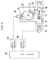
- a CNC grinding machine according to the invention.
- This machine has a bed 10 on which a wheel spindle stock 12 and a work table 11 are guided so as to be movable in the directions of X- and Y-axes, respectively, which are perpendicular to each other.
- a wheel spindle is held to the spindle stock 12 so as to be rotatable about an axis which is inclined at a given angle ⁇ to the axis of rotation of a cylindrical workpiece W (described later) within a horizontal plane.
- An angular grinding wheel G is mounted to one end of the wheel spindle and driven by an electric motor (not shown).
- This grinding wheel G comprises a metallic disk and a layer of abrasive grains of CBN (cubic system of boron nitride) formed on the outer periphery of the disk.
- the abrasive grains are bonded together with a metal bond.
- This wheel G is narrower than the conventional grinding wheel.
- a headstock 17 and a tailstock 18 are disposed opposite to each other on the table 11.
- the workpiece W is held by the headstock 17 and the tailstock 18 in such a way that the workpiece can rotate about an axis parallel to the direction of the Z-axis in which the table 11 is moved.
- the workpiece W is rotated by a spindle motor (not shown).
- Feed screws 14 and 13 are screwed to the spindle stock 12 and the table 11, respectively. These screws 13 and 14 are rotated by servomotors 15 and 16, respectively.
- the servomotors 15 and 16 are connected with drive circuits 28 and 27, respectively, and are controlled by instruction pulses supplied from a control unit 20 that is connected with the drive circuits 27, 28 to provide a numerical control of the servomotors.
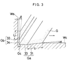
- Fig. 3 is an enlarged view of the angular grinding wheel G, for showing its shape.
- the workpiece W has a cylindrical surface Wc.
- a cylinder-grinding surface Ga for grinding the cylindrical surface Wc and a shoulder-grinding surface Gb are formed on the grinding wheel G.
- the shoulder-grinding surface Gb acts to grind the end surface of the shoulder portion adjacent to the cylindrical surface Wc.
- An arc-shaped apical portion Gc having a given radius is formed between the cylinder-grinding surface Ga and the shoulder-grinding surface Gb.
- the cylinder-grinding surface Ga is composed of a cylinder-grinding tilted surface 31 and a cylinder-grinding parallel surface 33 formed between the tilted surface 31 and the apical portion Gc.
- This tilted surface 31 is a truncated conical surface which continues to the cylinder-grinding parallel surface 33 at the end on the side of the apical portion Gc.
- the distance between the truncated conical surface and the generatrix of the cylindrical surface Wc increases in going away from the cylinder-grinding parallel surface 33.
- the conical surface is tilted at angle ⁇ to the cylindrical surface Wc.
- the shoulder-grinding surface Gb comprises a shoulder-grinding tilted surface 32 and a shoulder-grinding parallel surface 34 formed between the tilted surface 32 and the apical portion Gc.
- This tilted surface 32 is a truncated conical surface which continues to the shoulder-grinding parallel surface 34 at the end on the side of the apical portion Gc. The distance between this conical surface and the end surface Ws of the shoulder portion of the workpiece increases in going away from the shoulder-grinding parallel surface 34.
- This conical surface is inclined at angle ⁇ to the end surface Ws of the shoulder portion.
- the generatrix of the cylinder-grinding tilted surface 31 is inclined at the preset angle ⁇ in the direction to move away from the generatrix of the cylindrical surface Wc of the workpiece W.
- the generatrix of the shoulder-grinding tilted surface 32 is inclined at the preset angle ⁇ in the direction to move away from the end surface Ws of the shoulder portion of the workpiece W.
- L1 and L2 be the cross-sectional lengths of the cylinder-grinding tilted surface 31 and the shoulder-grinding tilted surface 32, respectively.
- the angles ⁇ and ⁇ are so set that L1sin ⁇ and L2sin ⁇ correspond to the finishing grinding allowances for the cylindrical surface Wc and the end surface Ws of the shoulder portion, respectively.
- the cylinder-grinding parallel surface 33 and the shoulder-grinding parallel surface 34 are parallel to the cylindrical surface Wc and the end surface Ws of the shoulder portion, respectively, at the grinding point. Since the diameter of the grinding wheel is large, the cylinder-grinding parallel surface 33 has a larger peripheral speed and experiences less resistance compared with the cylinder-grinding tilted surface 31. Therefore, during grinding operation, the workpiece W flexes only a little.
- the cylinder-grinding parallel surface 33 functions well as a finishing grinding portion for the cylindrical surface Wc of the workpiece W.
- the shoulder-grinding parallel surface 34 functions well as a finishing grinding portion for the end surface Ws of the shoulder portion of the workpiece W.
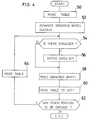
- Fig. 4 is a flowchart illustrating the operation of the control unit 20.
- the table 11 is moved in the direction of the Z-axis (step 50).
- the first cylindrical surface W1 is placed at the machining position.
- the table 11 is moved to the right and, at the same time, the spindle stock 12 is advanced to quickly place the grinding wheel G at the position corresponding to the end of the first cylindrical surface Wc1 close to the end surface Ws of the shoulder portion.
- step 52 A decision is made to determine whether there exists a shoulder portion end surface which is adjacent to the cylindrical surface Wc1 and should be machined (step 54).
- step 56 is skipped, and control goes to step 58.
- step 56 the table 11 is first moved to the right over a given distance at a given infeed speed.
- the shoulder-grinding surface Gb of the grinding wheel G is fed into the end surface W2 of the shoulder portion by a given grinding allowance.
- the spindle stock 12 is moved backward at a given grinding speed.
- the end surface Ws of the shoulder portion of the workpiece W is first ground by the shoulder-grinding tilted surface 32.
- a finishing grinding operation is performed by the shoulder-grinding parallel surface 34.
- the table 11 is moved to the left over a given distance to form a certain clearance between the grinding wheel G and the end surface Ws of the shoulder portion.
- the spindle stock 12 is advanced again at a high speed back into its original radial position.
- the spindle stock 12 is fed into the workpiece W toward the axis of rotation of the workpiece to feed the wheel into the first cylindrical surface Wc1 to a given depth corresponding to the grinding allowance (step 58).
- the table 11 is moved to the left.
- the first cylindrical surface Wc1 of the workpiece W is first roughly ground by the cylinder-grinding tilted surface 31.
- the cylinder-grinding parallel surface 33 performs a finishing grinding operation (step 60).
- the cylindrical surface Wc is ground by the whole of the cylinder-grinding tilted surface 31 and, therefore, excessive local wear of the angular grinding wheel G is prevented.
- the machining of the cylindrical surface Wc1 is completed by a single traverse grinding operation, because a finishing grinding operation is carried out by the cylinder-grinding parallel surface 33 after the cylindrical surface Wc1 is roughly ground by the cylinder-grinding tilted surface 31. Consequently, the grinding time can be shortened.
- step 62 a decision is made to determine whether there exists any other portion to be ground. If not so, the grinding process is ended. On the other hand, if the result of the decision is that there exists any portion to be ground other than the first cylindrical surface as in the present example, then control goes to step 64, where the next second cylindrical surface Wc2 is brought into the machining position. The grinding wheel G is placed at the left end of the second cylindrical surface Wc2. Subsequently, the processing beginning with step 54 is performed again to machine the second cylindrical surface Wc2. The third machined surface Wc3 is machined in the same way.
- the present invention is also applicable to the case in which a taper is ground on a workpiece.
- the table is inclined in such a way that the generatrix of the tapering cylindrical surface is parallel to the direction of movement of the table at the machining position. Under this condition, the taper is ground.
- an angular grinding wheel is used.
- a grinding wheel having only an outer surface parallel to the axis of rotation of the workpiece may also be employed.
- this outer surface has a grinding parallel surface 33 and a grinding tilted surface 31.
- the parallel surface 33 has a generatrix parallel to the generatrix of the cylindrical surface to be ground.
- the tilted surface 31 is continuous with the parallel surface 33 and has a generatrix inclined away from the generatrix of the cylindrical surface.
Landscapes
- Engineering & Computer Science (AREA)
- Mechanical Engineering (AREA)
- Grinding Of Cylindrical And Plane Surfaces (AREA)
Claims (6)
- Procédé de meulage d'une surface cylindrique (Wc) et d'une surface d'extrémité (Ws) perpendiculaire à cette dernière d'une pièce à usiner tournante (W) respectivement avec une première et une deuxième surfaces (Ga, Gb) de meulage d'une meule rotative (G), comprenant les étapes consistant à former la première surface de meulage (Ga) avec une surface parallèle de meulage de cylindre (33) qui s'étend parallèlement à la génératrice de la surface cylindrique (Wc) et perpendiculairement à la surface d'extrémité (Ws) et avec une surface inclinée de meulage de cylindre (31) qui s'étend de manière contigüe à la surface parallèle de meulage de cylindre (33) et est décalée par rapport à la génératrice de la surface cylindrique (Wc) dans le sens radial de la pièce à usiner (W) alors qu'elle s'éloigne à partir de la deuxième surface de meulage (Gb) dans le sens axial de la pièce à usiner (W) ; et à effectuer des mouvements relatifs entre la meule (G) et la pièce à usiner (W) dans le sens axial de la pièce à usiner (W) de sorte que la surface inclinée de meulage de cylindre (31) meule d'abord grossièrement la surface cylindrique (Wc) alors que la surface parallèle de meulage de cylindre (33) meule finement la partie grossièrement meulée de la surface cylindrique (Wc),
caractérisé en ce qu'il
comprend, en outre, les étapes consistant à former la deuxième surface de meulage (Gb) non seulement avec une surface parallèle de meulage d'épaulement (34) qui s'étend de manière contigüe et perpendiculaire à la surface parallèle de meulage de cylindre (33), mais également avec une surface inclinée de meulage d'épaulement (32), qui s'étend de manière contigüe à la surface parallèle de meulage d'épaulement (34) et est décalée par rapport à cette dernière dans le sens axial de la pièce à usiner (W) alors qu'elle s'éloigne dans le sens radial de la pièce à usiner (W) ; et à meuler la surface d'extrémité (Ws) de la pièce à usiner (G), plaçant d'abord la deuxième surface de meulage (Gb) en prise avec une partie interne dans le sens radial de la surface d'extrémité (Ws), puis, en éloignant la meule (G) de la pièce à usiner (W) dans le sens radial de la pièce à usiner (W) de sorte que la surface inclinée de meulage d'épaulement (32) meule d'abord grossièrement la surface d'extrémité (Ws) alors que la surface parallèle de meulage d'épaulement (34) meule finement la partie meulée de la surface d'extrémité (Ws). - Procédé selon la revendication 1, caractérisé en ce qu'il comprend en outre l'étape consistant à régler la meule (G) de manière à incliner l'axe de rotation de cette dernière selon un angle donné par rapport à l'axe de rotation de la pièce à usiner (W) de sorte que toutes les surfaces parallèle et inclinée de meulage de cylindre (33, 31) et les surfaces parallèle et inclinée de meulage d'épaulement (34, 32), sont présentées sur une surface circonférentielle de la meule (G), la surface parallèle de meulage de cylindre (33) et la surface parallèle de meulage d'épaulement (34) s'étendant respectivement parallèlement aux surfaces cylindrique et d'extrémité (Wc, Ws) de la pièce à usiner (W).
- Procédé selon la revendication 2, dans lequel la surface inclinée de meulage de cylindre (31) présente à sa jonction avec une surface latérale de la meule (G) une première valeur maximale de décalage par rapport à la surface parallèle de meulage de cylindre (33) et dans lequel la surface inclinée de meulage d'épaulement (32) présente à sa jonction avec l'autre surface de la meule (G) une deuxième valeur maximale de décalage par rapport à la surface parallèle de meulage d'épaulement (34), caractérisé en ce qu'il comprend en outre l'étape consistant à faire coïncider au moins une de la première et de la deuxième valeurs maximales de décalage avec une surépaisseur de meulage sur une des surfaces cylindrique et d'extrémité (Wc, Ws) correspondante de la pièce à usiner (W).
- Machine de meulage d'une surface cylindrique (Wc) et d'une surface d'extrémité (Ws) perpendiculaire à cette dernière d'une pièce à usiner tournante (W), comprenant:
des moyens de support de la pièce à usiner (11, 17, 18) pour supporter la pièce à usiner tournante (W);
une meule (G) présentant une première et deuxième surfaces de meulage (Ga, Gb) dans laquelle la première surface de meulage (Ga) pour le meulage de la surface cylindrique (Wc) de la pièce à usiner (G) comprend, outre une surface parallèle de meulage de cylindre (33) s'étendant parallèlement à la génératrice de la surface cylindrique (Wc) et perpendiculairement à la surface d'extrémité (Ws), une surface inclinée de meulage de cylindre (31) contigüe à la surface parallèle de meulage de cylindre (33) et décalée par rapport à la génératrice de la surface cylindrique (Wc) dans le sens radial de la pièce à usiner (W) alors qu'elle s'éloigne de la deuxième surface de meulage (Gb) dans le sens axial de la pièce à usiner;
des moyens de support de la meule (12) pour soutenir la meule rotative (G), la surface parallèle de meulage de cylindre (33) étant placée parallèlement à la génératrice de la surface cylindrique (Wc);
des moyens d'avance (15, 16) pour générer un mouvement relatif entre les moyens de support de la pièce à usiner (11, 17, 18) et les moyens de support de la meule (12) dans les sens radial et axial de la pièce à usiner (W); et
des moyens de commande (20, 27, 28) pour commander les moyens d'avance (15, 16), de sorte que dans un meulage transversal de la surface cylindrique (Wc) de la pièce à usiner (W), la surface inclinée de meulage de cylindre (31) meule d'abord grossièrement la surface cylindrique (Wc) alors que la surface parallèle de meulage de cylindre (33) meule finement la partie meulée grossièrement de la surface cylindrique (Wc); caractérisés en ce que:
la deuxième surface de meulage (Gb) est formée non seulement d'une surface parallèle de meulage d'épaulement (34) s'étendant de manière contigüe et perpendiculaire à la surface parallèle de meulage de cylindre (33) mais également d'une surface inclinée de meulage d'épaulement (32) contigüe à la surface parallèle de meulage d'épaulement (34) et décalée par rapport à cette dernière dans le sens axial de la pièce à usiner (W) alors qu'elle s'éloigne dans le sens radial de la pièce à usiner (W); et
les moyens de commande (20, 27, 28), lors du meulage de la surface d'extrémité (Ws) de la pièce à usiner (G), commandent les moyens d'avance (15, 16), de sorte que la deuxième surface de meulage (Gb) est d'abord mise en prise avec une partie interne dans le sens radial de la surface d'extrémité (Gb) puis est déplacée dans un sens relativement radial vers l'extérieur de la pièce à usiner (W), de sorte que la surface inclinée de meulage d'épaulement (32) meule grossièrement la surface d'extrémité (Ws) alors que la surface parallèle de meulage d'épaulement (34) meule finement la partie meulée de la surface d'extrémité (Ws). - Machine selon la revendication 4, caractérisée en ce qu'un axe autour duquel la meule (G) tourne s'étend en position inclinée selon un angle donné par rapport à l'axe de rotation de la pièce à usiner (W) de sorte que les surfaces parallèle et inclinée (33, 31) de meulage de cylindre et les surfaces parallèle et inclinée (34, 32) de meulage d'épaulement sont formées sur une surface circonférentielle de la meule (G).
- Machine selon la revendication 5, caractérisée en ce qu'un angle (a) selon lequel la surface inclinée de meulage de cylindre (31) est décalée par rapport à la surface parallèle de meulage de cylindre (33) est déterminé de telle sorte qu'une première valeur maximale de décalage est fournie à la jonction avec une surface latérale de la meule (G), alors qu'un autre angle (β) selon lequel la surface inclinée de meulage d'épaulement (32) est décalée par rapport à la surface parallèle de meulage d'épaulement (34) est déterminé de telle sorte qu'une deuxième valeur maximale de décalage est fournie à la jonction avec l'autre surface latérale de la meule (G); et en ce qu'au moins une de la première et deuxième valeurs de décalage coïncide avec une surépaisseur de meulage sur une des surfaces cylindrique et d'extrémité correspondante (Wc, Ws) de la pièce à usiner (W).
Applications Claiming Priority (2)
| Application Number | Priority Date | Filing Date | Title |
|---|---|---|---|
| JP2262265A JPH04141355A (ja) | 1990-09-28 | 1990-09-28 | 研削方法 |
| JP262265/90 | 1990-09-28 |
Publications (2)
| Publication Number | Publication Date |
|---|---|
| EP0477732A1 EP0477732A1 (fr) | 1992-04-01 |
| EP0477732B1 true EP0477732B1 (fr) | 1995-01-11 |
Family
ID=17373388
Family Applications (1)
| Application Number | Title | Priority Date | Filing Date |
|---|---|---|---|
| EP91115769A Expired - Lifetime EP0477732B1 (fr) | 1990-09-28 | 1991-09-17 | Procédé et dispositif de meulage |
Country Status (4)
| Country | Link |
|---|---|
| US (1) | US5228241A (fr) |
| EP (1) | EP0477732B1 (fr) |
| JP (1) | JPH04141355A (fr) |
| DE (1) | DE69106644D1 (fr) |
Families Citing this family (7)
| Publication number | Priority date | Publication date | Assignee | Title |
|---|---|---|---|---|
| EP0590640B1 (fr) * | 1992-09-30 | 1997-08-06 | Toyoda Koki Kabushiki Kaisha | Procédé et appareil pour meulage d'une pièce |
| US7021990B2 (en) * | 2003-08-19 | 2006-04-04 | Htt Hauser Tripet Tschudin Ag | Method and apparatus for circular grinding |
| US7029366B2 (en) * | 2004-08-17 | 2006-04-18 | Htt Hauser Tripet Tschudin Ag | Method and apparatus for abrasive circular machining |
| DE102010026026B4 (de) | 2010-07-03 | 2019-01-03 | Emag Holding Gmbh | Verfahren und Schleifmaschine zum Schleifen von Rotationsflächen |
| CN103659493B (zh) * | 2012-08-31 | 2015-11-11 | 自贡硬质合金有限责任公司 | 台阶套类零件的端面外圆加工方法 |
| DE102018130657A1 (de) * | 2017-12-14 | 2019-06-19 | Schaeffler Technologies AG & Co. KG | Verfahren zum Schleifen von Wälzkörpern für ein Wälzlager sowie Verwendung eines Verfahrens |
| US12017329B2 (en) * | 2019-12-20 | 2024-06-25 | Charles Neff | Grinding wheel with different work surfaces |
Family Cites Families (10)
| Publication number | Priority date | Publication date | Assignee | Title |
|---|---|---|---|---|
| ZA713105B (en) * | 1971-05-12 | 1972-09-27 | De Beers Ind Diamond | Diamond and the like grinding wheels |
| GB2067937A (en) * | 1980-01-19 | 1981-08-05 | Ti Matrix Ltd | Cylindrical grinding machine |
| DE3136441C2 (de) * | 1981-09-14 | 1986-06-26 | Fortuna-Werke Maschinenfabrik Gmbh, 7000 Stuttgart | Vorrichtung zum Rundschleifen von Werkstücken |
| JPS6279954A (ja) * | 1985-10-03 | 1987-04-13 | Daido Steel Co Ltd | 研削方法 |
| JPH0675818B2 (ja) * | 1986-03-28 | 1994-09-28 | 豊田工機株式会社 | アンギユラ研削盤 |
| SU1565666A1 (ru) * | 1987-10-01 | 1990-05-23 | Производственное объединение "Уралмаш" | Способ шлифовани |
| DE3737641A1 (de) * | 1987-10-19 | 1989-04-27 | Fortuna Werke Maschf Ag | Verfahren zum aussenrundschleifen von werkstuecken |
| DE3811584A1 (de) * | 1988-04-07 | 1989-10-19 | Winter & Sohn Ernst | Schleifscheibe zum tiefschleifen |
| DE3817453C1 (en) * | 1988-05-21 | 1989-11-16 | Fortuna-Werke Maschinenfabrik Gmbh, 7000 Stuttgart, De | method and apparatus for the cylindrical-surface grinding of workpieces, in particular the rough-grinding thereof |
| IT1232139B (it) * | 1989-07-07 | 1992-01-23 | Tacchella Macchine Spa | Macchina rettificatrice |
-
1990
- 1990-09-28 JP JP2262265A patent/JPH04141355A/ja active Pending
-
1991
- 1991-09-17 EP EP91115769A patent/EP0477732B1/fr not_active Expired - Lifetime
- 1991-09-17 DE DE69106644T patent/DE69106644D1/de not_active Expired - Lifetime
- 1991-09-17 US US07/760,931 patent/US5228241A/en not_active Expired - Lifetime
Also Published As
| Publication number | Publication date |
|---|---|
| US5228241A (en) | 1993-07-20 |
| EP0477732A1 (fr) | 1992-04-01 |
| JPH04141355A (ja) | 1992-05-14 |
| DE69106644D1 (de) | 1995-02-23 |
Similar Documents
| Publication | Publication Date | Title |
|---|---|---|
| US8500518B2 (en) | Method of grinding an indexable insert and grinding wheel for carrying out the grinding method | |
| US5899797A (en) | Method and apparatus for grinding cams with concave sides | |
| US5533931A (en) | Method and machine for grinding a workpiece | |
| US4942695A (en) | Method for cylindrical surface grinding of workspaces | |
| EP0477732B1 (fr) | Procédé et dispositif de meulage | |
| EP1330339B1 (fr) | Procede et appareil permettant de fabriquer un outil de coupe possedant une pluralite de listels | |
| US4866887A (en) | Method of truing grinding wheel | |
| JP3870000B2 (ja) | センタレス研削方法および研削装置 | |
| US10099342B2 (en) | Truer, truing apparatus including truer, grinder, and truing method | |
| JPH06134668A (ja) | 研削盤 | |
| JPS6411422B2 (fr) | ||
| JPH0899257A (ja) | 研削装置 | |
| JP4482632B2 (ja) | 端面スラスト研削の多段送り研削加工方法 | |
| JP3127493B2 (ja) | 砥石の修正方法 | |
| JP3322127B2 (ja) | 縦型nc研削盤 | |
| JPS62282852A (ja) | 研削加工方法 | |
| JP3723628B2 (ja) | コンタリング研削用砥石およびコンタリング研削方法 | |
| JPH04240061A (ja) | 小径穴の内面加工方法およびその装置 | |
| JPH0413085Y2 (fr) | ||
| MXPA01000065A (en) | Method for grinding at least one surface on a cutting knife used in machining, use of said method and grinding wheel used to carry out said method | |
| Hahn | Part Processing by Grinding | |
| JPH01271172A (ja) | Nc平面研削盤 | |
| JP2010052071A (ja) | 砥石のツルーイング方法および研削加工方法 | |
| JPH03196902A (ja) | 工具研削装置付旋盤 | |
| JPS62193756A (ja) | 研削盤 |
Legal Events
| Date | Code | Title | Description |
|---|---|---|---|
| PUAI | Public reference made under article 153(3) epc to a published international application that has entered the european phase |
Free format text: ORIGINAL CODE: 0009012 |
|
| AK | Designated contracting states |
Kind code of ref document: A1 Designated state(s): DE FR GB |
|
| 17P | Request for examination filed |
Effective date: 19920930 |
|
| 17Q | First examination report despatched |
Effective date: 19930614 |
|
| GRAA | (expected) grant |
Free format text: ORIGINAL CODE: 0009210 |
|
| AK | Designated contracting states |
Kind code of ref document: B1 Designated state(s): DE FR GB |
|
| PG25 | Lapsed in a contracting state [announced via postgrant information from national office to epo] |
Ref country code: FR Effective date: 19950111 |
|
| REF | Corresponds to: |
Ref document number: 69106644 Country of ref document: DE Date of ref document: 19950223 |
|
| PG25 | Lapsed in a contracting state [announced via postgrant information from national office to epo] |
Ref country code: DE Effective date: 19950412 |
|
| EN | Fr: translation not filed | ||
| PGFP | Annual fee paid to national office [announced via postgrant information from national office to epo] |
Ref country code: GB Payment date: 19950908 Year of fee payment: 5 |
|
| PLBE | No opposition filed within time limit |
Free format text: ORIGINAL CODE: 0009261 |
|
| STAA | Information on the status of an ep patent application or granted ep patent |
Free format text: STATUS: NO OPPOSITION FILED WITHIN TIME LIMIT |
|
| 26N | No opposition filed | ||
| PG25 | Lapsed in a contracting state [announced via postgrant information from national office to epo] |
Ref country code: GB Effective date: 19960917 |
|
| GBPC | Gb: european patent ceased through non-payment of renewal fee |
Effective date: 19960917 |