EP0477745A1 - Messeinrichtung mit überlaufmessschwelle - Google Patents
Messeinrichtung mit überlaufmessschwelle Download PDFInfo
- Publication number
- EP0477745A1 EP0477745A1 EP91115806A EP91115806A EP0477745A1 EP 0477745 A1 EP0477745 A1 EP 0477745A1 EP 91115806 A EP91115806 A EP 91115806A EP 91115806 A EP91115806 A EP 91115806A EP 0477745 A1 EP0477745 A1 EP 0477745A1
- Authority
- EP
- European Patent Office
- Prior art keywords
- overflow
- crown
- weir
- overflow threshold
- standard profile
- Prior art date
- Legal status (The legal status is an assumption and is not a legal conclusion. Google has not performed a legal analysis and makes no representation as to the accuracy of the status listed.)
- Granted
Links
- 238000005259 measurement Methods 0.000 title claims description 18
- 239000007788 liquid Substances 0.000 claims abstract description 3
- XLYOFNOQVPJJNP-UHFFFAOYSA-N water Substances O XLYOFNOQVPJJNP-UHFFFAOYSA-N 0.000 claims description 23
- 230000001419 dependent effect Effects 0.000 claims description 6
- 230000001133 acceleration Effects 0.000 claims description 4
- 230000005484 gravity Effects 0.000 claims description 3
- 230000007704 transition Effects 0.000 claims description 3
- 238000011144 upstream manufacturing Methods 0.000 claims 1
- 238000013461 design Methods 0.000 description 15
- 230000015572 biosynthetic process Effects 0.000 description 2
- 239000011152 fibreglass Substances 0.000 description 2
- 230000001965 increasing effect Effects 0.000 description 2
- 230000001939 inductive effect Effects 0.000 description 2
- 238000004088 simulation Methods 0.000 description 2
- 210000002023 somite Anatomy 0.000 description 2
- 239000003643 water by type Substances 0.000 description 2
- 238000012935 Averaging Methods 0.000 description 1
- 241001669679 Eleotris Species 0.000 description 1
- 238000009825 accumulation Methods 0.000 description 1
- 230000009286 beneficial effect Effects 0.000 description 1
- 230000005540 biological transmission Effects 0.000 description 1
- 238000010276 construction Methods 0.000 description 1
- 238000001514 detection method Methods 0.000 description 1
- 238000011161 development Methods 0.000 description 1
- 238000009826 distribution Methods 0.000 description 1
- 238000009776 industrial production Methods 0.000 description 1
- 238000011545 laboratory measurement Methods 0.000 description 1
- 238000004519 manufacturing process Methods 0.000 description 1
- 239000004033 plastic Substances 0.000 description 1
- 229920003023 plastic Polymers 0.000 description 1
- 238000000926 separation method Methods 0.000 description 1
- 239000010865 sewage Substances 0.000 description 1
- 238000003860 storage Methods 0.000 description 1
- 238000009423 ventilation Methods 0.000 description 1
- 238000012795 verification Methods 0.000 description 1
Images


Classifications
-
- E—FIXED CONSTRUCTIONS
- E03—WATER SUPPLY; SEWERAGE
- E03F—SEWERS; CESSPOOLS
- E03F5/00—Sewerage structures
- E03F5/12—Emergency outlets
-
- E—FIXED CONSTRUCTIONS
- E02—HYDRAULIC ENGINEERING; FOUNDATIONS; SOIL SHIFTING
- E02B—HYDRAULIC ENGINEERING
- E02B8/00—Details of barrages or weirs ; Energy dissipating devices carried by lock or dry-dock gates
- E02B8/06—Spillways; Devices for dissipation of energy, e.g. for reducing eddies also for lock or dry-dock gates
-
- E—FIXED CONSTRUCTIONS
- E03—WATER SUPPLY; SEWERAGE
- E03F—SEWERS; CESSPOOLS
- E03F5/00—Sewerage structures
- E03F5/10—Collecting-tanks; Equalising-tanks for regulating the run-off; Laying-up basins
- E03F5/105—Accessories, e.g. flow regulators or cleaning devices
-
- G—PHYSICS
- G01—MEASURING; TESTING
- G01F—MEASURING VOLUME, VOLUME FLOW, MASS FLOW OR LIQUID LEVEL; METERING BY VOLUME
- G01F1/00—Measuring the volume flow or mass flow of fluid or fluent solid material wherein the fluid passes through a meter in a continuous flow
- G01F1/002—Measuring the volume flow or mass flow of fluid or fluent solid material wherein the fluid passes through a meter in a continuous flow wherein the flow is in an open channel
Definitions
- the invention relates to an overflow threshold for an overflow measurement dependent on the height of a liquid level.
- Rainwater overflow basins are increasingly being built and operated in mixed water drainage systems.
- the aim of this measure is to limit the runoff, for example to sewage treatment plants, by rainwater treatment in such a way that its efficiency does not drop inadmissibly and at the same time that intermittent pollution of receiving waters, for example rivers and waters, remains within reasonable limits.
- the requirements of the supervisory authorities of individual countries therefore require (already with the building permit) pools and rain overflows to be equipped with measuring devices in order to enable the annual discharge amount to be recorded.
- measurement data acquisition for verification purposes should also be set up at rain overflow basins and possibly also at exposed rain overflows.
- overflow thresholds at which a water level measurement is carried out on the upper water side.
- the height of the water level above the crown of the overflow threshold is measured and the overflow quantity is determined from this measured variable.
- This height-dependent overflow measurement is particularly economical, but in the known devices it is subject to a variety of measurement errors.
- inductive flow meters can also be used for the relief measurement. These inductive flowmeters are undoubtedly the smallest measuring errors.
- this measuring device In the relief line, which is usually designed as a free-mirror line, this measuring device must then be used in conjunction with a dimmed measuring tube, because proper operation is only achieved when the measuring tube is full.
- Such measuring structures require extremely high investment costs, so that, as a rule, it must be avoided for economic reasons. This solution is only reserved for exceptional operating points.
- the invention is concerned with the height-dependent overflow measurement.
- the object of the invention is therefore to provide an overflow threshold or a measuring device with an overflow threshold, which enables a largely error-free overflow measurement using simple and inexpensive means.
- the crown profile of the overflow threshold is composed of the combination of a standard profile crown and a horizontally extending wide weir crown which adjoins its discharge back, the surface plane of the wide weir crown lying below the highest point of the standard profile crown.
- This particular profile shape of the overflow threshold according to the invention represents an optimized threshold shape which is equally well suited for the task of relieving pressure and for recording measured values. It is a combination of two types of raid, which according to the practical hydraulics can be described as a "standard profile” and as a "wide-crested weir".
- transparent hydraulic conditions are established. There is a clear, hydraulic characteristic curve, whereby a stable discharge jet is always set within wide limits.
- overflow threshold profile according to the invention, it is easily possible for the underwater to rise above the height of the weir crown without the imperfect attack beginning. This differs significantly from known overflow threshold profiles, since, for example, with sharp-edged weirs, the underwater is influenced by the underwater before the underwater has reached the weir crown.
- the overflow threshold according to the invention therefore allows high backflow levels. If it is combined with a storage structure, for example a rain overflow basin, its basin volume can be used in an enlarged area.
- the hold-up coefficient (which will be discussed in more detail below) in the overflow threshold profile according to the invention is more at the value "1", so that, compared to known thresholds, it is possible to work with a smaller head height with the same flow rate.
- this headroom is usually limited by the structural conditions in order to counter the risk of water accumulation, for example in the basements of houses above. Since, according to the invention, there is a smaller headroom, a reserve volume is obtained when using the permissible range compared to the known devices, that is, with the same basin design, the overflow threshold according to the invention can be arranged higher, so that a larger basin volume is available overall.
- the overflow threshold according to the invention in industrial production. It can be made, for example, of plastic, in particular glass fiber reinforced plastic (GRP) and placed on the raw threshold, which is usually made of concrete, and fastened there.
- GFP glass fiber reinforced plastic
- the transition from the drain back to the surface plane of the broad weir crown is formed continuously, in particular as a concave curvature. This ensures a vortex-free current thread formation with low friction and the desired pressure and speed distribution.
- the standard profile preferably has a vertical dam wall on the upper water side.
- the broad weir crown has a sharp edge on the underside. This sharp edge preferably borders on a vertical weir rear wall.
- the shape of the standard profile crown is preferably designed such that it corresponds to the simulation of the underside of the jet of a ventilated sharp-edged raid.
- the width of the standard profile crown is about the same as the width of the wide weir crown.
- the invention further relates to a measuring device to which an overflow threshold according to the invention is assigned.
- the measuring device has a water level meter on the upper water side for determining the overflow quantity.
- the water level meter preferably records the height of the water level above the highest point of the standard profile crown. This takes place in an area that is not yet influenced by the overflow threshold.
- Known devices with a pressure sensor, echo sounder or bubbler devices can be used as water level meters.
- Such measuring devices consist on the one hand of the sensor which determines the water level and on the other hand have a measuring amplifier with a standardized signal output.
- a computer which converts the height signal into a threshold-related quantity signal, is usually connected downstream.
- An analog frequency converter generates pulses proportional to the quantity to control an m 3 counter.
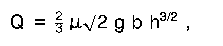
- the overflow quantity is preferably determined using the Poleni formula. This is where u is the overflow coefficient of the overflow threshold, g is the acceleration due to gravity, b is the width of the overflow threshold and h is the water level above the highest point of the standard profile crown.
- FIG. 1 shows a section 1 of a raw weir wall 2, on which an overflow threshold 3 is placed.
- the overflow threshold 3 is thus manufactured as a separate component and is -z. B. with the interposition of seals 4- by means of fasteners 5 held at the head of the pipe weir wall 2.
- the invention is not limited to such an embodiment, rather it also includes weirs in which the weir crown is not provided with an overflow threshold which can be fitted there, but rather the overflow threshold forms an integral part with the rest of the weir wall.
- the special profile shape of the overflow threshold is decisive.
- the overflow threshold 3 is composed of a standard profile crown 6 and a wide weir crown 7.
- the standard profile crown 6 has a shape that corresponds to the simulation of the underside of the jet of a ventilated, sharp-edged raid. According to the nomenclature of the practical hydraulic system, the shape of the wide weir crown can be described as a wide-crown weir.
- the drain back 8 of the standard profile crown 6 merges continuously into the horizontal surface plane 9 of the wide weir crown 7. This transition 10 is designed as a continuous, concave curvature 11.
- the standard profile crown 6 has a vertical dam wall 12 on the upper water side.
- the broad weir crown 7 has a sharp edge 13 on the underwater side. This is followed by a vertical weir rear wall 14.
- the width a of the standard profile crown 6 is approximately as large as the width b of the wide weir crown 7.
- the Surface level 9 of the wide weir crown 7 lies below the highest point 15 of the standard profile crown 6.
- the overflow threshold 3 is assigned a measuring device for height-dependent overflow measurement.
- the flow rate of the weir of Figure 1 is measured according to the Poleni formula.
- the Poleni formula is: where Q is the overflow quantity, u the overflow coefficient of the overflow threshold 3, g the acceleration due to gravity, b the width of the overflow threshold and h the water level above the highest point 15 of the standard profile crown 6.
- the Poleni formula thus represents a Q / h relationship with which an overflow measurement is easily possible.
- the prerequisite is that the raid coefficient u is known. Due to the overflow threshold profile according to the invention, this can be determined particularly easily and well by laboratory measurements. Unlike known profile shapes, it is essentially independent of influencing variables that would lead to measurement errors.
- the size l 1 corresponds to the wall thickness of the weir, which is limited to 40 centimeters in a preferred embodiment, there are design restrictions. These depend on the design head height h E between the highest point 15 of the standard profile crown 6 and the water level on the upper water side and the width 1 of the wide weir crown 7. If the distance c between the surface plane 9 and the highest point 15 increases, the width must consequently be increased 1 get smaller.
- Preferred weir heights of relief structures are in the range between 0.8 and 1.5 meters. This results in limit ratios for the quotient h E / w in the design hold-up area between 10 and 15 centimeters. respectively
- attack coefficients u and values of the Q / h characteristic curve are shown according to the Poleni formula of the overflow threshold 3 according to the invention. Intermediate values can be determined by interpollation.
- Overflow thresholds 3 lower than 0.8 meters result in an improvement in the relief capacity with approximately the same error.
- Overflow thresholds 3 higher than 1.5 meters mean no change in the characteristic or the table values.
Landscapes
- Engineering & Computer Science (AREA)
- Water Supply & Treatment (AREA)
- Health & Medical Sciences (AREA)
- General Engineering & Computer Science (AREA)
- Life Sciences & Earth Sciences (AREA)
- Hydrology & Water Resources (AREA)
- Public Health (AREA)
- Fluid Mechanics (AREA)
- General Physics & Mathematics (AREA)
- Mechanical Engineering (AREA)
- Physics & Mathematics (AREA)
- Structural Engineering (AREA)
- Civil Engineering (AREA)
- Business, Economics & Management (AREA)
- Emergency Management (AREA)
- Measuring Volume Flow (AREA)
- Treatment Of Fiber Materials (AREA)
- Measurement Of Levels Of Liquids Or Fluent Solid Materials (AREA)
Abstract
Description
- Die Erfindung betrifft eine Überlaufschwelle zur von der Höhe eines Flüssigkeitsspiegels abhängigen Überlaufmessung.
- Zunehmend werden in Mischwasser-Entwässerrungssystemen Regenüberlaufbecken gebaut und betrieben. Ziel dieser Maßnahme ist es, durch die, Regenwasserbehandlung den Regenabfluß zum Beispiel zu Kläranlagen so zu begrenzen, daß deren Wirkungsgrad nicht unzulässig sinkt und daß gleichzeitig eine stoßweise erfolgende Belastung von Vorflutern, zum Beispiel Flüssen und Gewässern, in vertretbaren Grenzen bleibt. Bis heute ist jedoch vielerorts der Wirkungsgrad und das Entlastungsverhalten derartiger Bauwerke nicht hinreichend bekannt. Die Auflagen der Aufsichtsbehörden einzelner Länder fordern daher (schon bei der Baugenehmigung) Becken und Regenüberläufe mit Meßeinrichtungen zu versehen, um eine Erfassung der Jahres- Entlastungsmenge zu ermöglichen. Mittelfristig ist überdies zu erwarten, daß auch an Regenüberlaufbecken und eventuell auch an exponierten Regenüberläufen eine Meßdatenerfassung zu Nachweiszwecken generell einzurichten ist.
- Für die Erfassung von Entlastungsmengen ist es bekannt, Überlaufschwellen einzusetzen, bei denen oberwasserseitig eine Wasserstandsmessung erfolgt. Insbesondere wird die Höhe des Wasserstandes oberhalb der Krone der Überlaufschwelle gemessen und aus dieser Meßgröße die Überlaufmenge ermittelt. Diese höhenabhängige Überlaufmessung ist besonders wirtschaftlich, jedoch bei den bekannten Einrichtungen mit vielfältigen Meßfehlern behaftet. Alternativ können für die Entlastungsmessung auch induktive Durchflußmesser eingesetzt werden. Diese induktiven Durchflußmesser sind Meßgeräte mit den zweifellos geringsten Meßfehlern. In die Entlastungsleitung, die in aller Regel als Freispiegelleitung ausgeführt ist, muß dann jedoch dieses Meßgerät in Verbindung mit einem gedükerten Meßrohr eingesetzt werden, weil ein ordnungsgemäßer Betrieb nur bei Meßrohrvollfüllung erreicht wird. Derartige Meßbauwerke erfordern jedoch extrem hohe Investitionskosten, so daß aus wirtschaftlichen Erwägungen in der Regel davon Abstand genommen werden muß. Diese Lösung bleibt nur außergewöhnlichen Betriebspunkten vorbehalten.
- Insofern befaßt sich die Erfindung mit der höhenabhängigen Überlaufmessung.
- Aufgabe der Erfindung ist es daher, eine Überlaufschwelle beziehungsweise eine Meßeinrichtung mit Überlaufschwelle anzugeben, die mit einfachen und kostengünstigen Mitteln eine weitestgehend fehlerfreie Überlaufmessung ermöglicht.
- Diese Aufgabe wird erfindungsgemäß dadurch gelöst, daß sich das Kronenprofil der Überlaufschwelle aus der Kombination einer Standardprofilkrone und einer sich an deren Abflußrücken anschließenden, waagerecht verlaufenden Breit-Wehrkrone zusammensetzt, wobei die Oberflächenebene der Breit-Wehrkrone unterhalb des höchsten Punktes der Standardprofilkrone liegt. Diese erfindungsgemäße, besondere Profilform der Überlaufschwelle stellt eine optimierte Schwellenform da, die gleichermaßen für die Aufgabe der Entlastung als auch einer Meßwerterfassung bestens geeignet ist. Sie ist eine Kombination zweier Überfallformen, die gemäß der praktischen Hydraulik als "Standardprofil" und als "breitkroniges Wehr" zu bezeichnen ist. Bei der erfindungsgemäßen Überlaufschwelle stellen sich transparente hydraulische Verhältnisse ein. Es liegt eine eindeutige, hydraulische Kennlinie vor, wobei sich stets ein stabiler Abflußstrahl innerhalb weiter Grenzen einstellt. Dies erfolgt unabhängig von der Belüftungssituation des Abflußstrahls. Bei dem erfindungsgemäßen Überlaufschwellenprofil ist es problemlos möglich, daß das Unterwasser über die Höhe der Wehrkrone ansteigt, ohne daß dabei der unvollkommene Überfall beginnt. Dies unterscheidet sich somit wesentlich von bekannten Überlaufschwellenprofilen, da zum Beispiel bei scharfkantigen Wehren die Beeinflussung des Oberwassers durch das Unterwasser bereits auftritt, bevor das Unterwasser die Wehrkrone erreicht hat. Mithin läßt die erfindungsgemäße Überlaufschwelle hohe Rückstauebenen zu. Ist sie mit einem Speicherbauwerk, zum Beispiel Regenüberlaufbecken, kombiniert, so läßt sich dessen Beckenvolumen in einem vergrößerten Bereich ausnutzen. Dies deshalb, weil der Überfallbeiwert (auf den im nachfolgenden noch näher eingegangen wird) bei dem erfindungsgemäßen Überlaufschwellenprofil mehr an dem Wert "1" liegt, so daß gegenüber bekannten Schwellen mit einer kleineren Überfallhöhe bei gleicher Abflußmenge gearbeitet werden kann. Diese Überfallhöhe ist jedoch in der Regel durch die baulichen Gegebenheiten begrenzt, um der Gefahr einer Wasseransammlung zum Beispiel in den Kellern von oberhalb liegenden Häusern zu begegnen. Da sich erfindungsgemäß eine kleinere Überfallhöhe ergibt, ergibt sich bei Ausnutzung des zulässigen Bereichs gegenüber den bekannten Einrichtungen ein Reservevolumen, das heißt, bei gleicher Beckenausbildung kann die erfindungsgemäße Überlaufschwelle höher angeordnet werden, so daß insgesamt ein größeres Beckenvolumen zur Verfügung steht. Andererseits ist es jedoch auch möglich, ein Becken mit geringerer Tiefe zu bauen, wobei sich dennoch -gegenüber bekannten Überlaufschwellen- gleiche Verhältnisse einstellen. Diese kleinere Beckentiefe bei gleichem Volumen senkt jedoch erheblich die Baukosten. Insbesondere ist es auch möglich, die erfindungsgemäße Überlaufschwelle in industrieller Fertigung herzustellen. Sie kann beispielsweise aus Kunststoff, insbesondere glasfaserverstärktem Kunststoff (GFK) hergestellt und auf die zumeist aus Beton hergestellte Rohschwelle aufgesetzt und dort befestigt werden.
- Vorstehend wurde bereits ausgeführt, daß sich stets ein stabiler Abflußstrahl innerhalb weiter Grenzen der Überfallhöhe einstellt. Während sich bei bekannten Überlaufschwellen in bestimmten Betriebspunkten Wirbel beziehungsweise Schwingungen einstellen, bleibt der Abflußstrahl bei der erfindungsgemäßen Überlaufschwelle stabil. Dies auch deshalb, weil keine Anhebung des Unterwasserstrahls in Abhängigkeit weiter Grenzen (ausgehend von der Entwurfsüberfallhöhe) erfolgt, wie dies oftmals bei bekannten Schwellen der Fall ist. Bei der erfindungsgemäßen Überlaufschwelle ist auch eine besonders einfache Auslegung im Zusammenhang mit einer Tauchwand möglich, da der störende Einfluß der Tauchwand auf die höhenabhängige Entlastungsmessung nach hydraulischen Gesetzen bestimmbar ist. Insofern kann dies berücksichtigt werden und führt dann nicht zu einer Meßwertverfälschung.
- Nach einer Weiterbildung der Erfindung ist der Übergang von dem Abflußrücken zur Oberflächenebene der Breit-Wehrkrone stetig, insbesondere als konkave Krümmung, ausgebildet. Hierdurch ist eine wirbelfreie Stromfädenausbildung bei geringer Reibung und gewünschter Druck- und Geschwindigkeitsverteilung gewährleistet.
- Vorzugsweise weist das Standardprofil oberwasserseitig eine senkrechte Stauwand auf. Unterseitig ist die Breit-Wehrkrone mit einer scharfen Kante versehen. Diese scharfe Kante grenzt vorzugsweise an eine senkrechte Wehrrückwand an.
- Die Form der Standardprofilkrone ist vorzugsweise derart ausgebildet, daß sie der Nachbildung der Strahlunterseite eines belüfteten scharfkantigen Überfalls entspricht.
- Günstig ist es, wenn die Breite der Standardprofilkrone etwa eben so groß ist, wie die Breite der Breit- Wehrkrone.
- Die Erfindung betrifft ferner eine Meßeinrichtung, der eine erfindungsgemäße Überlaufschwelle zugeordnet ist. Die Meßeinrichtung weist oberwasserseitig einen Wasserstandsmesser zur Bestimmung der Überlaufmenge auf. Der Wasserstandsmesser erfaßt vorzugsweise die oberwasserseitige Höhe des Wasserstandes oberhalb des höchsten Punktes der Standardprofilkrone. Dies erfolgt in einem Bereich, der noch nicht von der Überlaufschwelle beeinflußt ist. Als Wasserstandsmesser können bekannte Geräte mit Drucksensor, Echolot oder Einperlmessungseinrichtungen verwendet werden. Derartige Meßgeräte bestehen einerseits aus dem Sensor, der den Wasserstand ermittelt und weisen andererseits einen Meßverstärker mit normiertem Signalausgang auf. Nachgeschaltet wird vorzugsweise in der Regel ein Rechner, der das Höhensignal in ein schwellenbezogenes Mengensignal umwandelt. Ein Analogfrequenzwandler bildet mengenproportionale Impulse zur Ansteuerung eines m3-Zählers. Ferner ist es möglich Registrierschreiber oder -drucker zu installieren, so daß das Entlastungsergebnis protokolliert werden kann. Ferner können Fernübertragungseinrichtungen zur Übermittlung der Meßergebnisse vorhanden sein. Vorzugsweise wird die Überlaufmenge nach der Poleni-Formel ermittelt. Diese lautet

- Die Zeichnung veranschaulicht die Erfindung und zwar zeigt:
- Figur 1 einen Schnitt durch die erfindungsgemäße Überlaufschwelle und
- Figur 2 eine schematische Ansicht der Überlaufschwelle mit Darstellung verschieden hoher Wasserspiegel unter beziehungsweise über der Entwurfsüberfallhöhe.
- Die Figur 1 zeigt einen Abschnitt 1 einer Roh-Wehrmauer 2, auf die eine Überlaufschwelle 3 aufgesetzt ist. Die Überlaufschwelle 3 ist somit als separates Bauteil gefertigt und wird -z. B. unter Zwischenschaltung von Dichtungen 4- mittels Befestigungsmittel 5 am Kopf der Rohr-Wehrmauer 2 gehalten. Die Erfindung ist jedoch nicht auf eine derartige Ausgestaltung beschränkt, vielmehr beinhaltet sie auch Wehre, bei denen die Wehrkrone nicht mit einer aufsetzbaren, dort befestigten Überlaufschwelle versehen ist, sondern die Überlaufschwelle mit der übrigen Wehrmauer ein einstückiges Teil bildet. Entscheidend ist die besondere Profilform der Überlaufschwelle.
- Die Überlaufschwelle 3 setzt sich aus einer Standardprofilkrone 6 und einer Breit-Wehrkrone 7 zusammen. Die Standardprofilkrone 6 weist eine Form auf, die der Nachbildung der Strahlunterseite eines belüfteten, scharfkantigen Überfalls entspricht. Die Form der Breit-Wehrkrone ist -entsprechend der Nomenklatur der praktischen Hydraulik- als breitkroniges Wehr zu bezeichnen. Der Abflußrücken 8 der Standardprofilkrone 6 geht stetig in die waagerecht verlaufende Oberflächenebene 9 der Breit-Wehrkrone 7 über. Dieser Übergang 10 ist als stetige, konkave Krümmung 11 ausgebildet. Oberwasserseitig weist die Standardprofilkrone 6 eine senkrechte Stauwand 12 auf. Die Breit-Wehrkrone 7 besitzt unterwasserseitig eine scharfe Kante 13. An diese schließt sich eine senkrechte Wehrrückwand 14 an.
- Die Breite a der Standardprofilkrone 6 ist etwa ebensogroß, wie der Breite b der Breit-Wehrkrone 7. Die Oberflächenebene 9 der Breit-Wehrkrone 7 liegt unterhalb des höchsten Punktes 15 der Standardprofilkrone 6.
- Der Überlaufschwelle 3 ist eine Meßeinrichtung zur höhenabhängigen Überlaufmessung zugeordnet. Die Abflußmenge des Wehrs der Figur 1 wird nach der Poleni-Formel gemessen. Die Poleni-Formel lautet:
- Hierzu einige Erläuterungen:
- Das Standardprofil der Standardprofilkrone 6 ist -wie erwähnt- die Nachbildung der Strahlunterseite eines belüfteten, scharfkantigen Überfalls. Da für jede Überfallmenge Q eine andere Strahlunterseitenform existiert, wird die erfindungsgemäße Überlaufschwelle auf einen bestimmten Entwurfsfall hin ausgelegt. Hierzu gehören die Entwurfsüberfallmenge QE und die Entwurfsüberfallhöhe hE (vergleiche Figur 2). Bei der genannten Nachbildung erhält man eine Überfallform, die im Entwurfsfall ein druckfreies Profil ergibt, das heißt, entlang des gesamten Wehrrückens herrscht Atmosphärendruck. Für h < hE drostatische Druck ist. Für h >hE entsteht ein Unterdruck. Diese Druckverhältnisse bewirken eine Abflußbeschleunigung und somit eine Verbesserung der Abflußleistung. Das Standardprofil ist somit in der Lage eine wesentlich größere Abschlagmenge als andere Wehrformen bei gleicher Überfallhöhe h abzuführen. Die Größe des Unterdrucks nimmt bei steigender Überfallhöhe h zu. Dies kann bei bekannten Überlaufschwellenprofilen, insbesondere bei großen Überfallhöhen h, zur Strahlablösung beziehungsweise zu Kavitationserscheinungen führen. Durch die erfindungsgemäße Kombination eines Standardprofils mit einem breitkronigen Auslauf werden derartige Erscheinungen vermieden. Durch die Ausbildung des horizontal verlaufenden Schwellenteils (Breit-Wehrkrone 7) wird ferner erreicht, daß der Beginn des unvollkommenen Überfalls erst wesentlich später einsetzt. Gleichzeitig wird unter diesen Bedingungen der Überfallbeiwert u etwa ab dem 1,5-fachen der Entwurfsüberfallhöhe hE abnehmen. Die Abhängigkeit des Überfallbeiwerts u ergibt sich unter Berücksichtigung aller entscheidenden Einflußgrößen und den hydraulischen Modelgesetzen gemäß nachstehender Beziehung:

- Die Strömungsrichtung ist in der Figur 1 mit dem Pfeil 16 dargestellt.
- Da die Größe l1, der Wandstärke des Wehrs entspricht, wobei diese in einem bevorzugten Ausführungsbeispiel auf 40 Zentimeter begrenzt ist, ergeben sich konstruktive Einschränkungen. Diese sind abhängig von der Entwurfsüberfallhöhe hE zwischen dem höchsten Punkt 15 der Standardprofilkrone 6 und dem oberwasserseitigen Wasserspiegel sowie der Breite 1 der Breit-Wehrkrone 7. Wenn der Abstand c zwischen der Oberflächenebene 9 und dem höchsten Punkt 15 größer wird, muß folglich die Breite 1 kleiner werden.
- Bevorzugte Wehrhöhen von Entlastungsbauwerken liegen im Bereich zwischen 0,8 und 1,5 Meter. Dadurch ergeben sich im Entwurfsüberfallhöhenbereich zwischen 10 und 15 Zentimeter Grenzverhältnisse für den Quotienten hE/w.


- In der nachfolgenden Tabelle sind Überfallbeiwerte u und Werte der Q/h-Kennlinie entsprechend der Poleni-Formel der erfindungsgemäßen Überlaufschwelle 3 dargestellt. Zwischenwerte können durch Interpollation ermittelt werden.

- Einwandfreie Meßergebnisse lassen sich im Meßbereich zwischen annähernd 0 und dem 2,5-fachen des Entwurfsfalles erzielen. Bei einem angenommenen Entwurfsfall von hE = 10 Zentimetern und einer Schwellenhöhe von 1 Meter liegt ein gesicherter Meßbereich zwischen 0 und 25 Zentimeter Überfallhöhe entsprechend einer Entlastungsmenge zwischen 0 und 240 Liter pro Sekunde und laufendem Meter Schwellenlängserstreckung vor. Der dabei auftretende Fehler liegt zwischen 2,5 und 5%, abhängig von der Überfallhöhe h.
- Durch Veränderung des Entwurfüberfalls lassen sich bei etwa gleichem Fehler größere Wassermengen gemäß der folgenden Tabelle abschlagen.

- Niedrigere Überlaufschwellen 3 als 0,8 Meter bewirken eine Verbesserung des Entlastungsvermögens bei etwa gleichem Fehler. Höhere Überlaufschwellen 3 als 1,5 Meter bedeuten keine Veränderung der Kennlinie beziehungsweise der Tabellenwerte.
- Bei besonders langen Schwellen empfiehlt sich eine größere Meßstellenzahl, also der Einsatz mehrerer Wasserstandsmesser, in Verbindung mit einer Mittelwertbildung. Dabei sollte auch am Anfang und am Ende des Wehrs gemessen werden.
Claims (8)

Applications Claiming Priority (4)
| Application Number | Priority Date | Filing Date | Title |
|---|---|---|---|
| DE4030249 | 1990-09-25 | ||
| DE4030249 | 1990-09-25 | ||
| DE4108360A DE4108360C2 (de) | 1990-09-25 | 1991-03-15 | Überlaufschwelle |
| DE4108360 | 1991-03-15 |
Publications (2)
| Publication Number | Publication Date |
|---|---|
| EP0477745A1 true EP0477745A1 (de) | 1992-04-01 |
| EP0477745B1 EP0477745B1 (de) | 1994-09-14 |
Family
ID=25897153
Family Applications (1)
| Application Number | Title | Priority Date | Filing Date |
|---|---|---|---|
| EP91115806A Expired - Lifetime EP0477745B1 (de) | 1990-09-25 | 1991-09-18 | Messeinrichtung mit überlaufmessschwelle |
Country Status (3)
| Country | Link |
|---|---|
| EP (1) | EP0477745B1 (de) |
| AT (1) | ATE111544T1 (de) |
| ES (1) | ES2060264T3 (de) |
Cited By (2)
| Publication number | Priority date | Publication date | Assignee | Title |
|---|---|---|---|---|
| US6823729B2 (en) | 2002-05-06 | 2004-11-30 | Brombach Hansjoerg | Measuring weir for measuring flow volume at an overflow |
| BG65706B1 (bg) * | 2004-07-26 | 2009-07-31 | Иван КАЛЧЕВ | Устройство за измерване на водно количество в открити канали |
Citations (3)
| Publication number | Priority date | Publication date | Assignee | Title |
|---|---|---|---|---|
| US1499956A (en) * | 1923-07-17 | 1924-07-01 | Terzaghi Karl | Protection of buildings or weirs against hollowing out or washing away |
| US2103600A (en) * | 1935-12-21 | 1937-12-28 | John C Stevens | Scour prevention |
| FR822860A (fr) * | 1936-09-15 | 1938-01-10 | Neyret Beylier & Piccard Picte | Ouvrage évacuateur de crue |
-
1991
- 1991-09-18 EP EP91115806A patent/EP0477745B1/de not_active Expired - Lifetime
- 1991-09-18 ES ES91115806T patent/ES2060264T3/es not_active Expired - Lifetime
- 1991-09-18 AT AT91115806T patent/ATE111544T1/de not_active IP Right Cessation
Patent Citations (3)
| Publication number | Priority date | Publication date | Assignee | Title |
|---|---|---|---|---|
| US1499956A (en) * | 1923-07-17 | 1924-07-01 | Terzaghi Karl | Protection of buildings or weirs against hollowing out or washing away |
| US2103600A (en) * | 1935-12-21 | 1937-12-28 | John C Stevens | Scour prevention |
| FR822860A (fr) * | 1936-09-15 | 1938-01-10 | Neyret Beylier & Piccard Picte | Ouvrage évacuateur de crue |
Non-Patent Citations (1)
| Title |
|---|
| INSTRUMENT PRACTICE Bd. 17, Oktober 1963, Seiten 1065 - 1070; J.T. MILLER: 'FLOW MEASUREMENTS IN OPEN CHANNELS' * |
Cited By (2)
| Publication number | Priority date | Publication date | Assignee | Title |
|---|---|---|---|---|
| US6823729B2 (en) | 2002-05-06 | 2004-11-30 | Brombach Hansjoerg | Measuring weir for measuring flow volume at an overflow |
| BG65706B1 (bg) * | 2004-07-26 | 2009-07-31 | Иван КАЛЧЕВ | Устройство за измерване на водно количество в открити канали |
Also Published As
| Publication number | Publication date |
|---|---|
| EP0477745B1 (de) | 1994-09-14 |
| ES2060264T3 (es) | 1994-11-16 |
| ATE111544T1 (de) | 1994-09-15 |
Similar Documents
| Publication | Publication Date | Title |
|---|---|---|
| DE2653713C2 (de) | Unterdruck-Entwässerungsanlage für Gebäude | |
| EP0477745B1 (de) | Messeinrichtung mit überlaufmessschwelle | |
| DE4104451C2 (de) | Regenüberlaufbauwerk mit einer Meßeinrichtung zur Bestimmung der Überlaufwassermenge | |
| DE4108360C2 (de) | Überlaufschwelle | |
| DE3110104C2 (de) | Drosselvorrichtung | |
| DE3202354C2 (de) | Vorrichtung für den Flüssigkeitsabzug aus Becken o.dgl. | |
| DE10221319B4 (de) | Messwehr zur Ermittlung einer Abflussmenge an Regenentlastungen | |
| DE3418813A1 (de) | Entwaesserungssystem | |
| DE2406857C3 (de) | Vorrichtung für den Flüssigkeitsabzug aus Becken o.dgl., insbesondere Abwasserbecken | |
| DE2624059A1 (de) | Verfahren und einrichtung zur bestimmung des porenwasserdrucks in erde | |
| DE19601646C1 (de) | Meßanordnung zur Abflußmessung | |
| DE102016104656B4 (de) | Verfahren zur Messung von Überlaufmengen in Überlaufsystemen | |
| DE69109536T2 (de) | Schwimmventil mit Niveauregelung durch Gestell, insbesondere für Wasserbehälter von Sanitäranlagen. | |
| DE102020133121B4 (de) | Verfahren und Vorrichtung zur Überlaufmessung einer Flüssigkeit über eine Überlaufkante eines Beckens | |
| DE102004029567B4 (de) | Schmutzfangzelle | |
| DE19859742C1 (de) | Meßverfahren für den Durchfluß an einer Überfallschwelle | |
| DE4233371C9 (de) | Verfahren zum Messen des Durchflusses von Abwasser | |
| DE2731602C2 (de) | Vorrichtung zur kontinuierlichen Abflußmessung an einem Gerinne, das eine Überfallschwelle mit zeitlich und örtlich veränderlicher Fließtiefe aufweist | |
| DE4427425C2 (de) | Vorrichtung zur Begrenzung und Messung eines Volumenstromes | |
| DE4428421A1 (de) | Meßeinrichtung für Wassermengen | |
| DE435723C (de) | Verfahren und Vorrichtungen zur Verhuetung der UEberlastung von Klaeranlagen durch Niederschlagswasser und durch Geschiebe | |
| DE102008022320B4 (de) | Regenentlastungsbauwerk | |
| DE69932955T2 (de) | Vertikale Steuerungsvorrichtung einer biegsamen eintauchbaren Platte nebst entsprechendem Verfahren | |
| DE2735528C3 (de) | Vakuum-Entwässerungsanlage | |
| DE29703101U1 (de) | Einfache ohne Umbaumaßnahmen zu installierende Durchflußmeßeinrichtung für teilgefüllte Rohre und Kanäle auf Basis eines Meßverfahrens für vollgefüllte Leitungen |
Legal Events
| Date | Code | Title | Description |
|---|---|---|---|
| PUAI | Public reference made under article 153(3) epc to a published international application that has entered the european phase |
Free format text: ORIGINAL CODE: 0009012 |
|
| AK | Designated contracting states |
Kind code of ref document: A1 Designated state(s): AT BE CH DE DK ES FR GB IT LI NL SE |
|
| 17P | Request for examination filed |
Effective date: 19920330 |
|
| 17Q | First examination report despatched |
Effective date: 19920727 |
|
| GRAA | (expected) grant |
Free format text: ORIGINAL CODE: 0009210 |
|
| AK | Designated contracting states |
Kind code of ref document: B1 Designated state(s): AT BE CH DE DK ES FR GB IT LI NL SE |
|
| ITF | It: translation for a ep patent filed | ||
| PG25 | Lapsed in a contracting state [announced via postgrant information from national office to epo] |
Ref country code: GB Effective date: 19940914 Ref country code: DK Effective date: 19940914 Ref country code: BE Effective date: 19940914 |
|
| REF | Corresponds to: |
Ref document number: 111544 Country of ref document: AT Date of ref document: 19940915 Kind code of ref document: T |
|
| PG25 | Lapsed in a contracting state [announced via postgrant information from national office to epo] |
Ref country code: AT Effective date: 19940918 |
|
| REF | Corresponds to: |
Ref document number: 59102921 Country of ref document: DE Date of ref document: 19941020 |
|
| REG | Reference to a national code |
Ref country code: ES Ref legal event code: FG2A Ref document number: 2060264 Country of ref document: ES Kind code of ref document: T3 |
|
| PG25 | Lapsed in a contracting state [announced via postgrant information from national office to epo] |
Ref country code: SE Effective date: 19941214 |
|
| ET | Fr: translation filed | ||
| GBV | Gb: ep patent (uk) treated as always having been void in accordance with gb section 77(7)/1977 [no translation filed] |
Effective date: 19940914 |
|
| PLBE | No opposition filed within time limit |
Free format text: ORIGINAL CODE: 0009261 |
|
| STAA | Information on the status of an ep patent application or granted ep patent |
Free format text: STATUS: NO OPPOSITION FILED WITHIN TIME LIMIT |
|
| 26N | No opposition filed | ||
| PGFP | Annual fee paid to national office [announced via postgrant information from national office to epo] |
Ref country code: NL Payment date: 19960930 Year of fee payment: 6 |
|
| PG25 | Lapsed in a contracting state [announced via postgrant information from national office to epo] |
Ref country code: NL Free format text: LAPSE BECAUSE OF NON-PAYMENT OF DUE FEES Effective date: 19980401 |
|
| NLV4 | Nl: lapsed or anulled due to non-payment of the annual fee |
Effective date: 19980401 |
|
| PGFP | Annual fee paid to national office [announced via postgrant information from national office to epo] |
Ref country code: FR Payment date: 20000911 Year of fee payment: 10 |
|
| PGFP | Annual fee paid to national office [announced via postgrant information from national office to epo] |
Ref country code: CH Payment date: 20000921 Year of fee payment: 10 |
|
| PGFP | Annual fee paid to national office [announced via postgrant information from national office to epo] |
Ref country code: ES Payment date: 20001009 Year of fee payment: 10 |
|
| PG25 | Lapsed in a contracting state [announced via postgrant information from national office to epo] |
Ref country code: ES Free format text: LAPSE BECAUSE OF NON-PAYMENT OF DUE FEES Effective date: 20010919 |
|
| PG25 | Lapsed in a contracting state [announced via postgrant information from national office to epo] |
Ref country code: LI Free format text: LAPSE BECAUSE OF NON-PAYMENT OF DUE FEES Effective date: 20010930 Ref country code: CH Free format text: LAPSE BECAUSE OF NON-PAYMENT OF DUE FEES Effective date: 20010930 |
|
| PGFP | Annual fee paid to national office [announced via postgrant information from national office to epo] |
Ref country code: DE Payment date: 20011009 Year of fee payment: 11 |
|
| REG | Reference to a national code |
Ref country code: CH Ref legal event code: PL |
|
| PG25 | Lapsed in a contracting state [announced via postgrant information from national office to epo] |
Ref country code: FR Free format text: LAPSE BECAUSE OF NON-PAYMENT OF DUE FEES Effective date: 20020531 |
|
| REG | Reference to a national code |
Ref country code: FR Ref legal event code: ST |
|
| PG25 | Lapsed in a contracting state [announced via postgrant information from national office to epo] |
Ref country code: DE Free format text: LAPSE BECAUSE OF NON-PAYMENT OF DUE FEES Effective date: 20030401 |
|
| REG | Reference to a national code |
Ref country code: ES Ref legal event code: FD2A Effective date: 20021011 |
|
| PG25 | Lapsed in a contracting state [announced via postgrant information from national office to epo] |
Ref country code: IT Free format text: LAPSE BECAUSE OF NON-PAYMENT OF DUE FEES;WARNING: LAPSES OF ITALIAN PATENTS WITH EFFECTIVE DATE BEFORE 2007 MAY HAVE OCCURRED AT ANY TIME BEFORE 2007. THE CORRECT EFFECTIVE DATE MAY BE DIFFERENT FROM THE ONE RECORDED. Effective date: 20050918 |