EP0477761A2 - Dispositif d'affûtage de lames rotatives annulaires - Google Patents
Dispositif d'affûtage de lames rotatives annulaires Download PDFInfo
- Publication number
- EP0477761A2 EP0477761A2 EP91115871A EP91115871A EP0477761A2 EP 0477761 A2 EP0477761 A2 EP 0477761A2 EP 91115871 A EP91115871 A EP 91115871A EP 91115871 A EP91115871 A EP 91115871A EP 0477761 A2 EP0477761 A2 EP 0477761A2
- Authority
- EP
- European Patent Office
- Prior art keywords
- steeling
- blade
- members
- rods
- fixture
- Prior art date
- Legal status (The legal status is an assumption and is not a legal conclusion. Google has not performed a legal analysis and makes no representation as to the accuracy of the status listed.)
- Granted
Links
Images



Classifications
-
- B—PERFORMING OPERATIONS; TRANSPORTING
- B24—GRINDING; POLISHING
- B24B—MACHINES, DEVICES, OR PROCESSES FOR GRINDING OR POLISHING; DRESSING OR CONDITIONING OF ABRADING SURFACES; FEEDING OF GRINDING, POLISHING, OR LAPPING AGENTS
- B24B3/00—Sharpening cutting edges, e.g. of tools; Accessories therefor, e.g. for holding the tools
- B24B3/36—Sharpening cutting edges, e.g. of tools; Accessories therefor, e.g. for holding the tools of cutting blades
- B24B3/46—Sharpening cutting edges, e.g. of tools; Accessories therefor, e.g. for holding the tools of cutting blades of disc blades
-
- B—PERFORMING OPERATIONS; TRANSPORTING
- B24—GRINDING; POLISHING
- B24D—TOOLS FOR GRINDING, BUFFING OR SHARPENING
- B24D15/00—Hand tools or other devices for non-rotary grinding, polishing, or stropping
- B24D15/06—Hand tools or other devices for non-rotary grinding, polishing, or stropping specially designed for sharpening cutting edges
- B24D15/08—Hand tools or other devices for non-rotary grinding, polishing, or stropping specially designed for sharpening cutting edges of knives; of razors
-
- B—PERFORMING OPERATIONS; TRANSPORTING
- B26—HAND CUTTING TOOLS; CUTTING; SEVERING
- B26B—HAND-HELD CUTTING TOOLS NOT OTHERWISE PROVIDED FOR
- B26B25/00—Hand cutting tools involving disc blades, e.g. motor-driven
- B26B25/002—Motor-driven knives with a rotating annular blade
Definitions
- This invention relates to devices for steeling the cutting edge of annular rotary knife blades.
- Power driven rotary knives of a type used in the meat industry utilize annular blades supported in an annular housing secured to a handle that includes a drive mechanism for the blade. At intervals during use, it is desirable to realign the cutting edge of the blade with a so-called "steel.” This is analogous to the familiar use of a steel rod by chefs before carving with a straight knife.
- the present invention relates to devices that overcome the above and other disadvantages and assure accurate, controlled and improved steeling of the inside and outside annular surfaces that form a cutting edge of an annular rotary knife blade.
- the present invention provides apparatus for steeling an inside and an outside annular surface that together form a cutting edge of an annular rotary knife blade. It utilizes two steeling members, one for contacting the inside surface of the blade and the other for contacting the outside surface, and a knife fixture for receiving and orienting a knife blade relative to the steeling members.
- the knife fixture is movable relative to the steeling members along guiding means.
- the present invention also provides a device for concurrently steeling an inside and an outside annular surface that together form a cutting edge of an annular rotary knife blade. It utilizes a first steeling rod having a surface portion for steeling the outside surface and a second steeling rod for steeling the inside surface. The second rod is supported for movement relative to the first, and is biased to a position in contact with the inside surface of a blade that is in contact with the first rod.
- the present invention provides a device for concurrently steeling an inside and an outside annular surface that together form a cutting edge of an annular rotary knife blade and utilizes two steeling rods supported in a common plane for steeling the outside annular surface.
- a third steeling rod is supported for movement relative to the other rods, intersects the common plane, and has a surface portion for steeling the inside annular surface.
- the third rod is biased to a position in contact with the inside annular surface of the blade.
- the present invention utilizes a handle by which the operator can hold the device, although other means of support for the device can be used.
- first and second steeling rods of hard wear-resistant material are supported in a common plane, as by a handle, each having a surface portion for steeling the outside annular surface of the blade.
- a support extends from the handle on one side of the common plane and adjacent to the first and second rods.
- a third rod of hard wear-resistant material is carried by the support for reciprocating movement relative to the other rods, intersects said common plane and has a surface portion for steeling the inside annular surface of the blade.
- a spring or other means yieldably biases the third rod to a first position from which it is movable by the blade against the biasing force to establish yielding contact with the blade over a range of blade positions relative to the handle, and a knife fixture is carried by the handle and movable relative to the handle parallel to the common plane, whereby a rotating annular blade can be engaged with the three rods concurrently for steeling the cutting edge.
- two blade-steeling members are carried by the support and spaced from each other a distance sufficient to receive between them a portion of an annular rotary knife blade so that one can contact an inside annular blade surface and the other an outside annular blade surface.
- a knife fixture is carried by the handle and is movable along a defined path to guide an annular rotary knife blade into contact with the blade-steeling members.
- a spring or other means yieldably biases the fixture to a position relative to the steeling members in which the blade of a knife in the fixture is between the two steeling members, to facilitate entry and removal of the blade.
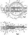
- a steeling device 10 ( Figures 1-5) is comprised of a handle 12, a rod mount 14 secured to the handle, first and second steeling rods 16, 18 for steeling the outside surface O (see Figure 6) of a rotary annular knife blade B of a rotary knife K, a third steeling rod 20 for steeling the inside surface I of the knife blade, a support rod 22 for a carriage 24 that carries the third steeling rod, and a fixture 26 reciprocable on the first and second steeling rods for properly locating the annular blade relative to the three steeling rods and for guiding it into engagement with the third steeling rod.
- the handle 12 has an eye hook 28 at one end 12a and an integral protective shield 30 and central axial bore 32 at the other end 12b.
- the rod mount 14 has a stud portion 36 that extends into the bore and an external block portion 38 that is located adjacent the end 12b of the handle.
- the rod mount is held in place by a retaining screw 40 received in a cross bore 42.
- a front face 44 of the block portion has two smooth-walled cylindrical bores 46, 47 in a common plane for receiving the first and second steeling rods 16, 18, and a third cylindrical bore 48 for receiving the support rod 22, all in cantilever fashion.
- Three retaining screws 50, 51, 52 in the block portion engage the rods 16, 18 and 22.
- the rods 16, 18 are spaced laterally in a common plane and are parallel to each other and equidistant from a vertical plane (in the orientation shown in the drawings) that contains the longitudinal axis A of the handle 12. It is preferred that the rods be of high carbon steel, serrated longitudinally, heat treated, and chrome plated.
- a peripheral annular groove 54, 55 and 56 is provided, respectively, in each rods 16, 18 and 22 adjacent the ends of the rods that extend into the cylindrical bores 46, 47 and 48. Each groove receives an end of the respective retaining screw 50 or 52.
- the screws 51, 52 and grooves 54, 55 permit rotational adjustment of the rods 16, 18 within the bores to present an unworn steeling surface to a position where it will be contacted by a blade being steeled.
- the support rod 22 is shorter than the steeling rods 16, 18, is oriented parallel to and below (in the orientation of the drawings) the steeling rods, coaxial with the central longitudinal axis A of the handle.
- the carriage 24 that slides on the rod 22 is of rectangular block-like construction, except for an inclined face 58 facing upward and toward the handle through which a bore 60 extends at right angles to the inclined face.
- the third steeling rod 20 is preferably of silicon carbide, is not serrated, and is tightly received in the bore 60. It extends a relatively short distance from and perpendicular to the face 58, and is located in a vertical plane that contains the central axis A.
- the carriage has a throughbore 61 that slidably receives the support rod 22.
- the carriage including the part defining the inclined face 58, extends upward from the support rod, between the steeling rods 16, 18.
- the width of the carriage is substantially equal to the spacing between the two steeling rods 16, 18, with a slight clearance.
- the steeling rods 16, 18 thereby restrain the carriage against rotation about the support rod.
- Two helical compression springs 62, 64 are carried on the support rod 22, one in front of and one behind the carriage 24.
- the spring 62 is retained by a stop ring 65 and the spring 64 and the carriage are retained on the rod 22 by the head of a screw 66 received in the distal end of the rod.
- the fixture 26 has two upstanding sidewalls 68, 70 spaced longitudinally of the steeling rods 16, 18 and joined by two L-shaped longitudinally extending front and back walls 72, 74 (see Figure 3) of lesser height and integral with lower portions of the side walls.
- the sidewall 68 has an aperture 75 located and sized to slidably receive the support rod 22. It also has two spaced apertures 76, 77 and the sidewall 70 has two spaced apertures 78, 79, all of which are located and sized to slidingly receive the steeling rods 16, 18, which are sufficiently longer than the fixture to accommodate relative sliding of the fixture along the rods 16, 18, the length of travel being approximately one-half inch in the embodiment shown.
- the sidewall 68 is adjacent the handle 12 and has an outwardly facing surface 68a that is flat and adapted to abut the flat front face 44 of the rod mount 14, and an inwardly facing surface 68b that has two flat portions P1 in which the aperture 76 for the rod 16 is formed and P2 in which the aperture 77 for the rod 18 is formed.
- the portion P1 is parallel to the outwardly facing surface 68a while the portion P2 is inclined away from the surface 68a and forms an obtuse included angle with the portion P1 in top plan, the apex of which is adjacent the vertical plane passing through the axis A.
- the sidewall 70 has a flat and straight inwardly facing surface 70a that extends perpendicular to the vertical plane passing through the axis A and parallel to the face 44, and an arcuate surface 70b at an upper portion of the sidewall and adjacent the rod 16, for receiving an end APE of an arcuate portion AP of the knife handle KH and serving as a positive locating surface for properly positioning the knife in the fixture.
- the sidewall 70 also has an inturned flange 70c at the top edge.
- the stop ring 65 is fixed to the support rod 22 between the carriage 24 and the sidewall 68 of the fixture.
- the compression spring 62 is between the stop ring 65 and the sidewall 68, while the compression spring 64 is between the carriage and the head of the screw 66.
- the lengths of the springs are such that, in the absence of a force applied to the fixture, the two springs will be under slight compression, thereby biasing the wall 68 against the face 44 of the rod mount and biasing the carriage against the stop ring.
- the location of the stop ring maintains the carriage spaced from the wall 68.
- the spring 62 and stop ring 65 allow limited travel of the fixture, while the spring 64 and screw 66 allow limited travel of the carriage.
- the permitted carriage travel is slightly greater than the permitted fixture travel, thereby assuring that the carriage is always under a yieldable bias toward the wall 68 and against a blade B that is brought into contact with the third steeling rod 20 when the fixture is moved through its full travel away from the handle.
- a knife K of the type shown and described in more detail in U. S. Patent No. 4,492,027 is inserted into the fixture 26.
- the knife is the type in which the blade B has a frusto-conical shape and is carried in a circular housing H secured to an arcuate portion AP of the knife handle KH.
- the cutting edge E of the blade B is below the housing in the orientation shown in the drawings.
- the housing and blade are inserted into the fixture from above the front wall 72 and back wall 74, are moved toward the back wall until stopped by the side walls, and are brought into a plane parallel to the plane of the steeling rods 16, 18.
- the knife and fixture After insertion of the knife into the fixture, and with the operator applying light pressure to the blade against the rods 16, 18, the knife and fixture are moved parallel to the steeling rods 16, 18 away from the surface 44 (to the right in the orientation of Figures 1, 2, 4 and 5), to bring the inside surface I of the blade into contact with the steeling rod 20.
- the movement will be continued until the spring 62 is fully compressed and the spring 64 is partially compressed to maintain the rod 20 in yieldably biased contact with, and under sufficient pressure against, the surface I to steel the inside surface of the blade directly adjacent the cutting edge.
- the surface I is frusto-conical and inclined at substantially the angle at which the steeling rod 20 extends from the carriage.
- the rod 20 will extend at a slight angle (1/2 to 1°)relative to the inside surface to assure that it contacts the inside surface at the cutting edge.
- a proper relationship between the steeling rod 20 and the blade B is assured because the rod is in the vertical plane passing through the axis A and the center C of the annular blade.
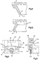
- a second embodiment of the invention for use with a knife K' having an annular power-driven blade B' of somewhat different construction from the knife K and blade B is shown in Figures 7-11.
- a power-driven rotary knife having a blade of the type that this embodiment of a steeling device is adapted to steel is shown in more detail in U. S. Patent Nos. 4,509,261 and 4,637,140.
- a steeling device 110 is comprised of a handle 112, a rod mount 114 secured to the handle, a first support rod 115 for supporting a first steeling rod 116 for steeling the outside surface O' of a rotary annular knife blade B' of a rotary knife K' and a second steeling rod 118 for steeling the inside surface I' of the knife blade, a second support rod 120, and a fixture 126 reciprocable on the first and second support rods for receiving and positioning the knife K' with its blade B' in proper position for steeling, and for guiding the blade into contact with the steeling rods so the outside surface O' directly adjacent the cutting edge E' of the rotary knife blade B' can be selectively brought into proper contact with the steeling rod 116 and the inside surface I' directly adjacent the cutting edge E' can be selectively brought into contact with the steeling rod 118 while the blade is driven in rotation.
- the handle 112 has an eye 128 at one end 112a and an integral protective shield 130 and central axial bore 132 at the other end 112b.
- the rod mount 114 has a stud portion 136 that extends into the bore and an external block portion 138 that is located adjacent the end 112b of the handle.
- the rod mount is held in place by a retaining screw 140 received in a cross bore 142.
- a front face 144 of the block portion has a smooth-walled cylindrical bore 146 and a threaded cylindrical bore 148 in a common plane (vertical in the orientation of the drawings) for receiving the first and second support rods 115, 120, both in cantilever fashion.
- a retaining screw 150 in the block portion engages the rod 115 and holds it against rotation.
- the rods 115 and 120 are spaced vertically in a common plane, are substantially equal in length, and are parallel to each other.
- the bore 152 receives the steeling rod 116 and the bore 154 receives the steeling rod 118.
- the steeling rods are relatively short and as a result of the orientation of the bores, converge outwardly from the rod 115 in a common vertical plane, with their distal ends spaced from each other a distance sufficient to accommodate the fixture 126 and entry and removal of the blade B' and housing H' (a distance of approximately three-fourths of an inch in the embodiment shown).
- the steeling rod 116 is positioned to contact the outside surface O' adjacent the cutting edge E' and the steeling rod 118 is positioned to contact the inside surface I' adjacent the cutting edge. Accordingly, the angles at which they extend from the support rod are controlled by the angle of the blade surface against which they will bear.
- the rods that contact the blade are cylindrical, as in the embodiment shown, it is desirable that the rods extend at substantially the same angle as the blade's surfaces, preferable differing by about 1/2 to 1° to assure that the steeling rods contact the inside and outside surfaces directly at the cutting edge.
- a longitudinal threaded bore 156 is provided in the end of the rod 115 that is received in the rod mount 114 and a longitudinal threaded bore 158 is provided in the opposite or distal end of the rod 115.
- the bore 156 intersects the transverse bore 152 and the bore 158 intersects the transverse bore 154.
- Set screws 160, 162 are received, respectively, in the longitudinal bores 156, 158 to secure the steeling rods in a desired position, and an end screw 164 closes the bore 158.
- the two steeling rods 116, 118 are constructed of high carbon steel, heat treated and hard chrome plated. They are identical in construction and only the rod 116 will be described in detail.
- the rod 116 has two longitudinal portions, 116a that is cylindrical and extends from the support rod 115 and is preferably longitudinally serrated and located to engage a blade, and 116b that is received within the bore 152 and is also cylindrical but of smaller diameter than the portion 116a.
- the portion 116b has a peripheral groove 166 located to be aligned with and to receive a nylon cross pin 168 in the support rod 115.
- the pin and groove retain the steeling rod 116 in the bore 152 while permitting rotation of the steeling rod within the bore when the set screw 160 is withdrawn from contact with the steeling rod portion 116b. Rotation of the steeling rod allows an operator to move a worn surface of the rod from a location where it contacts the blade being steeled and present an unworn surface.
- the fixture 126 has a body portion 170 from which two side walls 172, 174 depend in the orientation of the drawings, and from which an upstanding guide 175 extends.
- the body portion has a longitudinal groove 176 that opens downward and closely conforms in cross sectional size and shape to the support rod 115, which is slidingly received therein.
- the downward opening 178 is wide enough to accommodate the depending steeling rod 118 past which the fixture moves along the support rod.
- the depending sidewalls 172, 174 are both offset to one side of the groove, as illustrated in Figure 9, to avoid interfering with and to fully expose a blade B' to the steeling rods.
- the sidewalls converge in the direction of their offset and preferably have cylindrically curved inwardly facing surfaces 172a, 174a, respectively, the curvature and spacing of the walls being compatible with the outside diameter of the circular knife housing H'. This assures that when the housing and blade are fully inserted into the fixture, as illustrated in Figure 7, the housing will abut the walls and the blade B' will have a diameter coinciding with a vertical plane that contains the central longitudinal axis A' of the support rod 115. Knives are available with housings and blades of various diameters.
- the fixture must be of a size designed for the blade diameter, and fixtures of different sizes can be accommodated on the support rod 115 or on a longer rod, if necessary.
- the fixture can be reversed so the wall 174 is closest to the handle to accommodate operators who hold the knife in their left hand.
- the upstanding guide 175 is directly over the groove 176 and midway between the sidewalls 172, 174 in the embodiment shown.
- a cylindrical passage 180 in the guide extends parallel to the groove 176 and receives the second support rod 120.
- a first portion 182 at one end of the rod 120 is threaded and is received in the rod mount 114 so that the rod extends parallel to and in a common vertical plane with the support rod 115.
- a second portion 184 of the rod 120 at the opposite end is of smaller diameter, to form a shoulder 185. The portion 184 receives the guide 175, preventing relative rotation of the fixture about the support rod 115.
- a first helical compression spring 186 surrounds the portion 184 between the shoulder 185 and the guide 175, and a second helical compression spring 188 surrounds the portion 184 between the guide and the head of a screw 190 received in the distal end of the rod 120.
- the two springs 186, 188 locate the fixture so that the depending sidewall 172 is between and substantially equally spaced from the two steeling rods 116, 118.
- the length of the rod portion 184 and the construction of the springs are sufficient to allow movement of the fixture along the two support rods, in opposite directions from the neutral position shown in Figures 5 and 6, to an extent that will bring a knife blade B' selectively into contact first with one steeling rod and then with the other as an operator moves the knife and slides the fixture first in one direction along the two support rods and then in the other, while the blade is rotated.
- the operator places the housing H' and blade B' in the fixture from below and then moves the knife and fixture laterally to bring the blade first into contact with one of the steeling rods and then with the other, applying the blade against the steels with light pressure and retaining it in contact for a short time as the blade rotates.
- the operator may choose which steeling rod is used last, the one that contacts the inside surface I' of the blade or the one that contacts the outside surface O', since this will have a slight effect on the cutting action of the blade by virtue of positioning the so-called burr of the cutting edge to the inside or the outside of the blade.
Landscapes
- Engineering & Computer Science (AREA)
- Mechanical Engineering (AREA)
- Life Sciences & Earth Sciences (AREA)
- Forests & Forestry (AREA)
- Accessories And Tools For Shearing Machines (AREA)
- Finish Polishing, Edge Sharpening, And Grinding By Specific Grinding Devices (AREA)
- Coating Apparatus (AREA)
Applications Claiming Priority (2)
| Application Number | Priority Date | Filing Date | Title |
|---|---|---|---|
| US590167 | 1990-09-28 | ||
| US07/590,167 US5099721A (en) | 1990-09-28 | 1990-09-28 | Steeling apparatus for annular rotary knife blades |
Publications (3)
| Publication Number | Publication Date |
|---|---|
| EP0477761A2 true EP0477761A2 (fr) | 1992-04-01 |
| EP0477761A3 EP0477761A3 (en) | 1992-05-06 |
| EP0477761B1 EP0477761B1 (fr) | 1995-07-05 |
Family
ID=24361144
Family Applications (1)
| Application Number | Title | Priority Date | Filing Date |
|---|---|---|---|
| EP91115871A Expired - Lifetime EP0477761B1 (fr) | 1990-09-28 | 1991-09-18 | Dispositif d'affûtage de lames rotatives annulaires |
Country Status (4)
| Country | Link |
|---|---|
| US (1) | US5099721A (fr) |
| EP (1) | EP0477761B1 (fr) |
| DE (1) | DE69111008T2 (fr) |
| ES (1) | ES2075287T3 (fr) |
Cited By (1)
| Publication number | Priority date | Publication date | Assignee | Title |
|---|---|---|---|---|
| EP0816026A1 (fr) * | 1996-06-28 | 1998-01-07 | Bettcher Industries, Inc. | Lame de couteau rotative |
Families Citing this family (24)
| Publication number | Priority date | Publication date | Assignee | Title |
|---|---|---|---|---|
| US5931065A (en) * | 1997-05-19 | 1999-08-03 | Jackson; Roger Lee | Hand tool with axially repositionable shaft |
| US6769184B1 (en) | 1998-07-22 | 2004-08-03 | Bettcher Industries, Inc. | Low friction rotary knife |
| US6634257B2 (en) * | 2002-01-15 | 2003-10-21 | John W. Long | Sharpening method and apparatus for rotary knives |
| US8448340B2 (en) * | 2010-02-01 | 2013-05-28 | Bettcher Industries, Inc. | Large diameter notched blade and blade housing for power operated rotary knife |
| US8756819B2 (en) | 2010-04-12 | 2014-06-24 | Bettcher Industries, Inc. | Power operated rotary knife with disposable blade support assembly |
| US8540553B2 (en) | 2010-10-28 | 2013-09-24 | Jim Bagley | Portable power sharpener for hand held rotary cutter blades |
| US8695222B2 (en) | 2011-07-25 | 2014-04-15 | Bettcher Industries, Inc. | Power operated rotary knife |
| US8745881B2 (en) | 2011-07-25 | 2014-06-10 | Bettcher Industries, Inc. | Power operated rotary knife |
| US8806761B2 (en) | 2011-07-25 | 2014-08-19 | Bettcher Industries, Inc. | Power operated rotary knife |
| US8950076B2 (en) | 2011-07-25 | 2015-02-10 | Bettcher Industries, Inc. | Power operated rotary knife |
| US8739416B2 (en) | 2011-07-25 | 2014-06-03 | Bettcher Industries, Inc. | Power operated rotary knife |
| US8726524B2 (en) | 2011-07-25 | 2014-05-20 | Bettcher Industries, Inc. | Power operated rotary knife |
| US10537356B2 (en) | 2014-06-16 | 2020-01-21 | Exsurco Medical, Inc. | Power operated rotary excision tool |
| USD907205S1 (en) | 2012-09-07 | 2021-01-05 | Exsurco Medical, Inc. | Power operated rotary excision tool |
| US10022146B2 (en) | 2015-05-29 | 2018-07-17 | Exsurco Medical, Inc. | Power operated rotary excision tool |
| US9833919B2 (en) | 2015-10-02 | 2017-12-05 | Bettcher Industries, Inc. | Power operated rotary knife |
| US10124500B2 (en) | 2016-12-09 | 2018-11-13 | Bettcher Industries, Inc. | Cam-actuated split blade housing for power operated rotary knife |
| US10471614B2 (en) | 2016-12-09 | 2019-11-12 | Bettcher Industries, Inc. | Cam-actuated split blade housing for power operated rotary knife |
| USD1094052S1 (en) | 2016-12-09 | 2025-09-23 | Bettcher Industries, Inc. | Annular blade |
| US10040211B2 (en) | 2016-12-09 | 2018-08-07 | Bettcher Industries, Inc. | Power operated rotary knife |
| USD973115S1 (en) | 2018-01-26 | 2022-12-20 | Bettcher Industries, Inc. | Annular blade |
| USD912489S1 (en) | 2019-06-13 | 2021-03-09 | Bettcher Industries, Inc. | Housing for a power operated rotary knife |
| US11077571B2 (en) | 2019-10-02 | 2021-08-03 | Bettcher Industries, Inc. | Split blade housing with expansion sleeve assembly for power operated rotary knife |
| US20230311265A1 (en) * | 2022-04-05 | 2023-10-05 | Robert T. Williams | Kitchen article and methods |
Family Cites Families (4)
| Publication number | Priority date | Publication date | Assignee | Title |
|---|---|---|---|---|
| US3406486A (en) * | 1965-12-13 | 1968-10-22 | Bettcher Industries | Sharpening device for rotary knives |
| US3349485A (en) * | 1966-01-10 | 1967-10-31 | Bettcher Industries | Rotary knife with sharpener |
| US4142291A (en) * | 1977-10-17 | 1979-03-06 | Bettcher Industries, Inc. | Trimming knife |
| US4854046A (en) * | 1987-10-07 | 1989-08-08 | Bettcher Industries, Inc. | Rotary hand trimming knife |
-
1990
- 1990-09-28 US US07/590,167 patent/US5099721A/en not_active Expired - Fee Related
-
1991
- 1991-09-18 DE DE69111008T patent/DE69111008T2/de not_active Expired - Fee Related
- 1991-09-18 ES ES91115871T patent/ES2075287T3/es not_active Expired - Lifetime
- 1991-09-18 EP EP91115871A patent/EP0477761B1/fr not_active Expired - Lifetime
Cited By (2)
| Publication number | Priority date | Publication date | Assignee | Title |
|---|---|---|---|---|
| EP0816026A1 (fr) * | 1996-06-28 | 1998-01-07 | Bettcher Industries, Inc. | Lame de couteau rotative |
| US5940972A (en) * | 1996-06-28 | 1999-08-24 | Bettcher Industries, Inc. | Rotary knife blade |
Also Published As
| Publication number | Publication date |
|---|---|
| DE69111008T2 (de) | 1996-03-14 |
| US5099721A (en) | 1992-03-31 |
| ES2075287T3 (es) | 1995-10-01 |
| DE69111008D1 (de) | 1995-08-10 |
| EP0477761B1 (fr) | 1995-07-05 |
| EP0477761A3 (en) | 1992-05-06 |
Similar Documents
| Publication | Publication Date | Title |
|---|---|---|
| EP0477761B1 (fr) | Dispositif d'affûtage de lames rotatives annulaires | |
| US5400546A (en) | Precision twist drill sharpener/point splitting machine | |
| US5667427A (en) | Method and apparatus for sharpening curved blades | |
| EP0286266A1 (fr) | Appareil pour affûter des outils de coupe | |
| US5810649A (en) | Tool guide for sharpening woodcarving and tools | |
| US6244938B1 (en) | Drill grinder | |
| US4977671A (en) | Saw for cutting large diameter shielded conduit | |
| US3879899A (en) | Scissors sharpener | |
| US4575969A (en) | Grinding machine for punching tools | |
| US4359819A (en) | Quick clamping device to hold BX cables | |
| US4532736A (en) | Sharpening device | |
| CA1093309A (fr) | Aiguisoir de scie mecanique | |
| US4677881A (en) | Chain saw sharpener | |
| US4974372A (en) | Universal device for sharpening drill bits | |
| US5035670A (en) | Cutter height adjustment means | |
| US3891015A (en) | Constant depth cutter assembly | |
| US20050142992A1 (en) | Angle positioning tool and hand-scaler grinding device using same | |
| CA1279485C (fr) | Affuteuse de forets | |
| EP2321090B1 (fr) | Dispositif d'affûtage d'une pointe de foret hélicoïdal et son procédé d'utilisation | |
| US3930342A (en) | Sharpener for twist drills | |
| EP0263513A2 (fr) | Affûteuse de forets ayant un support pour foret inclus des mandrins pour serrer la queue et le corps du foret | |
| US4742648A (en) | Drill sharpening tool | |
| USRE31504E (en) | Saw chain sharpening fixture | |
| US4198950A (en) | Dressing device for wheels or the like | |
| US4177697A (en) | Apparatus for sharpening a chain saw |
Legal Events
| Date | Code | Title | Description |
|---|---|---|---|
| PUAI | Public reference made under article 153(3) epc to a published international application that has entered the european phase |
Free format text: ORIGINAL CODE: 0009012 |
|
| PUAL | Search report despatched |
Free format text: ORIGINAL CODE: 0009013 |
|
| AK | Designated contracting states |
Kind code of ref document: A2 Designated state(s): DE ES FR GB IT |
|
| AK | Designated contracting states |
Kind code of ref document: A3 Designated state(s): DE ES FR GB IT |
|
| 17P | Request for examination filed |
Effective date: 19921102 |
|
| 17Q | First examination report despatched |
Effective date: 19931116 |
|
| RAP1 | Party data changed (applicant data changed or rights of an application transferred) |
Owner name: BETTCHER INDUSTRIES, INC. |
|
| GRAA | (expected) grant |
Free format text: ORIGINAL CODE: 0009210 |
|
| AK | Designated contracting states |
Kind code of ref document: B1 Designated state(s): DE ES FR GB IT |
|
| REF | Corresponds to: |
Ref document number: 69111008 Country of ref document: DE Date of ref document: 19950810 |
|
| ITF | It: translation for a ep patent filed | ||
| REG | Reference to a national code |
Ref country code: ES Ref legal event code: FG2A Ref document number: 2075287 Country of ref document: ES Kind code of ref document: T3 |
|
| ET | Fr: translation filed | ||
| PLBE | No opposition filed within time limit |
Free format text: ORIGINAL CODE: 0009261 |
|
| STAA | Information on the status of an ep patent application or granted ep patent |
Free format text: STATUS: NO OPPOSITION FILED WITHIN TIME LIMIT |
|
| 26N | No opposition filed | ||
| PGFP | Annual fee paid to national office [announced via postgrant information from national office to epo] |
Ref country code: FR Payment date: 19970818 Year of fee payment: 7 |
|
| PGFP | Annual fee paid to national office [announced via postgrant information from national office to epo] |
Ref country code: DE Payment date: 19970825 Year of fee payment: 7 |
|
| PGFP | Annual fee paid to national office [announced via postgrant information from national office to epo] |
Ref country code: GB Payment date: 19970826 Year of fee payment: 7 |
|
| PGFP | Annual fee paid to national office [announced via postgrant information from national office to epo] |
Ref country code: ES Payment date: 19970929 Year of fee payment: 7 |
|
| PG25 | Lapsed in a contracting state [announced via postgrant information from national office to epo] |
Ref country code: GB Free format text: LAPSE BECAUSE OF NON-PAYMENT OF DUE FEES Effective date: 19980918 |
|
| PG25 | Lapsed in a contracting state [announced via postgrant information from national office to epo] |
Ref country code: ES Free format text: LAPSE BECAUSE OF NON-PAYMENT OF DUE FEES Effective date: 19980919 |
|
| GBPC | Gb: european patent ceased through non-payment of renewal fee |
Effective date: 19980918 |
|
| PG25 | Lapsed in a contracting state [announced via postgrant information from national office to epo] |
Ref country code: FR Free format text: LAPSE BECAUSE OF NON-PAYMENT OF DUE FEES Effective date: 19990531 |
|
| PG25 | Lapsed in a contracting state [announced via postgrant information from national office to epo] |
Ref country code: DE Free format text: LAPSE BECAUSE OF NON-PAYMENT OF DUE FEES Effective date: 19990701 |
|
| REG | Reference to a national code |
Ref country code: FR Ref legal event code: ST |
|
| REG | Reference to a national code |
Ref country code: ES Ref legal event code: FD2A Effective date: 19991013 |
|
| PG25 | Lapsed in a contracting state [announced via postgrant information from national office to epo] |
Ref country code: IT Free format text: LAPSE BECAUSE OF NON-PAYMENT OF DUE FEES;WARNING: LAPSES OF ITALIAN PATENTS WITH EFFECTIVE DATE BEFORE 2007 MAY HAVE OCCURRED AT ANY TIME BEFORE 2007. THE CORRECT EFFECTIVE DATE MAY BE DIFFERENT FROM THE ONE RECORDED. Effective date: 20050918 |