EP0477975A2 - Doppelwandige Hochdruckentladungslampe - Google Patents
Doppelwandige Hochdruckentladungslampe Download PDFInfo
- Publication number
- EP0477975A2 EP0477975A2 EP91116567A EP91116567A EP0477975A2 EP 0477975 A2 EP0477975 A2 EP 0477975A2 EP 91116567 A EP91116567 A EP 91116567A EP 91116567 A EP91116567 A EP 91116567A EP 0477975 A2 EP0477975 A2 EP 0477975A2
- Authority
- EP
- European Patent Office
- Prior art keywords
- arc tube
- outer envelope
- straight portions
- discharge lamp
- high pressure
- Prior art date
- Legal status (The legal status is an assumption and is not a legal conclusion. Google has not performed a legal analysis and makes no representation as to the accuracy of the status listed.)
- Withdrawn
Links
Images


Classifications
-
- H—ELECTRICITY
- H01—ELECTRIC ELEMENTS
- H01J—ELECTRIC DISCHARGE TUBES OR DISCHARGE LAMPS
- H01J61/00—Gas-discharge or vapour-discharge lamps
- H01J61/02—Details
- H01J61/30—Vessels; Containers
- H01J61/34—Double-wall vessels or containers
Definitions
- the present invention relates to a jacketed high pressure discharge lamp having an outer envelope and an arc tube held in the outer envelope and, in particular, a lamp effective to be used for a ceramics discharge lamp whose arc tube is comprised of a U-shaped, transparent ceramic tube.
- a high-pressure sodium vapor discharge lamp is of such a jacketed that its outer envelope holds an arc tube therein serving as a discharge tube.
- the arc tube is made of a light-transparent ceramics, such as transparent alumina tube, and has a pair of electrodes one at each end thereof which are hermetically sealed therein together with sodium as a light emitting material, mercury as a metal for a buffer gas and a rare gas for starting.
- the light-transparent alumina tube is excellent in heat-resistance and in corrosion-resistance to the sodium and suitable to the use of a discharge bulb of this type of discharge lamp.
- the light-transparent alumina tube is high in melting point and hard to soften and manufacture.
- a straight type tube which is formed by an extrusion-molding method is employed as an arc tube as such.
- a jacketed lamp has been developed by molding a U-shaped tube as an arc tube with the use of alumina and fitting the arc tube of transparent alumina ceramics in an outer envelope.
- the discharge lamp in general, has a nature such that an arc generated between the electrodes passes across the shortest electrode-to-electrode distance.
- the arc tube if being U-shaped, has a tendency that the arc moves nearer the inner bent wall. The deflection of the arc overheats the inner bent wall of the U-shaped arc tube.
- a jacketed high pressure discharge lamp comprising an outer envelope having a closed end as one end and a pinch-sealed section at the other end; an arc tube contained in the outer envelope and defining a space relative to the outer envelope, the arc tube being comprised of a U-shaped transparent ceramic tube, having straight portions parallel to each other and a bent portion connected to each one end of the straight portions, being held in the outer envelope with the bent portion located on the closed end of the outer envelope and the other end of the straight portion directed toward the pinch-sealed section of the outer envelope, and having light emitting metal and rare gas filled therein; and a pair of electrodes sealingly provided in the arc tube, each, at the other end of the straight portion, wherein the outer envelope and arc tube are so spaced as to satisfy the following condition: S1 ⁇ S2 where
- Fig. 1 shows a high-pressure sodium vapor discharge lamp whose rated input power is 70 W.
- Reference numeral 1 shows an outer envelope made of quartz.
- the outer enbelope 1 is closed at one end 2 and sealed, as a pinch-sealed section, at the other end 3.
- a cylindrical section 4 circular in cross-section is formed between these ends 2 and 3.
- the outer envelope 1 is evacuated and maintained at a predetermined vacuum level.
- a base cap 5 made of, for example, ceramics, is fitted over the pinch-sealed section 3.
- the base cap 5 is cemented to the pinch-sealed section 3 by an insulation cement 6 and a pair of base pins 7, 7 are projected at the base cap 5.
- the arc tube 10 is enclosed in the outer envelope 1 with a space left therebetween.
- the arc tube 10 is comprised of a discharge tube of a generally U-shaped configuration made of a light-transmissive alumina.
- the U-shaped arc tube 10 comprises, as shown in Fig. 4, straight portions 11, 11 substantially parallel to each other and a bent portion 12 connecting these straight portions 11, 11 at one end of the straight section.
- the other end (open end) of each straight portion 11 is closed by a corresponding ceramics disk 13.
- a pair of electrodes 14, 14 are each mounted on the corresponding disks 13, 13 in a manner to be located in the straight portions 11, 11 and comprised of an electrode rod and a coil wound around the electrode rod.
- An emitter of at least one kind selected from the group consisting of yttrium oxide, thorium oxide and rare earth metal oxide is deposited on the electrode coil.
- Electrical lead through 15 and 15 comprised of a niobium tube extend through the ceramics disks 13 and 13 and are connected to the electrodes 14 and 14.
- the conductive tubes 15 and 15 provide the coolest area at their outer side.
- the electrical lead through 15 and 15 are connected to lead wires/support wires 16 and 16.
- the lead wires/support wires 16 and 16 are connected to metal foil conductors 8 and 8 made of, for example, molybdenum and sealed to the pinch-sealed section 3 of the outer envelope 1.
- the metal foil conductors 8 and 8 are connected to outer lead wires 9 and 9.
- the outer lead wires 9 and 9 are connected to the base pins 7 and 7.
- Both the ends of the arc tube are directed towards the pinch-sealed section 3 side of the outer envelope 1 and the bent portion 12 is directed toward the closed end 2 of the outer envelope 1. In this way, the arc tube is held within the outer envelope.
- the corresponding portion of the outer envelope is pinched in a direction perpendicular to that in which the straight portions 11 and 11 of the arc tube are aligned to each other.
- the outer envelope 1 and arc tube 10 are so spaced that, as shown in Fig. 3.
- S1 ⁇ S2 where S1 shows a distance between the outer surface of the straight portion of the arc tube and the inner surface of the outer envelope as viewed in a direction of a line passing through each axis of the straight portions of the arc tube, and S2 shows a distance between the outer surface of the straight portions of the arc tube and the inner surface of the outer envelope as viewed both in a direction perpendicular to a line passing through each axis of the straight portion of arc tube and in a direction passing through the axis of the arc tube.
- the distance S1 is set to be 1 to 3 mm.
- a distance n between a midpoint on an imaginary curvature of the inner surface of the outer envelope at the closed end 2 and the outer surface of the bent portion of the arc tube as shown in Fig. 2 is set to be 5 to 15 mm.
- the arc tube 10 has a relation as set out below: 3 mm ⁇ d ⁇ 5 mm (1) and 1.6 ⁇ l/d ⁇ 6 (2) where
- the U-shaped bent portion 12 connecting the straight portions 11 and 11 of the arc tube 10 provides a light emitting area and hence light substantially coming from the bent portion 12 of the arc tube is externally emitted through the outer envelope 1.
- the high pressure sodium lamp is started with a maximum current of 2 amperes and provides a light output of about 3500 lm at an input power of 70 W during a steady lighting time.
- the length of the outer envelope 1 becomes about half as small as that of the conventional counterpart. It is thus possible to largely reduce the size of the lamp and to attach it to a small-sized lighting fixture.
- the outside wall 11b of the straight portion of the arc tube 10 is located nearer the outer envelope 1.
- the distance S1 is set to be about 1.2 to 2.0 mm at a 70 W lamp.
- heat emitted from the straight portions 11 of the arc tube 10 is transmitted as radiant heat to the outer envelope 1 and a temperature rise occurs in the outer envelope 1 at those areas nearer the straight portions of the arc tube 10.
- the heat reflected on the outer envelope 1 is transmitted as radiant heat to the straight portions 11 of the arc tube 10. That is, as the straight portions 11 of the arc tube are located nearer the outer envelope 1, the outside wall 11b of the straight portions 11 receives the radiant heat from the outer envelope 1, causing a temperature rise there.
- the distance S2 as defined above is naturally greater than 1 to 3 mm.
- the curvature radius of the bent portion 12 of the arc tube can be regarded as corresponding to one half the distance l between the straight portions 11 and 11 of the arc tube 10. It is, therefore, better to increase the distance l between the straight portions 11 and 11 of the arc tube.
- a heated area inside the bent portion 12 is spaced apart from the outer bent wall of the bent portion 12, a temperature difference between the inner and outer bent walls of the bent portion 12 becomes greater, producing heat distortion. If, therefore, the inner diameter d of the bent portion 12 is decreased, it is possible to decrease a temperature difference across the width of the bent portion.
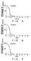
- the inventors of the present invention have examined the relation between the distance l and the inner diameter d set out above.
- Figs. 5 to 7 show the percentage of occurrence of cracks upon testing under the condition that the relation of the distance l and inner diameter d set out above varies at a high pressure sodium vapor discharge lamp of about 70 W.
- each lamp was turned ON and OFF 1000 times at a 30% overload state and the percentage of occurrence of cracks was measured.
- the inner diameter d of the arc tube is satisfactory for the high color rendering type high pressure sodium vapor discharge lamp belonging in the order of 50 to 150 W.
- the coolest area at the end of one straight section 11 or at the forward end of the electrical lead through 15 receives no radiant heat from the other straight portion 11 and electrode 14 of said other straight portion of the arc tube.
- the coolest temperature area is not raised in temperature and the vapor pressure of sodium in the arc tube is not raised to a predetermined level, thus causing a lowering in color characteristic.
- n is set to be 5 to 15 mm, a greater spacing is left between the outer envelope 1 and the arc tube 10, thus imparting the radiant heat from the outer envelope 1 to the bent portion 12 of the are tube. It is, therefore, possible to control a temperature rise at the bent portion 12 serving as a major light emitting area.
- the pinch-sealed section 3 of the outer envelope 1 is formed in the direction perpendicular to the plane in which the straight portions 11 and 11 are aligned to each other, a smaller spacing can be provided at a zone near the pinch-sealed section of the outer envelope 1. That is, if at the end portion of the outer envelope 1 a pinch-sealed section is formed in the same direction as that in which the straight portions 11 and 11 are aligned with each other, the pinching section has to be formed in a lower position due to the presence of the straight portions 11 and 11.
- the pinching section is formed in the direction perpendicular to that in which the straight portions 11 and 11 are aligned to each other, the pinching section can be formed in a relatively high position, reducing the spacing size on the pinch-sealed section 3 side.
- the coolest areas at the outer ends of the electrical lead throughs 15 and 15 is located nearer the wall of the outer envelope 1 and these areas receive heat from the wall of the outer envelope 1 and a temperature rise is liable to occur.
- the present invention can be applied not only to the high pressure sodium vapor discharge lamp but also to other lamps, such as an HID lamp.
- the outer envelope 1 has been explained as being maintained in a vacuum state, the outer envelope may be maintain in a vacuum state for an arc tube of 70 W or below, but the rare gas, such as argon, xenon and kripton, is desirably filled in the outer envelope 1 in which case a lamp has an input power exceeding 70 W.
- the rare gas such as argon, xenon and kripton
- the distance S1 has been explained as being smaller than the distance S2
- the outside wall 11b side of the straight portion is located nearer the outer envelope and receives radiant heat from the outer envelope, causing a temperature rise there.
- a temperature difference between the outside wall 11b and the inside wall 11a of the straight portion becomes smaller and hence the temperature gradient is alleviated along the periphery of the straight portions of the arc tube, causing less heat distortion. It is possible to prevent a damage to the arc tube.
Landscapes
- Vessels And Coating Films For Discharge Lamps (AREA)
Applications Claiming Priority (2)
| Application Number | Priority Date | Filing Date | Title |
|---|---|---|---|
| JP2259142A JPH04137452A (ja) | 1990-09-28 | 1990-09-28 | セラミック放電灯 |
| JP259142/90 | 1990-09-28 |
Publications (2)
| Publication Number | Publication Date |
|---|---|
| EP0477975A2 true EP0477975A2 (de) | 1992-04-01 |
| EP0477975A3 EP0477975A3 (en) | 1992-09-23 |
Family
ID=17329915
Family Applications (1)
| Application Number | Title | Priority Date | Filing Date |
|---|---|---|---|
| EP19910116567 Withdrawn EP0477975A3 (en) | 1990-09-28 | 1991-09-27 | Jacketed high pressure discharge lamp |
Country Status (3)
| Country | Link |
|---|---|
| EP (1) | EP0477975A3 (de) |
| JP (1) | JPH04137452A (de) |
| KR (1) | KR940004552B1 (de) |
-
1990
- 1990-09-28 JP JP2259142A patent/JPH04137452A/ja active Pending
-
1991
- 1991-09-27 KR KR91016866A patent/KR940004552B1/ko not_active Expired - Fee Related
- 1991-09-27 EP EP19910116567 patent/EP0477975A3/en not_active Withdrawn
Also Published As
| Publication number | Publication date |
|---|---|
| EP0477975A3 (en) | 1992-09-23 |
| KR920007063A (ko) | 1992-04-28 |
| KR940004552B1 (en) | 1994-05-25 |
| JPH04137452A (ja) | 1992-05-12 |
Similar Documents
| Publication | Publication Date | Title |
|---|---|---|
| EP0443964B1 (de) | Niederleistungsmetallhalogenidlampe | |
| EP0581423B1 (de) | Universelle Metallhalogenidlampe | |
| US4970431A (en) | High-pressure sodium discharge lamp with fins radially extending from the discharge vessel for controlling the wall temperature of the discharge vessel | |
| KR20000070635A (ko) | 금속-할로겐 화합물 램프 | |
| US20030062831A1 (en) | Ceramic HID lamp with special frame wire for stabilizing the arc | |
| US5532543A (en) | High density discharge lamp with pinched-on containment shield | |
| EP0720208B1 (de) | Kreisförmige Fluoreszenzlampe | |
| EP0186899B1 (de) | Metallhalogenidlampe mit Bogenröhrenschildstütze | |
| KR920010056B1 (ko) | 편밀봉형 금속증기 방전등 | |
| US4620125A (en) | Low wattage metal halide lamp with inverted domed sleeve | |
| EP0477975A2 (de) | Doppelwandige Hochdruckentladungslampe | |
| US4978887A (en) | Single ended metal vapor discharge lamp with insulating film | |
| JP4599359B2 (ja) | 高圧放電ランプ | |
| WO2003012823A1 (en) | Ceramic hid lamp with special frame for stabilizing the arc | |
| JPH0582093A (ja) | セラミツク放電灯 | |
| JPS63218147A (ja) | 放電ランプ | |
| EP0596676B1 (de) | Hochdrucknatriumentladungslampe | |
| JP3573297B2 (ja) | 低電力形メタルハライドランプ | |
| JP2586682B2 (ja) | 片封止形金属蒸気放電灯 | |
| EP0604207B1 (de) | Metall-Halogen Bogen Lampe | |
| JPH11204083A (ja) | セラミック製放電ランプ | |
| JPS60200455A (ja) | 小形メタルハライドランプ | |
| JP2003109539A (ja) | メタルハライドランプおよび照明装置 | |
| JP3159576B2 (ja) | メタルハライドランプ | |
| EP0492726A1 (de) | Hochdrucknatriumlampe mit Reflektor |
Legal Events
| Date | Code | Title | Description |
|---|---|---|---|
| PUAI | Public reference made under article 153(3) epc to a published international application that has entered the european phase |
Free format text: ORIGINAL CODE: 0009012 |
|
| 17P | Request for examination filed |
Effective date: 19911024 |
|
| AK | Designated contracting states |
Kind code of ref document: A2 Designated state(s): DE GB |
|
| PUAL | Search report despatched |
Free format text: ORIGINAL CODE: 0009013 |
|
| AK | Designated contracting states |
Kind code of ref document: A3 Designated state(s): DE GB |
|
| 17Q | First examination report despatched |
Effective date: 19940620 |
|
| STAA | Information on the status of an ep patent application or granted ep patent |
Free format text: STATUS: THE APPLICATION IS DEEMED TO BE WITHDRAWN |
|
| 18D | Application deemed to be withdrawn |
Effective date: 19941101 |