EP0478095B1 - Machine à travailler le sol pour la préparation du lit de semence - Google Patents
Machine à travailler le sol pour la préparation du lit de semence Download PDFInfo
- Publication number
- EP0478095B1 EP0478095B1 EP91203161A EP91203161A EP0478095B1 EP 0478095 B1 EP0478095 B1 EP 0478095B1 EP 91203161 A EP91203161 A EP 91203161A EP 91203161 A EP91203161 A EP 91203161A EP 0478095 B1 EP0478095 B1 EP 0478095B1
- Authority
- EP
- European Patent Office
- Prior art keywords
- distributing
- carrier
- seed
- machine
- soil cultivating
- Prior art date
- Legal status (The legal status is an assumption and is not a legal conclusion. Google has not performed a legal analysis and makes no representation as to the accuracy of the status listed.)
- Expired - Lifetime
Links
- 239000002689 soil Substances 0.000 title claims abstract description 31
- 230000007246 mechanism Effects 0.000 claims abstract description 31
- 238000010276 construction Methods 0.000 description 14
- 238000009331 sowing Methods 0.000 description 6
- 239000000969 carrier Substances 0.000 description 4
- 239000000463 material Substances 0.000 description 4
- 230000005540 biological transmission Effects 0.000 description 3
- 239000003381 stabilizer Substances 0.000 description 3
- 230000000694 effects Effects 0.000 description 2
- 238000005096 rolling process Methods 0.000 description 2
- 210000001364 upper extremity Anatomy 0.000 description 2
- 230000002411 adverse Effects 0.000 description 1
- 230000008878 coupling Effects 0.000 description 1
- 238000010168 coupling process Methods 0.000 description 1
- 238000005859 coupling reaction Methods 0.000 description 1
- 230000002349 favourable effect Effects 0.000 description 1
Images

Classifications
-
- A—HUMAN NECESSITIES
- A01—AGRICULTURE; FORESTRY; ANIMAL HUSBANDRY; HUNTING; TRAPPING; FISHING
- A01B—SOIL WORKING IN AGRICULTURE OR FORESTRY; PARTS, DETAILS, OR ACCESSORIES OF AGRICULTURAL MACHINES OR IMPLEMENTS, IN GENERAL
- A01B63/00—Lifting or adjusting devices or arrangements for agricultural machines or implements
- A01B63/14—Lifting or adjusting devices or arrangements for agricultural machines or implements for implements drawn by animals or tractors
- A01B63/24—Tools or tool-holders adjustable relatively to the frame
- A01B63/32—Tools or tool-holders adjustable relatively to the frame operated by hydraulic or pneumatic means without automatic control
-
- A—HUMAN NECESSITIES
- A01—AGRICULTURE; FORESTRY; ANIMAL HUSBANDRY; HUNTING; TRAPPING; FISHING
- A01B—SOIL WORKING IN AGRICULTURE OR FORESTRY; PARTS, DETAILS, OR ACCESSORIES OF AGRICULTURAL MACHINES OR IMPLEMENTS, IN GENERAL
- A01B49/00—Combined machines
- A01B49/02—Combined machines with two or more soil-working tools of different kind
- A01B49/022—Combined machines with two or more soil-working tools of different kind at least one tool being actively driven
- A01B49/025—Combined machines with two or more soil-working tools of different kind at least one tool being actively driven about a substantially vertical axis
-
- A—HUMAN NECESSITIES
- A01—AGRICULTURE; FORESTRY; ANIMAL HUSBANDRY; HUNTING; TRAPPING; FISHING
- A01B—SOIL WORKING IN AGRICULTURE OR FORESTRY; PARTS, DETAILS, OR ACCESSORIES OF AGRICULTURAL MACHINES OR IMPLEMENTS, IN GENERAL
- A01B49/00—Combined machines
- A01B49/04—Combinations of soil-working tools with non-soil-working tools, e.g. planting tools
- A01B49/06—Combinations of soil-working tools with non-soil-working tools, e.g. planting tools for sowing or fertilising
- A01B49/065—Combinations of soil-working tools with non-soil-working tools, e.g. planting tools for sowing or fertilising the soil-working tools being actively driven
-
- A—HUMAN NECESSITIES
- A01—AGRICULTURE; FORESTRY; ANIMAL HUSBANDRY; HUNTING; TRAPPING; FISHING
- A01B—SOIL WORKING IN AGRICULTURE OR FORESTRY; PARTS, DETAILS, OR ACCESSORIES OF AGRICULTURAL MACHINES OR IMPLEMENTS, IN GENERAL
- A01B63/00—Lifting or adjusting devices or arrangements for agricultural machines or implements
- A01B63/14—Lifting or adjusting devices or arrangements for agricultural machines or implements for implements drawn by animals or tractors
- A01B63/24—Tools or tool-holders adjustable relatively to the frame
-
- A—HUMAN NECESSITIES
- A01—AGRICULTURE; FORESTRY; ANIMAL HUSBANDRY; HUNTING; TRAPPING; FISHING
- A01B—SOIL WORKING IN AGRICULTURE OR FORESTRY; PARTS, DETAILS, OR ACCESSORIES OF AGRICULTURAL MACHINES OR IMPLEMENTS, IN GENERAL
- A01B73/00—Means or arrangements to facilitate transportation of agricultural machines or implements, e.g. folding frames to reduce overall width
- A01B73/02—Folding frames
- A01B73/04—Folding frames foldable about a horizontal axis
- A01B73/042—Folding frames foldable about a horizontal axis specially adapted for actively driven implements
-
- A—HUMAN NECESSITIES
- A01—AGRICULTURE; FORESTRY; ANIMAL HUSBANDRY; HUNTING; TRAPPING; FISHING
- A01C—PLANTING; SOWING; FERTILISING
- A01C7/00—Sowing
- A01C7/20—Parts of seeders for conducting and depositing seed
- A01C7/201—Mounting of the seeding tools
- A01C7/203—Mounting of the seeding tools comprising depth regulation means
-
- A—HUMAN NECESSITIES
- A01—AGRICULTURE; FORESTRY; ANIMAL HUSBANDRY; HUNTING; TRAPPING; FISHING
- A01C—PLANTING; SOWING; FERTILISING
- A01C15/00—Fertiliser distributors
- A01C15/005—Undercarriages, tanks, hoppers, stirrers specially adapted for seeders or fertiliser distributors
- A01C15/006—Hoppers
Definitions
- the present invention relates to a soil cultivating machine for the preparation of a seed bed, comprising a seed container and a central frame portion, to which two carrier beams are coupled, each carrying a set of seed pipes, which carrier beams are pivotable about horizontal axes extending in the direction of operative travel (A) between an operative and an inoperative position, and which carrier beams, in said operative position, are aligned horizontally and extend transversely to the direction of operative travel (A), said machine further being provided with two distributing mechanisms, each being connected to said container by means of a supply tube and each being capable of distributing seed through flexible tubes to one of the sets of seed pipes of a respective carrier beam.
- a suchlike machine is known from the DE-A 2519760.
- the machine described herein comprises distributing members connected to a hopper disposed closely in front of the carrier beams and centrally above the set of carrier beams. According to this document it would be possible to reduce the working width of the machine, assumably by deflecting an outer carrier beam around an axis extending in the operative direction.
- the upward deflection of a carrier beam would in this construction ultimately be limited by the fixed position of the distributing members. In practice such a deflection would also be limited due to adverse tangling of the flexible tubes connecting each distributing member with the respective seed pipes.
- each distributing mechanism is pivotally associated to one of said carrier beams by means of a pivot axis which extends parallel to the carrier beam, and in that adjusting means are provided for tilting said distribution mechanism about said pivot axis in a direction perpendicular to its associated carrier beam so as to enable said carrier beam being raised into its substantially vertical transport position without the distributing mechanisms contacting other machine parts.
- each carrier beam is coupled to a respective lateral frame portion, which lateral frame portion is pivotably connected to the central frame portion.
- each distributing mechanism is mounted on a respective lateral frame portion.
- the machine comprisesd in that the distributing mechanisms are, taken in a direction transversely to the direction of operative travel, each disposed at a different distance relative to a mirror plane between the two carrier beams.
- the machine may comprise a rotary harrow disposed in front of the seed pipes and connected to the frame parts laterally connected to the central frame part.
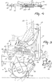
- the implement shown in the drawings concerns a soil cultivating machine, in particular one for the preparation of a seed bed.
- the machine comprises a frame beam 1 which extends transversely to the direction of operative travel A and is located at least substantially horizontally.
- the frame beam 1 consists of three portions which are in alignment and are pivotably interconnected by means of pins 2 extending in the direction of operative travel A.
- the central portion is provided with a trestle 3 having a three-point connection for coupling to the three-point lifting hitch of a tractor.
- hydraulical adjusting cylinders 4 Between the outer portions and the trestle 3 there are provided hydraulical adjusting cylinders 4, by means of which said outer portions can be folded relative to said central portion about the pins 2.
- each of the outer portions of the frame beam 1 are each provided with a ground wheel 5 which is adjustable in height by means of a threaded spindle. Furthermore, each of the outer portions of the frame beam 1 is provided near its end with a hinged parallelogram construction 7, by means of which a carrier 8 is arranged movably in height relative to the portions.
- Each parallelogram construction 7 comprises two arms, which are superposed and are pivotably mounted on an upwardly directed plate arranged at the upper side of a carrier 8.
- Each of the carriers 8, which are in alignment supports at least substantially vertical shafts of soil working members 12, which shafts are interspaced equidistantly at preferably 25 cms.
- each of the respective carriers 8 is closed by means of an upwardly directed plate 15 extending at least substantially parallel to a vertical plane in the direction of operative travel A of the machine.
- each of the plates 15 is provided with a pin extending transversely to the direction of operative travel A, the arrangement being such that the pins are in alignment.
- an arm 17, which arm extends rearwardly along the outer side of the plate 15.
- Each arm 17 has a front portion which extends at least substantially horizontally and merges into a portion 19 extending obliquely downwardly and rearwardly. Between the ends of the portions 19 there is arranged freely rotatably a roller 20 by means of shafts 21 supported in bearing housings.
- the roller 20 is designed as a packer roller with scraper members 24.
- Each of the scraper members 24 is provided at a lower end of an obliquely upwardly and rearwardly extending arm 25.
- the arms 25 are mounted together on a carrier or beam 26, which extends at least substantially parallel to the axis of rotation of the roller 20.
- the carrier 26 is arranged near the upper ends of hook-shaped arms 27 which, by means of their other, forwardly directed ends, are freely rotatable about the shafts 21 of the roller 20.
- a cross beam or carrier 30 By means of a pair of lugs and a pin extending in the direction of operative travel A, there is arranged between the arms 17 an end of a cross beam or carrier 30, which beam extends at least substantially parallel to the axis of rotation of the roller 20.
- the cross beam 30 together with the arms 17 constitutes a carrier construction for the roller 20.
- the other end of the stabilizer rod 33 is arranged movably about a vertical pin provided near the centre at the rear side of a carrier 8.
- the length of the stabilizer rod 33 is adjustable.
- the front portions of the arms 17 are each provided with a guide means, which are located at the inner sides and co-operate with the rear sides of the plates 15.
- a horizontal pin mounted to the carrier 30 and extending transversely to the direction of operative travel A, there is arranged freely movably a threaded spindle 36, which spindle is also connected to a carrier 8.
- the spindle 36 By means of the spindle 36 the working depth of a carrier 8 relative to a roller can be adjusted.
- the upper end of each hook-shaped arm 27 is provided with a rod 28 which is arranged movably by means of a pin.
- the other end of the rod 28 is mounted near the threaded spindle 36 on the cross beam 30 by means of a pin ( Figure 1).
- the length of the rod 28 is adjustable.
- each carrier 26 for the scraper members 24 of a roller 20 there are arranged at equal distance from the ends rearwardly extending brackets 44, on which is mounted a carrier beam 45 which extends transversely to the direction of operative travel A and over the entire width of the roller 20 ( Figure 1).
- the carrier beam 45 is located at least substantially parallel to the carrier 26.
- each of the seed pipes 46 is connected to a distributing mechanism 49 of a pneumatical seed drill 50.
- each of the distributing mechanisms 49 is mounted on each of the two rightmost brackets 44.
- a supply tube 51 which near the upper side of the trestle 3 is supported on the frame beam 1 and which furthermore, when the machine is coupled, is passed to the front over the top side of the tractor, each of the distributing mechanisms 49 is connected to a fan and a container 51A.
- the container 51A and the fan are mounted on a frame 52 arranged at the lifting hitch at the front side of the tractor.
- the frame 52 is supported by a roller 53 which extends transversely to the direction of operative travel A and may be designed as a packer roller.
- the fan may be driven from the power take-off shaft at the front side of the tractor, while a supply mechanism for the supply of seed material from the container is driven by means of a wheel 54 rolling over the ground.
- each of the carriers 8 there is mounted on the shafts of the respective soil working members 12 a pinion, the arrangement being such that the pinions on the shafts of adjacent soil working members are in driving connection with each other.
- the shaft of a soil working member 12 is extended and reaches by means of this extension to into a gear box 56.
- the extension is in driving connection via a bevel gear transmission with a shaft which extends transversely to the direction of operative travel A and is bearing-supported therein, which shaft is in driving connection via a speed variator 57 located at the outer side of the gear box with a shaft which also extends transversely to the direction of operative travel A and projects beyond the gear box at the other side.
- telescopic shafts 58 By means of telescopic shafts 58 provided with universal joints, the relevant shafts are connected to the ends of a shaft which also extends transversely to the direction of operative travel A and is bearing-supported in a gear box 59 mounted on a bracket located at the rear side of the central portion of the frame beam 1.
- gear box 59 Inside the gear box 59, the shaft extending transversely to the direction of operative travel A is in driving connection via a bevel gear transmission with a shaft which extends in the direction of operative travel A and projects beyond the gear box both at the front side and at the rear side.
- the end of the shaft projecting at the front side is connected to the power take-off shaft of the tractor by means of an intermediate shaft 61.
- the implement is coupled to the three-point lifting hitch of the tractor by means of the trestle 3 and from the power take-off shaft via the intermediate shaft 61 and the above-described transmission there is obtained such a drive for the soil working members 12 that adjacent soil working members are rotated in opposite directions and thereby cultivate by means of their soil working elements at least adjoining strips of soil.
- the respective frame portions of the frame beam assume a fixed position relative to each other by means of a locking means (not shown in further detail).
- the machine rests on the ground by means of the height-adjustable ground wheels 5.
- the spindle 36 and the rollers 20 located behind the soil working members 12, which rollers, as stated above, each are designed as a packer roller it is possible to set the working depth of the soil working members 12 prior to starting the job.
- This setting can be effected by means of the adjusting devices provided on the cross beam 30 and constituted by the threaded spindles 36, which adjusting devices are movably connected to the rear side of a carrier 8 by means of connecting strips constituting a guide for a carrier 8.
- the distributing mechanisms 49 and the seed pipes 46 of the seed drill 50 are mounted on a carrier 26 which is supported by means of the hook-shaped arms 27 which is freely movable about the shafts 21 of the packer rollers 20. In this connection, the free movability is limited by means of the rods 28.
- a carrier 8 Upon a change in the working depth of the soil working members 12, it is possible to effect an after-setting of the seed pipes 46 and the scraper members 24.
- this movement is also passed through the parallelogram constructions 7 at the front side. In this manner there is obtained a movement in upward direction, while there is hardly any change in the position of the soil working members nor in the working.
- the outer frame portions of the frame beam 1 can be folded about the pins 2 extending in the direction of operative travel A by means of the hydraulical adjusting cylinders 4.
- the respective distributing mechanisms 49 are positioned side by side, so that they do not constitute an impediment to a compactly folded position.
- the frame 52 provided at the front side of the tractor can be lifted by means of a separate lifting hitch, so that the whole can be transported.
- Figures 3 and 4 illustrate an embodiment wherein there is arranged an adjusting cylinder 62 instead of the rods 28 between the carrier or beam 26 for the scrapers and the arm 17 constituting part of the carrier construction for the roller 20.
- the piston rod of the adjusting cylinder 62 by means of a fork-like portion and a pin 63.
- the housing of said adjusting cylinder is arranged pivotably at an upwardly extending lug 66 on the upper side of the arm 17 by means of a pin 65.
- the upper side of said housing of the adjusting cylinder 62 includes a stop 66A located between two plate-shaped portions 67, which portions are attached to the end of the piston rod. In two places, the plate-shaped portions are provided with three rows of superjacent apertures 68.
- Into said apertures 68 may be inserted the legs of a brace 69, which legs can be secured by means of a split pin ( Figure 4).
- the legs of the brace 69 serve as stops for co-operation with the stops 66A, the arrangement being such that hereby the stroke of the adjusting cylinder 62 can be limited.
- the distributing mechanisms 49 are arranged pivotably relative to the bracket 44 by means of a transverse shaft 70 extending at least substantially in the horizontal direction.
- a transverse shaft 70 extending at least substantially in the horizontal direction.
- an adjusting rod 72 Between the upper side of a support 71 for the distributing mechanism 49 and the cross beam 30 there is provided an adjusting rod 72, the ends of which are arranged pivotably to the support 71 and the cross beam 30, respectively.
- the distributing mechanism 49 can be pivoted rearwardly about the shaft 70 located at the lower side by means of said adjusting rod 72, so that, when the outer frame portions of the frame beam 1 are folded upwardly, the distributing mechanisms do not contact other machine parts.
- the adjusting cylinders 62 forming adjusting members and being provided between the carrier or beam 26 and the arms 17
- the carrier 26 upon turning at the head of the field the carrier 26 can be pivoted about the shafts 21 of the roller 20, as a result of which said carrier with the brackets 44 and the seed pipes arrives into the position as indicated by dash lines ( Figure 3). In doing so, this pivotal movement is limited by the rear leg of the brace 69.
- the lifting of the implement during turning at the head of the field prevents the seed pipes from being distorted and/or clogged with soil.
- the front leg of the brace 69 ensures that, when the implement is brought into the working position again, the carrier 26 is returned to the same position as before, so that the same sowing depth can be maintained. It is also possible to change the sowing depth by means of the brace 69, i.e. by removing the front leg thereof further towards the rear an increase in sowing depth will be obtained.
Landscapes
- Life Sciences & Earth Sciences (AREA)
- Soil Sciences (AREA)
- Environmental Sciences (AREA)
- Engineering & Computer Science (AREA)
- Mechanical Engineering (AREA)
- Zoology (AREA)
- Soil Working Implements (AREA)
- Agricultural Machines (AREA)
- Pretreatment Of Seeds And Plants (AREA)
Claims (8)
- Machine pour travailler le sol pour la préparation d'un lit de semis, comprenant un récipient à semences (51A) et une partie de châssis centrale à laquelle sont couplées deux poutres porteuses (45) portant chacune un groupe de tuyaux à semences (46), ces poutres porteuses étant pivotantes autour d'axes (2) horizontaux s'étendant dans le sens de marche (A) du travail, entre une position de travail et une position de repos, ces poutres porteuses (45) étant, dans ladite position de travail, alignées horizontalement en s'étendant transversalement au sens de marche A du travail, ladite machine étant en outre pourvue de deux mécanismes distributeurs (49) reliés chacun audit récipient (51A) au moyen d'un tube d'alimentation (51), chacun d'eux étant capable de distribuer des semences par des tubes flexibles (48) à un des groupes de tuyaux à semences (46) d'une poutre porteuse (45) respective, caractérisée en ce que chaque mécanisme distributeur (49) est associé de manière pivotante à une desdites poutres porteuses (45) au moyen d'un axe de pivotement (70) parallèle à la poutre porteuse (45), et en ce que des moyens de réglage (72) sont prévus pour faire basculer ledit mécanisme distributeur (49) autour dudit axe de pivotement (70) dans un sens perpendiculaire à sa poutre porteuse (45) associée, de manière à permettre à ladite poutre porteuse (45) d'être relevée dans sa position de transport sensiblement verticale sans que les mécanismes distributeurs (49) viennent en contact avec d'autres parties de la machine.
- Machine pour travailler le sol selon la revendication 1, caractérisée en ce qu'un mécanisme distributeur (49) comprend un élément distributeur circulaire et, perpendiculairement à cet élément, un élément tubulaire relié au fond dudit élément circulaire, et des tubes flexibles (48) reliant l'élément distributeur circulaire aux tuyaux à semences (46).
- Machine pour travailler le sol selon la revendication 1 ou 2, caractérisée en ce qu'un mécanisme distributeur (49) est relié à un récipient à semences (51A) au moyen d'un autre tube flexible (51) relié à la partie tubulaire du mécanisme distributeur (49).
- Machine pour travailler le sol selon l'une quelconque des revendications précédentes, caractérisée en ce que chaque poutre porteuse (45) est couplée à une partie de châssis latérale respective, laquelle partie de châssis latérale est reliée de manière pivotante à la partie centrale du châssis.
- Machine pour travailler le sol selon l'une quelconque des revendications précédentes, caractérisée en ce que chaque mécanisme distributeur (49) est couplé à une partie de châssis latérale respective.
- Machine pour travailler le sol selon l'une quelconque des revendications précédentes, caractérisée en ce qu'un mécanisme distributeur (49) peut être réglé autour de l'axe de pivotement (70) respectif au moyen d'une barre de réglage (72) s'étendant entre une partie du mécanisme distributeur (49), ladite partie étant située à une certaine distance au dessus de l'arbre de pivotement (70), et une partie (30) du châssis de la machine.
- Machine pour travailler le sol selon l'une quelconque des revendications précédentes, caractérisée en ce que les mécanismes distributeurs (49) sont disposés chacun, en étant vu dans un sens transversal au sens de marche (A) du travail, à une distance différente par rapport à un plan de symétrie entre les deux poutres porteuses (45).
- Machine pour travailler le sol selon l'une quelconque des revendications précédentes, caractérisée en ce que la machine comprend une herse rotative (8) disposée en avant des tuyaux à semences (46) et reliée aux parties du châssis reliées latéralement à la partie centrale du châssis.
Applications Claiming Priority (7)
| Application Number | Priority Date | Filing Date | Title |
|---|---|---|---|
| NL8602785 | 1986-11-04 | ||
| NL8602785 | 1986-11-04 | ||
| NL8700254 | 1987-02-03 | ||
| NL8700254 | 1987-02-03 | ||
| NL8700466 | 1987-02-25 | ||
| NL8700466A NL8700466A (nl) | 1986-11-04 | 1987-02-25 | Grondbewerkingsmachine. |
| EP87202100A EP0271119B1 (fr) | 1986-11-04 | 1987-10-30 | Machine à cultiver le sol |
Related Parent Applications (1)
| Application Number | Title | Priority Date | Filing Date |
|---|---|---|---|
| EP87202100.1 Division | 1987-10-30 |
Publications (3)
| Publication Number | Publication Date |
|---|---|
| EP0478095A2 EP0478095A2 (fr) | 1992-04-01 |
| EP0478095A3 EP0478095A3 (en) | 1992-06-03 |
| EP0478095B1 true EP0478095B1 (fr) | 1996-09-18 |
Family
ID=27352153
Family Applications (3)
| Application Number | Title | Priority Date | Filing Date |
|---|---|---|---|
| EP91203161A Expired - Lifetime EP0478095B1 (fr) | 1986-11-04 | 1987-10-30 | Machine à travailler le sol pour la préparation du lit de semence |
| EP92202349A Revoked EP0513939B1 (fr) | 1986-11-04 | 1987-10-30 | Machine pour le travail du sol |
| EP87202100A Expired - Lifetime EP0271119B1 (fr) | 1986-11-04 | 1987-10-30 | Machine à cultiver le sol |
Family Applications After (2)
| Application Number | Title | Priority Date | Filing Date |
|---|---|---|---|
| EP92202349A Revoked EP0513939B1 (fr) | 1986-11-04 | 1987-10-30 | Machine pour le travail du sol |
| EP87202100A Expired - Lifetime EP0271119B1 (fr) | 1986-11-04 | 1987-10-30 | Machine à cultiver le sol |
Country Status (3)
| Country | Link |
|---|---|
| EP (3) | EP0478095B1 (fr) |
| AT (2) | ATE142841T1 (fr) |
| DE (3) | DE3751912T2 (fr) |
Families Citing this family (15)
| Publication number | Priority date | Publication date | Assignee | Title |
|---|---|---|---|---|
| NL8903162A (nl) * | 1989-12-27 | 1991-07-16 | Lely Nv C Van Der | Grondbewerkingsmachine. |
| NL9001873A (nl) | 1990-08-24 | 1992-03-16 | Lely Nv C Van Der | Grondbewerkingsmachine. |
| NL9301170A (nl) * | 1993-04-14 | 1994-11-01 | Lely Nv C Van Der | Grondbewerkingsmachine. |
| FR2706237B1 (fr) * | 1993-06-14 | 1995-09-08 | Kuhn Sa | Semoir perfectionné et machine combinée de préparation d'un lit de semence et de semis avec un limiteur de profondeur du dispositif d'implantation de semence dans le sol. |
| CZ290067B6 (cs) * | 1994-05-31 | 2002-05-15 | Kverneland Klepp A/S | Agregát oboustranného pluhu a zařízení pro přípravu půdy |
| NL1003921C2 (nl) * | 1996-08-30 | 1998-03-04 | Maasland Nv | Machinecombinatie. |
| FR2780239B1 (fr) * | 1998-06-25 | 2000-09-15 | Kuhn Sa | Semoir comportant des organes de reference et des dispositifs d'appui limitant le deplacement de structures porteuses |
| FR2780238B1 (fr) * | 1998-06-25 | 2000-09-15 | Kuhn Sa | Semoir comportant des organes de reference, un dispositif d'ancrage automatique et des dispositifs d'appui escamotables limitant le deplacement de structures porteuses |
| FR2853204B1 (fr) | 2003-04-07 | 2006-02-03 | Kuhn Sa | Machine agricole portee comportant au moins une roue d'assistance au transport |
| DE102007031575A1 (de) | 2007-07-06 | 2009-01-08 | Amazonen-Werke H. Dreyer Gmbh & Co. Kg | Pneumatische Verteilmaschine |
| DE102007044551A1 (de) | 2007-09-18 | 2009-03-19 | Amazonen-Werke H. Dreyer Gmbh & Co. Kg | Pneumatische Verteilmaschine |
| DE102007053559A1 (de) * | 2007-11-09 | 2009-05-14 | Alois Pöttinger Maschinenfabrik Gmbh | Sämaschine |
| US20150132072A1 (en) * | 2013-11-12 | 2015-05-14 | Deere & Company | Adjustable height distribution system for an implement |
| DE102017130507A1 (de) * | 2017-12-19 | 2019-06-19 | Amazonen-Werke H. Dreyer Gmbh & Co. Kg | Verteilmaschine |
| CN114402753B (zh) * | 2022-03-01 | 2024-06-11 | 宁夏洪栋农业机械有限公司 | 水稻多功能穴播一体机 |
Family Cites Families (18)
| Publication number | Priority date | Publication date | Assignee | Title |
|---|---|---|---|---|
| GB1097351A (en) * | 1965-09-15 | 1968-01-03 | Roger John Drury | Apparatus for handling granular and like bulk materials |
| DE1657591B1 (de) * | 1966-01-22 | 1970-07-16 | Heinrich Weiste | Vorrichtung zum Saeen von Korn und/oder Streuen von koernigem Duenger |
| NL7018468A (fr) * | 1970-12-18 | 1972-06-20 | Lely Nv C Van Der | |
| NL7314805A (nl) * | 1973-10-29 | 1975-05-02 | Lely Nv C Van Der | Combinatie van twee grondbewerkingsinrichtingen. |
| DE2519760A1 (de) * | 1975-05-02 | 1976-11-11 | Amazonen Werke Dreyer H | Maschine zum verteilen von koernigen materialien |
| FR2314856A1 (fr) * | 1975-06-16 | 1977-01-14 | Gonnot Gilles | Coffre pour vehicule routier, tel que camion |
| DE2802807C2 (de) * | 1978-01-23 | 1982-08-26 | H. Niemeyer Söhne GmbH & Co KG, 4446 Hörstel | Maschine zur Bodenbearbeitung und zum Säen |
| FR2499817B1 (fr) * | 1981-02-17 | 1986-06-13 | Amazonen Werke Dreyer H | Semoir mecanique attelable a un tracteur |
| DE3271377D1 (en) * | 1982-04-28 | 1986-07-03 | Rau Gmbh Maschf | Combination of agricultural implements |
| DE3218490A1 (de) * | 1982-05-15 | 1983-11-17 | Amazonen-Werke H. Dreyer Gmbh & Co Kg, 4507 Hasbergen | Geraetekombination |
| NL191167B (nl) * | 1982-12-06 | 1994-10-03 | Lely Nv C Van Der | Samenstel van een rol en een zaaimachine. |
| GB2153642B (en) * | 1984-02-13 | 1988-10-26 | Lely Nv C Van Der | Soil cultivating implements |
| DE3407501C2 (de) * | 1984-03-01 | 1995-03-09 | Rabewerk Clausing Heinrich | Bestellgerät für die Landwirtschaft |
| NL8402020A (nl) * | 1984-06-27 | 1986-01-16 | Lely Nv C Van Der | Grondbewerkingsmachine, in het bijzonder geschikt voor de bereiding van een zaaibed. |
| DE3431333A1 (de) * | 1984-08-25 | 1986-03-06 | Rabewerk Heinrich Clausing, 4515 Bad Essen | Bodenwalze fuer die ackerbestellung |
| NL8403460A (nl) * | 1984-11-13 | 1986-06-02 | Lely Nv C Van Der | Grondbewerkingsmachine. |
| DE8529225U1 (de) * | 1985-05-07 | 1986-09-04 | Maschinenfabrik Rau Gmbh, 7315 Weilheim | Landwirtschaftliches Kombinationsgerät |
| DE3543691A1 (de) * | 1985-09-21 | 1987-06-19 | Amazonen Werke Dreyer H | Geschlossene geraetekombination |
-
1987
- 1987-10-30 EP EP91203161A patent/EP0478095B1/fr not_active Expired - Lifetime
- 1987-10-30 AT AT91203161T patent/ATE142841T1/de not_active IP Right Cessation
- 1987-10-30 DE DE3751912T patent/DE3751912T2/de not_active Expired - Fee Related
- 1987-10-30 EP EP92202349A patent/EP0513939B1/fr not_active Revoked
- 1987-10-30 AT AT92202349T patent/ATE176374T1/de not_active IP Right Cessation
- 1987-10-30 EP EP87202100A patent/EP0271119B1/fr not_active Expired - Lifetime
- 1987-10-30 DE DE3752251T patent/DE3752251T2/de not_active Revoked
- 1987-10-30 DE DE8787202100T patent/DE3784320T2/de not_active Expired - Fee Related
Also Published As
| Publication number | Publication date |
|---|---|
| ATE176374T1 (de) | 1999-02-15 |
| EP0478095A3 (en) | 1992-06-03 |
| EP0513939B1 (fr) | 1999-02-03 |
| EP0271119B1 (fr) | 1993-02-24 |
| DE3751912T2 (de) | 1997-03-06 |
| DE3752251D1 (de) | 1999-03-18 |
| EP0513939A2 (fr) | 1992-11-19 |
| EP0478095A2 (fr) | 1992-04-01 |
| DE3784320D1 (de) | 1993-04-01 |
| EP0513939A3 (en) | 1993-03-17 |
| DE3751912D1 (de) | 1996-10-24 |
| ATE142841T1 (de) | 1996-10-15 |
| DE3752251T2 (de) | 1999-09-09 |
| EP0271119A1 (fr) | 1988-06-15 |
| DE3784320T2 (de) | 1993-09-09 |
Similar Documents
| Publication | Publication Date | Title |
|---|---|---|
| EP0478095B1 (fr) | Machine à travailler le sol pour la préparation du lit de semence | |
| US4049061A (en) | Rotary harrows | |
| EP0198563B1 (fr) | Machine agricole | |
| EP0475480B1 (fr) | Machine à travail du sol | |
| EP0199406B1 (fr) | Charrue | |
| EP0337533B1 (fr) | Engin à moteur de culture de la terre | |
| EP0255155B1 (fr) | Semoir | |
| EP0422721A1 (fr) | Dispositif agricole, particulièrement machine de travail du sol | |
| EP0436975B1 (fr) | Machine pour le travail du sol | |
| EP0850553B1 (fr) | Support de sol | |
| EP0305601B1 (fr) | Appareil pour cultiver le sol | |
| GB1580917A (en) | Hitch attachment | |
| EP0262734B1 (fr) | Machine pour le travail du sol | |
| EP0305600B1 (fr) | Appareil préparateur de sol | |
| EP0288125B1 (fr) | Machine à cultiver le sol | |
| EP0252555B1 (fr) | Machine pour le travail du sol | |
| NL8602972A (nl) | Grondbewerkingsmachine. | |
| EP0254350B1 (fr) | Machine pour le travail du sol | |
| NL8902832A (nl) | Landbouwmachine. | |
| EP0244038B1 (fr) | Machine pour le travail du sol | |
| EP0543464B1 (fr) | Machine à travailler le sol | |
| NL9400177A (nl) | Grondbewerkingsmachine. | |
| NL8701582A (nl) | Grondbewerkingsmachine. | |
| EP0429138A1 (fr) | Machine pour le travail du sol | |
| NL8501065A (nl) | Ploeg. |
Legal Events
| Date | Code | Title | Description |
|---|---|---|---|
| PUAI | Public reference made under article 153(3) epc to a published international application that has entered the european phase |
Free format text: ORIGINAL CODE: 0009012 |
|
| AC | Divisional application: reference to earlier application |
Ref document number: 271119 Country of ref document: EP |
|
| AK | Designated contracting states |
Kind code of ref document: A2 Designated state(s): AT DE FR GB NL |
|
| PUAL | Search report despatched |
Free format text: ORIGINAL CODE: 0009013 |
|
| AK | Designated contracting states |
Kind code of ref document: A3 Designated state(s): AT DE FR GB NL |
|
| 17P | Request for examination filed |
Effective date: 19921102 |
|
| 17Q | First examination report despatched |
Effective date: 19930922 |
|
| GRAG | Despatch of communication of intention to grant |
Free format text: ORIGINAL CODE: EPIDOS AGRA |
|
| GRAH | Despatch of communication of intention to grant a patent |
Free format text: ORIGINAL CODE: EPIDOS IGRA |
|
| GRAH | Despatch of communication of intention to grant a patent |
Free format text: ORIGINAL CODE: EPIDOS IGRA |
|
| GRAA | (expected) grant |
Free format text: ORIGINAL CODE: 0009210 |
|
| AC | Divisional application: reference to earlier application |
Ref document number: 271119 Country of ref document: EP |
|
| AK | Designated contracting states |
Kind code of ref document: B1 Designated state(s): AT DE FR GB NL |
|
| REF | Corresponds to: |
Ref document number: 142841 Country of ref document: AT Date of ref document: 19961015 Kind code of ref document: T |
|
| REF | Corresponds to: |
Ref document number: 3751912 Country of ref document: DE Date of ref document: 19961024 |
|
| ET | Fr: translation filed | ||
| PLBE | No opposition filed within time limit |
Free format text: ORIGINAL CODE: 0009261 |
|
| STAA | Information on the status of an ep patent application or granted ep patent |
Free format text: STATUS: NO OPPOSITION FILED WITHIN TIME LIMIT |
|
| 26N | No opposition filed | ||
| REG | Reference to a national code |
Ref country code: GB Ref legal event code: IF02 |
|
| PGFP | Annual fee paid to national office [announced via postgrant information from national office to epo] |
Ref country code: FR Payment date: 20021002 Year of fee payment: 16 |
|
| PGFP | Annual fee paid to national office [announced via postgrant information from national office to epo] |
Ref country code: AT Payment date: 20021003 Year of fee payment: 16 |
|
| PGFP | Annual fee paid to national office [announced via postgrant information from national office to epo] |
Ref country code: NL Payment date: 20021011 Year of fee payment: 16 |
|
| PGFP | Annual fee paid to national office [announced via postgrant information from national office to epo] |
Ref country code: GB Payment date: 20021023 Year of fee payment: 16 |
|
| PGFP | Annual fee paid to national office [announced via postgrant information from national office to epo] |
Ref country code: DE Payment date: 20021031 Year of fee payment: 16 |
|
| PG25 | Lapsed in a contracting state [announced via postgrant information from national office to epo] |
Ref country code: GB Free format text: LAPSE BECAUSE OF NON-PAYMENT OF DUE FEES Effective date: 20031030 Ref country code: AT Free format text: LAPSE BECAUSE OF NON-PAYMENT OF DUE FEES Effective date: 20031030 |
|
| PG25 | Lapsed in a contracting state [announced via postgrant information from national office to epo] |
Ref country code: NL Free format text: LAPSE BECAUSE OF NON-PAYMENT OF DUE FEES Effective date: 20040501 Ref country code: DE Free format text: LAPSE BECAUSE OF NON-PAYMENT OF DUE FEES Effective date: 20040501 |
|
| GBPC | Gb: european patent ceased through non-payment of renewal fee |
Effective date: 20031030 |
|
| PG25 | Lapsed in a contracting state [announced via postgrant information from national office to epo] |
Ref country code: FR Free format text: LAPSE BECAUSE OF NON-PAYMENT OF DUE FEES Effective date: 20040630 |
|
| NLV4 | Nl: lapsed or anulled due to non-payment of the annual fee |
Effective date: 20040501 |
|
| REG | Reference to a national code |
Ref country code: FR Ref legal event code: ST |