EP0478165A1 - Ein Antriebs- oder Trennsystem für eine Rollenrotationsmaschine - Google Patents
Ein Antriebs- oder Trennsystem für eine Rollenrotationsmaschine Download PDFInfo
- Publication number
- EP0478165A1 EP0478165A1 EP91308143A EP91308143A EP0478165A1 EP 0478165 A1 EP0478165 A1 EP 0478165A1 EP 91308143 A EP91308143 A EP 91308143A EP 91308143 A EP91308143 A EP 91308143A EP 0478165 A1 EP0478165 A1 EP 0478165A1
- Authority
- EP
- European Patent Office
- Prior art keywords
- drive
- printing
- unit
- prime mover
- printing unit
- Prior art date
- Legal status (The legal status is an assumption and is not a legal conclusion. Google has not performed a legal analysis and makes no representation as to the accuracy of the status listed.)
- Withdrawn
Links
- 230000002401 inhibitory effect Effects 0.000 claims description 6
- 230000005540 biological transmission Effects 0.000 claims description 3
- 238000004140 cleaning Methods 0.000 description 1
- 230000000295 complement effect Effects 0.000 description 1
- 230000001419 dependent effect Effects 0.000 description 1
- 238000010586 diagram Methods 0.000 description 1
- 238000004049 embossing Methods 0.000 description 1
Images

Classifications
-
- B—PERFORMING OPERATIONS; TRANSPORTING
- B41—PRINTING; LINING MACHINES; TYPEWRITERS; STAMPS
- B41F—PRINTING MACHINES OR PRESSES
- B41F13/00—Common details of rotary presses or machines
- B41F13/0008—Driving devices
Definitions
- the invention relates to a drive system or isolating system for a web printing machine having at least first and second printing units or towers (hereinafter referred to as printing units) drivable from prime mover means.
- a drive shaft from the prime mover or prime movers which is common to all of the printing units so that drive is transmitted to all of the units simultaneously through the drive shaft.
- One object of the present invention is to provide a drive system for a printing machine which will enable the above disadvantage to be substantially overcome.
- a drive system for a web printing machine of the kind having at least first and second printing units drivable from prime mover means through drive shaft means common to both printing units, the first printing unit being disposed between said prime mover means and the second printing unit, the drive system comprising drive means for transmitting drive to a movable member of the first printing unit, with drive from said prime mover means to the first printing unit interrupted, to enable an operation requiring drive of said movable member to be performed on the first printing unit with the second printing unit remaining drivably connected to said prime mover means by said drive shaft means.
- Such a drive system forms an auxiliary drive for that particular printing unit and enables, say, a movable member in the form of a printing cylinder to be inched around incrementally as desired for servicing or other purposes even though the second printing unit is still drivable or being driven by the prime mover means.
- a drive system for a web printing machine of the kind having at least first and second printing units drivable from prime mover means comprising drive means for transmitting drive to a movable member of the first printing unit with drive from said prime mover means of the first printing unit interrupted to enable an operation requiring drive of said movable member to be performed on the first printing unit with the second printing unit remaining drivably connected to said prime mover means.
- guard means are provided on the first and second printing units, movement of any or selected ones of which into an open or non-operative position will interrupt drive from the prime mover means to both print units simultaneously.
- the drive system may include means for permitting the guard means of the first print unit to be moved into a non-operative position without interrupting the drive to the second print unit from the prime mover means.
- the drive system may include electrical circuitry which includes indicator means which is arranged to provide an indication to an operator that the guard means of the first print unit can be moved to an inoperative position without affecting the operation of the second print unit.
- Time delay means may be provided in the circuitry by which the aforesaid indicator means will operate only after operation of said time delay means. In that way, the time delay means will given time for movable components in the first printing unit to come to a halt after drive thereto from the prime mover or prime movers have been interrupted.
- the drive means may be operable to drive said movable member of the first printing unit in response to a signal under the control of an operator using, say, a push-button switch of the circuitry.
- the drive means transmits drive to the movable member through a clutch.
- the clutch may be operated by the operator through suitable switch means, for example the aforesaid push-button switch.
- a drive means time delay may be provided in the circuitry which is operable to ensure that the drive means will become operative to drive the movable member only after the clutch has been operated to permit transmission of drive.
- Selector means may be provided in the circuitry for controlling the direction in which the drive means moves said movable member.
- the drive means may transmit drive to gearing to which drive is normally transmitted by the prime mover means when the first printing unit is in normal use.
- the drive means preferably includes a reduction drive transmission.
- the circuitry preferably senses when drive to the first printing unit from the prime mover or means has been interrupted. Interruption of drive, in such a case, may be sensed by means of a microswitch.
- the printing machine may include three or more printing units a plurality of which is provided with respective drive systems as aforesaid.
- the first printing unit may be arranged between two other printing units both of which remain drivably connected to the prime mover means during interruption of drive to the first printing unit from the prime mover means.
- drive to said first printing unit and at least one other printing unit from said prime mover means can be interrupted to enable the drive means thereof to be operated whilst leaving at least said second printing unit drivable connected to the prime mover.
- an isolating system for a printing machine of the kind having at least first and second printing units drivable from prime mover means the isolating system comprising means for disabling on said first printing unit drive inhibiting means which normally operates to inhibit drive to said first and second units from the prime mover means as a result of movement of guard means on said first unit into an open or inoperative position, operation of said disabling means being possible only after drive to the first print unit has been interrupted.
- an operation such as cleaning can be performed on the first printing unit while the second printing unit is still operating.
- the disabling means may comprise a switch to bridge one or more switches on the first printing unit which are operated by the or respective guard means.
- Timer means may be provided whereby there will be a time delay between the time that drive to the first print unit has been interrupted and the time that said drive inhibiting means has been disabled.
- the aforesaid drive system preferably incorporates said isolating system according to said second aspect of the invention or any of the consistory clauses relating thereto.
- a printing machine having one or more drive or isolating systems in accordance with the first or second aspect of the invention or any of the consistory clauses dependent thereon.
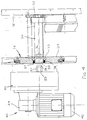
- a printing machine 10 for web W comprises a plurality of printing units 1 - 8 driven from a prime mover 12 through a common drive shaft 13.
- the prime mover 12 in the embodiment shown, also drives a folding unit 14. Whilst eight printing units are shown, additional printing units may be added as shown in broken lines at the lefthand end of the machine in Figs.1 and 2.
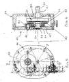
- Each printing unit includes a gearbox 15 having a casing 16 (see Fig.3) through which passes a section 13a of the drive shaft 13.
- the section 13a is journalled on bearings 17 in the casing 16.
- the gearbox casing 16 is mounted on a side plate 18 of the printing unit which rotatably supports a plurality of cylinders 19 - 22 for applying print to the web W.
- the shaft section 13a carries a bevel gear 23.
- the bevel gear 23 is slidably mounted on the shaft and keyed thereto, e.g., by splines, so that it can be moved axially along the shaft 13a by means of a fork shown diagrammatically at 24.
- Such axial movement of the bevel gear 23 permits the gear to be moved into and out of meshing engagement with a bevel gear 25 drivably connected to a gear wheel 26.
- the gear wheel 26 meshes with adjacent gears 27, 28 which in turn mesh with further gearing (not shown) to form a gear train which drives the cylinders of the printing unit.
- gearbox shown in Fig.3 is illustrated diagrammatically.
- One gear wheel 29 of the gear train is drivably connected to a shaft 30 which is journalled in a bearing 32 (see Fig.4) at its end adjacent the side plate 18 and is journalled at its opposite end in a bearing 33 in a section 34 of the gearbox casing 16.
- the left hand end of the shaft 30 is formed with a hexagonal socket 35 which terminates at a short cylindrical blind bore 36.
- An oil seal 37 is disposed between the outer periphery of the shaft 30 and a counterbore 38 formed in the casing section 34.
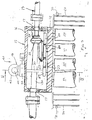
- a drive system 40 including an auxiliary drive unit 41 is carried by the gearbox casing 16 as shown in Fig.3.
- the drive unit is shown spaced from the casing 16.
- the drive unit 41 comprises an electric motor 42 which provides drive input to a reduction drive unit 43 via an initial step down unit 44.
- the step down unit 44 has an output shaft 45 which, as shown in Fig.6, is drivably connected to a spur gear 46.
- the spur gear 46 meshes with a larger gear wheel 47 to provide a reduction drive ratio to a clutch armature 48 via an adapter 49.
- the armature 48 forms part of a magnetic clutch generally indicated at 50, the clutch including a rotor 52 drivably connected to a drive output shaft 53.
- the output shaft 53 is journalled in bearings 54, 55 in a casing 56 of the reduction unit 43.
- the shaft 53 is formed with a hexagonal section 57 of complementary shape to the socket 35 and is formed at its extreme right hand end as a spigot 58 which is locatable in the blind bore 36 when the auxiliary drive unit is mounted on the casing 16.
- the gear 47 is rotatably supported on the shaft 53 by a bearing 59.
- Each of the printing units 1 - 8 is provided with a plurality of guards 59, 60.
- the guards are movable, typically pivotable, from closed operative positions to open inoperative positions and are associated with a sensing circuit 69.
- the sensing circuit is common to all units of the machine and includes series connected microswitches 70 associated with the guards of the printing units. If any one guard is opened when the printing machine is running, the sensing circuit, constituting the aforesaid drive inhibiting means, is broken and the whole of the machine (and not simply the individual unit concerned) will stop.
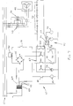
- Fig.7 shows a control circuit 61 used to operate the auxiliary drive unit 40.
- a three phase supply 62 provides an input to a main transformer 63 having an output side providing first and second outputs 64, 65.
- the first output 64 is connected to a rectifier 66 which provides direct current for energising the clutch 50.
- the second output 65 is connected to a relay 67 and other components of the circuit 61 as now described.
- a microswitch 68 is associated with the bevel gear 23 and is an open condition when the bevel gears 23, 25 mesh as shown in Fig.3 and moves to a closed condition when the bevel gear 23 is moved axially to disengage the bevel gear 25. In the disengaged position, drive from the drive shaft 13 to the bevel gear 25 will be interrupted and drive to the printing unit will cease.
- a timer 69 will operate relay 67 so as to close switches SW1 - SW4 thereof.
- Closure switch SW1 bridges switches 70 associated with guards of the printing unit.
- Closure of switch SW2 places the circuit for energising clutch 50 into a "ready” condition
- closure of switch SW3 places a motor switching circuit 72 in a "ready” condition
- closure of switch SW4 illuminates an indicator lamp 73 to show to an operator that the guards can be opened on that particular unit.
- the bevel gear wheel 23 is in its non-meshing position so that no drive is transmitted to the printing unit from the shaft 13.
- the motor 42 is drivable by the three phase supply 62 via a forward drive switch 73 or a reverse drive switch 74.
- a forward/reverse (F, R) drive selector switch 75 is provided which permits current to be directed to either one of the switches 73, 74 via respective thermistors 76, 77.
- the switch 75 also has an intermediate open circuit position S where neither F nor R is selected.
- a push button switch 78 is provided which, when closed causes, the motor drive circuit 72 and the clutch 50 to be energised. If desired, the switches 75, 78 could be provided on an extension lead for remote control of the motor 42.
- All of the printing units 1 - 8 or selected individual units can be provided with a drive system 40 in accordance with the invention. Where the printing machine is being run by utilising only, say, units 4 - 8 units 1, 2 and 3 will also be running in view of the common drive shaft 13. If units 1, 2 and 3 are provided with drive systems 40 in accordance with the invention, all or any one of them can be serviced whilst printing units 4 to 8 are still operating.
- the bevel gear 23 of that printing unit is moved out of mesh with bevel gear 25 so that switch 68 operates.
- the timer 69 is set so that the relay 67 will operate after the rotary parts of the printing unit 1 have come to a halt.
- the relay 67 then operates to bridge out the switches 70 and simultaneously illuminate the indicator 73 so that an operator knows that any one of the guards can be opened without bringing the printing units 4 - 8 to a halt. So far, the invention has performed as an isolating system by which the printing unit 1 can be isolated from the remainder of the machine. Servicing work can now be performed on the printing unit 1.
- the forward and reverse selector switch 75 is operated appropriately and the push button switch 78 is then closed to rotate the cylinders.
- the appropriate thermistor 76, 77 ensures that current will not pass to the electric motor 42 before the clutch 50 has been fully energised. Once current passes through the motor 42, the reduction drive through the clutch 50 will turn the cylinders 19 - 22 very slowly in the direction selected.
- printing unit as used herein embraces also perforating unit, embossing unit folding unit or like unit used in the printing trade.
- a slave motor unit 12a (Fig.1) which shares power with and rotates at the same speed as the prime mover 12 can be used as an additional drive for the shaft 13. Two or more such slave motor units could be provided.
Landscapes
- Engineering & Computer Science (AREA)
- Mechanical Engineering (AREA)
- Inking, Control Or Cleaning Of Printing Machines (AREA)
Applications Claiming Priority (2)
| Application Number | Priority Date | Filing Date | Title |
|---|---|---|---|
| GB909019466A GB9019466D0 (en) | 1990-09-06 | 1990-09-06 | A drive or isolating system for a printing machine |
| GB9019466 | 1990-09-06 |
Publications (1)
| Publication Number | Publication Date |
|---|---|
| EP0478165A1 true EP0478165A1 (de) | 1992-04-01 |
Family
ID=10681763
Family Applications (1)
| Application Number | Title | Priority Date | Filing Date |
|---|---|---|---|
| EP91308143A Withdrawn EP0478165A1 (de) | 1990-09-06 | 1991-09-05 | Ein Antriebs- oder Trennsystem für eine Rollenrotationsmaschine |
Country Status (3)
| Country | Link |
|---|---|
| EP (1) | EP0478165A1 (de) |
| CA (1) | CA2050841A1 (de) |
| GB (1) | GB9019466D0 (de) |
Cited By (1)
| Publication number | Priority date | Publication date | Assignee | Title |
|---|---|---|---|---|
| NL9302039A (nl) * | 1993-11-25 | 1995-06-16 | Crown Gear Bv | Verstelbare aandrijfinrichting. |
Citations (3)
| Publication number | Priority date | Publication date | Assignee | Title |
|---|---|---|---|---|
| GB245368A (en) * | 1925-07-22 | 1926-01-07 | Hoe & Co R | Improvements in safety devices applicable for use with printing machine cylinders |
| GB970613A (en) * | 1962-06-08 | 1964-09-23 | Planeta Veb Druckmasch Werke | Improvements in safety circuits for electrically-driven machines |
| EP0328741A2 (de) * | 1988-02-19 | 1989-08-23 | Rockwell International Corporation | Antriebsvorrichtung zum zentimeterweisen Vorrücken |
-
1990
- 1990-09-06 GB GB909019466A patent/GB9019466D0/en active Pending
-
1991
- 1991-09-05 EP EP91308143A patent/EP0478165A1/de not_active Withdrawn
- 1991-09-06 CA CA 2050841 patent/CA2050841A1/en not_active Abandoned
Patent Citations (3)
| Publication number | Priority date | Publication date | Assignee | Title |
|---|---|---|---|---|
| GB245368A (en) * | 1925-07-22 | 1926-01-07 | Hoe & Co R | Improvements in safety devices applicable for use with printing machine cylinders |
| GB970613A (en) * | 1962-06-08 | 1964-09-23 | Planeta Veb Druckmasch Werke | Improvements in safety circuits for electrically-driven machines |
| EP0328741A2 (de) * | 1988-02-19 | 1989-08-23 | Rockwell International Corporation | Antriebsvorrichtung zum zentimeterweisen Vorrücken |
Cited By (1)
| Publication number | Priority date | Publication date | Assignee | Title |
|---|---|---|---|---|
| NL9302039A (nl) * | 1993-11-25 | 1995-06-16 | Crown Gear Bv | Verstelbare aandrijfinrichting. |
Also Published As
| Publication number | Publication date |
|---|---|
| CA2050841A1 (en) | 1992-03-07 |
| GB9019466D0 (en) | 1990-10-24 |
Similar Documents
| Publication | Publication Date | Title |
|---|---|---|
| US4449416A (en) | Transmission control system | |
| EP0377848B1 (de) | Elektrisch betätigte X-Y-Schalteinrichtung | |
| DE3907841C2 (de) | ||
| US3038352A (en) | Dual speed trim actuator mechanism and control system for a control surface of an aircraft | |
| US4858481A (en) | Position controlled linear actuator | |
| ES2149653A1 (es) | Dispositivo y procedimiento para el accionamiento de una caja de cambios. | |
| US4892036A (en) | Combination collection and folding cylinder system | |
| DE3509905A1 (de) | Drehmomentuebertragungsvorrichtung | |
| EP0327975B1 (de) | Automatische Reinigungseinrichtung für eine Bahnführungsrolle | |
| US4394835A (en) | Drive for rotary-roller offset printing machines | |
| US2649813A (en) | Power and manually operated gear shift | |
| US5790969A (en) | Switch activated limp-home circuit for a power transmission | |
| DE2461421C3 (de) | Sicherheitsgangschaltung an einem Schneeräumfahrzeug, insbesondere einer Schneefräse oder Schneeschleuder | |
| EP0478165A1 (de) | Ein Antriebs- oder Trennsystem für eine Rollenrotationsmaschine | |
| JPS5816958A (ja) | パワ−ステアリング装置 | |
| GB1593207A (en) | Web printing press | |
| US3129607A (en) | Drive unit and control | |
| GB2394261A (en) | Shift mechanism having a rotating drum | |
| US2788675A (en) | Preselect automatic change speed gear shift | |
| EP0328741B1 (de) | Antriebsvorrichtung zum zentimeterweisen Vorrücken | |
| US4478320A (en) | Overload-responsive clutch apparatus for selective connection of two drive shafts to a single driven shaft | |
| US2683848A (en) | Overload control for motors | |
| US5535864A (en) | Transmission for a working vehicle | |
| US2611886A (en) | Power-transmission mechanism | |
| US2356160A (en) | Printing machine drive |
Legal Events
| Date | Code | Title | Description |
|---|---|---|---|
| PUAI | Public reference made under article 153(3) epc to a published international application that has entered the european phase |
Free format text: ORIGINAL CODE: 0009012 |
|
| AK | Designated contracting states |
Kind code of ref document: A1 Designated state(s): BE CH DE DK ES FR GB LI NL SE |
|
| 17P | Request for examination filed |
Effective date: 19920923 |
|
| 17Q | First examination report despatched |
Effective date: 19940119 |
|
| STAA | Information on the status of an ep patent application or granted ep patent |
Free format text: STATUS: THE APPLICATION IS DEEMED TO BE WITHDRAWN |
|
| 18D | Application deemed to be withdrawn |
Effective date: 19940531 |