EP0478217B1 - Bewegungsabhängige Videosignalverarbeitung - Google Patents
Bewegungsabhängige Videosignalverarbeitung Download PDFInfo
- Publication number
- EP0478217B1 EP0478217B1 EP91308521A EP91308521A EP0478217B1 EP 0478217 B1 EP0478217 B1 EP 0478217B1 EP 91308521 A EP91308521 A EP 91308521A EP 91308521 A EP91308521 A EP 91308521A EP 0478217 B1 EP0478217 B1 EP 0478217B1
- Authority
- EP
- European Patent Office
- Prior art keywords
- motion vector
- motion
- video signal
- blocks
- sum
- Prior art date
- Legal status (The legal status is an assumption and is not a legal conclusion. Google has not performed a legal analysis and makes no representation as to the accuracy of the status listed.)
- Expired - Lifetime
Links
- 230000033001 locomotion Effects 0.000 title claims description 346
- 238000012545 processing Methods 0.000 title description 9
- 230000001419 dependent effect Effects 0.000 title description 3
- 239000013598 vector Substances 0.000 claims description 285
- 238000012360 testing method Methods 0.000 claims description 59
- 238000000034 method Methods 0.000 claims description 37
- 230000000750 progressive effect Effects 0.000 description 17
- 239000003638 chemical reducing agent Substances 0.000 description 12
- 230000008569 process Effects 0.000 description 11
- 238000006243 chemical reaction Methods 0.000 description 10
- 230000000875 corresponding effect Effects 0.000 description 10
- 230000000694 effects Effects 0.000 description 8
- 230000009467 reduction Effects 0.000 description 7
- 238000010586 diagram Methods 0.000 description 6
- 230000004048 modification Effects 0.000 description 6
- 238000012986 modification Methods 0.000 description 6
- 230000002596 correlated effect Effects 0.000 description 4
- 230000003247 decreasing effect Effects 0.000 description 4
- 238000011946 reduction process Methods 0.000 description 4
- 230000003044 adaptive effect Effects 0.000 description 3
- 230000008901 benefit Effects 0.000 description 3
- 238000001514 detection method Methods 0.000 description 3
- 238000013507 mapping Methods 0.000 description 3
- 230000002123 temporal effect Effects 0.000 description 3
- 230000008859 change Effects 0.000 description 2
- 239000011159 matrix material Substances 0.000 description 2
- 238000013459 approach Methods 0.000 description 1
- 230000009286 beneficial effect Effects 0.000 description 1
- 230000000052 comparative effect Effects 0.000 description 1
- 230000001934 delay Effects 0.000 description 1
- 238000009795 derivation Methods 0.000 description 1
- 238000006073 displacement reaction Methods 0.000 description 1
- 238000001914 filtration Methods 0.000 description 1
- 239000000463 material Substances 0.000 description 1
- 238000005259 measurement Methods 0.000 description 1
- 230000007246 mechanism Effects 0.000 description 1
- 230000000737 periodic effect Effects 0.000 description 1
- 230000008439 repair process Effects 0.000 description 1
- 230000010076 replication Effects 0.000 description 1
- 230000003068 static effect Effects 0.000 description 1
- 239000011800 void material Substances 0.000 description 1
Images


Classifications
-
- H—ELECTRICITY
- H04—ELECTRIC COMMUNICATION TECHNIQUE
- H04N—PICTORIAL COMMUNICATION, e.g. TELEVISION
- H04N7/00—Television systems
- H04N7/01—Conversion of standards, e.g. involving analogue television standards or digital television standards processed at pixel level
- H04N7/0135—Conversion of standards, e.g. involving analogue television standards or digital television standards processed at pixel level involving interpolation processes
- H04N7/014—Conversion of standards, e.g. involving analogue television standards or digital television standards processed at pixel level involving interpolation processes involving the use of motion vectors
Definitions
- This invention relates to motion dependent video signal processing. More particularly, the invention relates to methods of deriving motion vectors representing motion between fields or frames of a video signal, and to video standards converters using such methods. Still more particularly, but not exclusively, the invention relates to the type of video standards converter generally known as and referred to herein as a down converter.
- Video standards converters are well known devices used to convert video signals from one standard to another, for example, from a 625 lines per frame, 50 fields per second standard to a 525 lines per frame, 60 fields per second standard. Video standards conversion cannot be achieved satisfactorily merely by using simple linear interpolation techniques, because of the temporal and vertical alias which is present in a video signal. Thus, simple linear interpolation produces unwanted artefacts in the resulting picture, in particular, the pictures are blurred vertically and judder temporally.
- video standards converters should use adaptive techniques to switch the parameters of a linear interpolator in dependence on the degree of movement in the picture represented by the incoming video signal.
- the present invention is particularly concerned with modifying the algorithms used in the motion vector selection such that the amount of hardware required can be reduced and also with widening the range of video standards converters in which the methods can be used to include down converters operable in real time.
- EP-A-0 294 961 discloses a motion vector selection system in which a plurality of motion vectors are identified and then a selection between these motion vectors made based upon a sum of absolute differences in pixel values.
- a method of deriving motion vectors representing motion between successive fields or frames of an input video signal from which a standards-converted output video signal is to be derived by motion compensated interpolation including the steps of: deriving a plurality of motion vectors for each pixel of each field or frame of said output video signal; and testing each said motion vector by deriving the sum of absolute luminance differences of corresponding pixels in blocks of pixels in the two fields or frames of said input video signal temporally nearest a field or frame of said output video signal, which blocks are pointed to by the motion vector under test; characterised by centre-weighting said sum of absolute luminance differences if the magnitude of said motion vector under test is less than a predetermined value; and selecting from said plurality of motion vectors, the motion vector which results in the minimum of said sum, subject to said applied centre-weighting, of absolute luminance differences.
- a motion compensated video standards converter comprising:
- motion compensated video standards converter to be described is particularly intended for use as a down converter for converting a high definition video signal (HDVS) having 1125 lines per frame and 60 fields per second, to a standard PAL television signal having 625 lines per frame and 50 fields per second.
- HDVS high definition video signal
- standard PAL television signal having 625 lines per frame and 50 fields per second.
- the invention is not limited in this respect, and that the standards converter can readily be adapted to effect conversions between other standards.
- FIG. 1 is a block diagram of the standards converter.
- the standards converter comprises an input terminal 1 to which an input video signal is supplied.
- the input terminal 1 is connected to a progressive scan converter 2 in which the input video fields are converted into video frames which are supplied to a direct block matcher 3 wherein correlation surfaces are created.
- correlation surfaces are analyzed by a motion vector estimator 4, which derives and supplies motion vectors to a motion vector reducer 5, wherein the number of motion vectors for each pixel is reduced, before they are supplied to a motion vector selector 6, which also receives an output from the progressive scan converter 2.
- any irregularity in the selection of the motion vectors by the motion vector selector 6 is removed by a motion vector post processor 7, from which the processed motion vectors are supplied to and control an interpolator 8 which also receives an input from the progressive scan converter 2.
- the output of the interpolator 8, which is a standards-converted and motion-compensated video signal is supplied to an output terminal 9.
- the progressive scan converter 2 produces output frames at the same rate as the input fields.
- Figure 2 which shows a sequence of consecutive lines in a sequence of consecutive fields, the crosses representing lines present in the input fields and the squares representing interpolated lines
- each output frame will contain twice the number of lines as an input field, the lines alternating between lines from the input video signal and lines which have been interpolated by one of the methods to be described below.
- the interpolated lines can be regarded as an interpolated field of the opposite polarity to the input field, but in the same temporal position.
- Progressive scan conversion is preferably carried out, for two main reasons; firstly, to make the following direct block matching process easier, and secondly in consideration of the final output video format. Concerning block matching, this is used to obtain an accurate estimation of the horizontal and vertical motion between two successive video fields, as described in more detail below. However, if an interlaced video signal is used for direct block matching, problems can arise.
- the progressive scan converted frames can be used as a fall-back in the case where motion compensated standards conversion is deemed to be producing unacceptable results, for example, where the motion is too diverse to be analyzed satisfactorily or at a scene change. In that case the use of the nearest progressive scan converted frame as the required output frame can produce reasonably acceptable results.
- Progressive scan conversion can be carried out in a number of ways, such as by previous field replacement, median filtering in which three spatially consecutive lines are examined (temporally these three lines will come from two consecutive fields), or a motion compensated technique which utilizes multi-gradient motion detection followed by multi-direction linear interpolation.
- the preferred method is motion adaptive progressive scan conversion, the steps of which are indicated in the block diagram of Figure 3.
- the concept is to use inter-field interpolation in wholly static picture areas to retain as much vertical information as possible, and to use intra-field interpolation when significant motion is present. This also aids smooth portrayal of motion.
- the frames of video derived by the progressive scan converter 2 are used to derive motion vectors.
- the estimation of motion vectors consists of two steps. Firstly, correlation surfaces are generated by correlating search blocks from consecutive frames. Then, having obtained these correlation surfaces, they have to be examined to determine the position or positions at which correlation is best. Several different methods of obtaining a correlation surface exist, and in the present case the method used is direct block matching.
- the direct block matcher 3 operates as follows. Two blocks, respectively comprising a rectangular array of pixels from consecutive frames of the progressive scan converted video signal are correlated to produce a correlation surface from which a motion vector is derived.
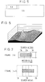
- a small block called a search block of size 32 pixels by 23 lines is taken from a frame as shown in Figure 4.
- a larger block called a search area of size 128 pixels by 69 lines is taken from the next frame.
- the search block (SB) is then placed in each possible position in the search area (SA) as shown in Figure 5, and for each location the sum of the absolute difference of pixel luminance levels between the two blocks is calculated. This value is then used as the height of the correlation surface at the point at which it was derived. It can then be used in conjunction with other similarly derived values for each possible location of the search block in the search area to obtain a correlation surface, an example of which is shown in Figure 6. For clarity the surface is shown inverted, and as it is in fact the minimum that is required, the required point in Figure 6 is the main peak.
- the size of the search block is selected by examining the minimum size of an object that may require motion compensation.
- PAL 625 lines per frame 50 fields per second signals a search block of 16 pixels by 8 lines has been found suitable for tracking a small object without allowing any surrounding information not within the object, but still within the search block, to affect the tracking of the object.
- This approach has therefore been adopted in the present embodiment, but modified to take account of the different numbers of active pixels per line, active lines per frame, and aspect ratio of a HDVS as compared with PAL 625/50.
- the comparative figures, the HDVS being put first, are as follows; 1920 (720) active pixels per line, 1035 (575) active lines per frame, 9:16 (3:4) aspect ratio.
- This technique of causing the search block to grow is not only advantageous for tracking large objects. It can also help to track the movement of an object having the shape of a regular pattern of a periodic nature.
- the search block, and the search area can both be grown horizontally or vertically, or indeed in both directions, if the correlation surface suggests it.
- the motion vector estimator 4 ( Figure 1) uses motion vector estimation algorithms to detect the minimum point on each correlation surface. This represents the point of maximum correlation between the search block and the search area, and hence indicates the probable motion between them.
- the displacement of this minimum on the correlation surface with respect to the origin, in this case the centre of the surface is a direct measurement, in terms of pixels per frame, of the motion.
- the detection of the minimum point on the correlation surface is sufficient to determine accurately the motion between the search block and the search area.
- the use of small search blocks improves the detection of motion and the accuracy of motion estimation, but unfortunately small single search blocks are unable to detect motion in a number of circumstances which will now be described.
- Figure 7 shows an object with motion vectors (5, 0) straddling three search blocks 1A, 2A and 3A in a frame (t).
- a correlation surface shown in Figure 8 results showing a minimum at (5, 0).
- the search block 2A is correlated with its respective search area 2B
- the correlation surface shown in Figure 9 is produced, in which the search block 2A correlates with the search area 2B at every point in the y-axis direction. There is therefore no single minimum in the correlation surface, and hence the motion between the search block 2A and the search area 2B cannot be determined.
- the search block 2A is grown such that it encompasses all three of the original search blocks 1A, 2A and 3A.
- the grown search block 2A is correlated with a search area covering the original search areas 1B, 2B and 3B, the resulting correlation surface is as shown in Figure 10.
- This example illustrates the need for some unique feature in the source video, in order accurately to detect motion.
- the search blocks 1A and 3A both had unique vertical and horizontal features, that is the edges of the object, and hence motion could be determined.
- the search block 2A had a unique vertical feature, but no unique horizontal feature, and hence horizontal motion could not be determined.
- growing the search block is beneficial when noise in the source video is considered.
- search blocks are grown.
- the area of the search block 2A to encompass the areas of the search blocks 1A and 3A, and to produce the resulting correlation surface.
- the resulting correlation surfaces are produced directly by adding together the elements of the three correlation surfaces corresponding to the search blocks 1A, 2A and 3A.
- each correlation surface is considered as a matrix of point magnitudes
- the correlation surface of the enlarged search block 2A is the matrix addition of the correlation surface of the original search blocks 1A, 2A and 3A.
- the area of the search block 2A could also be grown vertically by adding correlation surfaces of the search blocks above and below, whilst if the search block 2A is to be grown both horizontally and vertically, then the four neighbouring diagonal correlation surfaces have to be added as well. From this it will be seen that the actual process of growing a search block to encompass neighbouring search blocks is relatively easy, the more difficult process being to decide when growing should the place, and which neighbouring search blocks should be encompassed. Basically, the answer is that the area of the search blocks should be grown until a good minimum or good motion vector is detected. It is therefore necessary to specify when a motion vector can be then to be a good motion vector, and this can in fact be deduced from the examples given above.
- a good minimum is the point of smallest magnitude on the correlation surface for which the difference between it and the magnitude of the next smallest point exceeds a given value.
- This given value is known as the threshold value, and hence this test is referred to herein as the threshold test.
- next smallest point is prevented from originating from within the bounds of a further test, described below, and referred to herein as the rings test.
- the next smallest point is prevented from originating from a point within three pixels of the point in question.
- the correlation surface of Figure 9 would have failed the threshold test; the search area 2A is therefore grown and, given a suitable threshold value, the correlation surface of Figure 10 will pass the threshold test.
- the threshold test can also be used to cause growing in the example described above with reference to Figures 11 and 12. Prior to growing the search block, the correct minimum is undetectable, due to the closely similar magnitudes of the surrounding points. Given a suitable threshold value, however, the correlation surface will fail the threshold test, and the search block will be grown. As a result, it will then be possible to detect the minimum among the other spurious points.
- the use of a threshold is a subjective test, but the correct threshold for the correlation surface under test can be selected by normalizing the threshold as a fraction of the range of magnitudes within the correlation surface. This also lessens the effect of, for example the contrast of the video source.
- the rings test referred to briefly above, and which is far less subjective, will now be further described.
- the basis of the rings test is to assume that a good minimum (or maximum) will have points of increasing (or decreasing) magnitudes surrounding it.
- Figure 13 illustrates this assumption, showing a minimum at (0, 0) where the surrounding three rings of points have decreasing mean magnitude. This is as opposed to the correlation surface shown in Figure 14, where the rings, and in particular the second inner-most ring, are not of decreasing mean magnitude.
- the criteria for a good minimum as defined by the rings test is that the average slope is monotonic. Therefore for a pre-defined number of rings of points surrounding the minimum in question, the mean magnitude of each ring when moving from the innermost ring outwards, must be greater than that of the previous ring.
- the rings test compares mean, and not absolute, magnitudes, it is far less subjective than the threshold test, and indeed the only variable in the rings test is the number of rings considered.
- this correlation surface resulted where there was a unique vertical feature, but no unique horizontal feature. This is mirrored in the correlation surface by the minimum running horizontally across the correlation surface, due to the multiple correlations in this direction. From this it can be deduced that the search block should be grown horizontally. Conversely, should a line of multiple correlations run vertically, this would indicate the need to grow the search block vertically, whilst a circular collection of multiple correlations would indicate a need to grow the search block both horizontally and vertically.
- a quantitave measure of the shape of the correlation surface is required in order to determine in which direction the search block should be grown. This measure is determined as follows. Firstly, a threshold is determined. Any point on the correlation surface below the threshold is then considered. This threshold, like that used in the threshold test, is normalized as a fraction of the range of magnitudes within the correlation surface. Using this threshold, the points on the correlation surface are examined in turn in four specific sequences. In each, the point at which the correlation surface value falls below the threshold is noted. These four sequences are illustrated diagrammatically in Figure 15 in which the numbers 1, 2, 3 and 4 at the top, bottom, left and right refer to the four sequences, and the hatched area indicates points which fall below the threshold:
- the locations of the four resulting points A, B, C and D are used to calculate the two dimensions X and Y indicated in Figure 15, these dimensions X and Y indicating the size of the hatched area containing the points falling below the threshold value.
- these dimensions X and Y indicating the size of the hatched area containing the points falling below the threshold value.
- the shape is considered to be circular, and the search block is grown in both directions.
- the dimension X is greater than the dimension Y, and hence the search block is grown in the x or horizontal direction.
- the growing of the search block continues until one or more growth limitations is reached. These limitations are: that the minimum in the correlation surface passes both the threshold test and the rings test; that the edge of the video frame is reached; or that the search block has already been grown a predetermined number of times horizontally and vertically. This last limitation is hardware dependent. That is to say, it is limited by the amount of processing that can be done in the available time. In one specific embodiment of apparatus according to the present invention, this limit was set at twice horizontally and once vertically.
- the minimum in the correlation surface passes both the threshold test and the rings test, then it is assumed that a good motion vector has been determined, and can be passed to the motion vector reducer 5 ( Figure 1). However, if the edge of the frame is reached or the search block has already been grown a predetermined number of times both horizontally and vertically, then it is assumed that a good motion vector has not been determined for that particular search block, and instead of attempting to determine a good motion vector, the best available motion vector is determined by weighting.
- the correlation surface is weighted such that the selection of the best available motion vector is weighted towards the stationary, that is the centre, motion vector. This is for two reasons, firstly, if the search block, even after growing, is part of a large plain area of source video, it will not be possible to detect a good motion vector. However, since the source video is of a plain area, a stationary motion vector will lead to the correct results in the subsequent processing. Secondly, weighting is designed to reduce the possibility of a seriously wrong motion vector being passed to the motion vector reducer 5 ( Figure 1). This is done because it is assumed that when a good motion vector cannot be determined, a small incorrect motion vector is preferable to a large incorrect motion vector.
- Figure 16 shows an example of how the weighting function can be applied to the correlation surface.
- the weight applied to a given point on the correlation surface is directly proportional to the distance of that point from the stationary, centre motion vector.
- the magnitude of the point on the correlation surface is multiplied by the weighting factor.
- the gradient of the weighting function may be such that points plus or minus 32 pixels from the centre, stationary motion vector are multiplied by a factor of three.
- the weighting function is an inverted cone which is centred on the centre, stationary motion vector.
- the correlation surface After the correlation surface has been weighted, it is again passed through the threshold test and the rings test. If a minimum which passes both these tests is determined, then it is assumed that this is a good motion vector, and it is flagged to indicate that it is a good motion vector, but that weighting was used. This flag is passed, together with the motion vector to the motion vector reducer 5 ( Figure 1). If on the other hand, neither a good motion vector nor a best available motion vector can be determined, even after weighting, then a flag is set to indicate that any motion vector passed to the motion vector reducer 5 ( Figure 1) for this search block is a bad motion vector. It is necessary to do this because bad motion vectors must not be used in the motion vector reduction process, but must be substituted as will be described below.
- the operation of the motion vector estimator 4 is to derive from the correlation surface generated by the direct block matcher 3 ( Figure 1), the point of best correlation, that is the minimum. This minimum is then subjected to the threshold test and the rings test, both of which the minimum must pass in order for it to be considered to represent the motion of the search block.
- the threshold used in the threshold test and the rings test may be either absolute values or fractional values. If the minimum fails either test, then the search block is grown, a new minimum is determined, and the threshold test and the rings test re-applied. The most effective direction in which to grow the search block is determined from the shape of the correlation surface.
- each search block is assumed to be 32 pixels by 23 lines, which can be shown to lead to a possible maximum of 2451 motion vectors.
- the choice of the search block size is a compromise between maintaining resolution and avoiding an excessive amount of hardware. If all these motion vectors were passed to the motion vector selector 6, the task of motion vector selection would not be practicable, due to the amount of processing that would be required.
- the motion vector reducer 5 is provided between the motion vector estimator 4 and the motion vector selector 6.
- the motion vector reducer 5 takes the motion vectors that have been generated by the motion vector estimator 4 and presents the motion vector selector 6 with only, for example, four motion vectors for each search block in the frame, including those in border regions, rather than all the motion vectors derived for that frame. The effect of this is two-fold. Firstly, this makes it much easier to choose the correct motion vector, so long as it is within the group of four motion vectors passed to the motion vector selector 6. Secondly, however, it also means that if the correct motion vector is not passed as one of the four, then the motion vector selector 6 is not able to select the correct one. It is therefore necessary to try to ensure that the motion vector reducer 5 includes the correct motion vector amongst those passed to the motion vector selector 6.
- sample block' refers to a block in a frame of video in which each pixel is offered the same four motion vectors by the motion vector reducer 5.
- a sample block is the same as a search block before the search block has been grown, and in a frame of video the initial positions of the sample blocks and the search blocks are the same.
- the motion vector reducer 5 receives the motion vectors and the flags from the motion vector estimator 4 ( Figure 1) and determines the quality of the motion vectors by examining the flags. If the motion vector was not derived from an ambiguous surface, that is there is a high degree of confidence in it, then it is termed a good motion vector, but if a certain amount of ambiguity exists, then the motion vector is termed a bad motion vector. In the motion vector reduction process, all motion vectors classed as bad motion vectors are ignored, because it is important that no incorrect motion vectors are ever passed to the motion vector selector 6 ( Figure 1), in case a bad motion vector is selected thereby. Such selection would generally result in a spurious dot in the final picture, which would be highly visible.
- Each of the motion vectors supplied to the motion vector reducer 5 ( Figure 1) was obtained from a particular search block, and hence a particular sample block, the position of these being noted together with the motion vector. Because any motion vectors which have been classed as bad motion vectors are ignored, not all sample blocks will have a motion vector derived from the search block at that position.
- the motion vectors which have been classed as good motion vectors, and which relate to a particular search block, and hence a particular sample block, are called local motion vectors, because they have been derived in the area from which the sample block was obtained.
- another motion vector reduction process counts the frequency at which each good motion vector occurs, with no account taken of the actual positions of the search blocks that were used to derive them.
- a simple way of reducing the number of common motion vectors is to use the three most frequent common motion vectors and disregard the remainder.
- the three most frequent common motion vectors are often those three motion vectors which were initially within plus or minus one pixel motion of each other vertically and/or horizontally. In other words, these common motion vectors were all tracking the same motion with slight differences between them, and the other common motion vectors, which would have been disregarded, were actually tracking different motions.
- the strategy actually adopted is first to take the three most frequently occurring common motion vectors and check to see if the least frequent among them is within plus or minus one pixel motion vertically and/or plus or minus one pixel motion horizontally of either of the other two common motion vectors. If it is, then it is rejected, and the next most frequently occurring common motion vector is chosen to replace it. This process is continued for all of the most frequently occurring common motion vectors until there are either three common motion vectors which are not similar to each other, or until there are three or less common motion vectors left.
- Region A comprises sample blocks which are totally surrounded by other sample blocks and are not near the picture boundary.
- Region B contains sample blocks which are partially surrounded by other sample blocks and are not near the picture boundary.
- region C contains sample blocks which are near the picture boundary.
- the motion vector reduction algorithm to be used for each of these regions is different. These algorithms will be described below, but firstly it should be reiterated that there exist good motion vectors for some of the sample blocks in the frame of video, and additionally there are also three global motion vectors which should represent most of the predominant motion in the scene. A selection of these motion vectors is used to pass on three motion vectors together with the stationary motion vector for each sample block.
- Figure 18 illustrates diagrammatically motion vector reduction in the region A. This is the most complex region to deal with, because it has the largest number of motion vectors to check.
- Figure 18 shows a central sample block which is hatched, surrounded by other sample blocks a to h. Firstly, the locally derived motion vector is examined to see if it was classed as a good motion vector. If it was, and it is also not the same as the stationary motion vector, then it is passed on. However,if it fails either of these tests, it is ignored. Then the motion vector associated with the sample block d is checked to see if it was classed as a good motion vector.
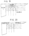
- Figure 19 illustrates motion vector reduction in the region B.
- Sample blocks in the region B are the same as those in the region A, except that they are not totally surrounded by other sample blocks.
- the process applied to these sample blocks is exactly the same as those for the region A, except that it is not possible to search in all the surrounding sample blocks.
- the hatched sample block in Figure 19 were displaced two positions to the left, then it will be seen that there would only be three adjacent surrounding blocks to be checked before resorting to global motion vectors.
- Figure 20 illustrates motion vector reduction in the region C. This is the most severe case, because the sample blocks neither have a locally derived motion vector nor do they have many surrounding sample blocks whose motion vectors could be used.
- the simplest way of dealing with this problem is simply to give the sample blocks in the region C the global motion vectors together with the stationary motion vector. However, this is found to produce a block-like effect in the resulting picture, due to the sudden change in the motion vectors presented for the sample blocks in the region C compared with adjoining sample blocks in the region B. Therefore a preferred strategy is to use for the sample blocks in the region C the sample motion vectors as those used for sample blocks in the region B, as this prevents sudden changes.
- each sample block in the region C is assigned the same motion vectors as that sample block in the region B which is physically nearest to it.
- each of the hatched sample blocks in the region C would be assigned the same motion vectors as the sample block a in the region B, and this has been found to give excellent results.
- the purpose of the motion vector selector 6 is to assign one of the four motion vectors supplied thereto to each individual pixel within the sample block. In this way the motion vectors can be correctly mapped to the outline of objects.
- the way in which this assignment is effected is particularly intended to avoid the possibility of the background surrounding fine detail from producing a better match than that produced by the correct motion vector.
- the motion vector selection makes use of two frames of pixels.
- One frame (input frame 1) is considered to be the reference frame, and the following frame to this (input frame 2) is also used.
- the output frame position then exists somewhere between the two input frames.
- For each output pixel position in the output frame the four possible motion vectors are tested. A line drawn through the output pixel position at the angle of the motion vector being tested will point to a position on the input frame 1 and a position on the input frame 2.
- the smallest of the four sums of absolute difference so derived indicates which of the four motion vectors gives the most accurate result for the output pixel position, and that motion vector is passed forward to the motion vector post processor 7 ( Figure 1). This is conveniently done by numbering the motion vectors 1 to 4 and identifying them by number except where they are actually to be used.
- the selected value is eight pixel lengths, which happens to be half the maximum possible magnitude, but some different value could be selected.
- the purpose of the modification is to prevent fine detail being lost by the use of the large (sixteen pixels by eight pixels) blocks, particularly where the motion is small, and the effect is to add weighting in the case of motion vectors of relatively small magnitude.
- the sum of absolute differences is derived as the sum of absolute differences for the smaller blocks (4 x 4) and the sum of absolute differences for the larger blocks (16 x 8), and the resulting sum of absolute differences is normalized (multiplied by 16 x 8 and divided by 16 x 8 plus 4 x 4) to permit level comparison with any sum of absolute differences derived using only the larger blocks (16 x 8) first described.
- the block sizes (16 x 8 and 4 x 4) are of course not critical, and can be varied to suit particular standards conversions or particular material to be converted.
- the circuit arrangement of Figure 22 comprises a reference read address generator 20, an address shift circuit 21, a mapping store 22, picture segment stores 23 and 24, block matchers 25 and 26, an adder 27, a normalizer 28, a selector 29, a store and comparison device 30, and an out of range detector 31, interconnected as shown and operating as will now be described.
- a corresponding segment of input frame 1 and input frame 2 is acquired in the picture segment stores 23 and 24 respectively, each segment being sufficiently more than one twelfth the number of lines in the frame to provide the overlap required in processing the blocks.
- the block matchers 25 and 26 start deriving the sums of absolute differences as described above, for each of the four motion vectors which have been stored in the mapping store 22. For convenience of operation both sums of absolute differences are derived from all magnitudes of motion vectors.
- the sum of absolute differences derived by the block matcher 25 is supplied directly to the selector 29, and the sum of absolute differences derived by the block matchers 25 and 26, added by the adder 27, and normalized by the normalizer 28 is likewise supplied to the selector 29, which selects which sum of absolute differences to supply to the store and comparison device 30 in dependence on a control signal supplied by the mapping store 22, and indicating whether the relevant motion vector is above or below the selected value.
- the store and comparison device 30 For each group of four motion vectors the store and comparison device 30 stores the sum of absolute differences corresponding to the first motion vector. On receiving the sum of absolute differences corresponding to the second motion vector it compares the two and stores the lower, and so on up to the sum of absolute differences corresponding to the fourth motion vector. The minimum of the four is then supplied as an output in the form of the number of the motion vector from which the minimum sum of absolute differences was derived. This output is supplied to the motion vector post processor 7 ( Figure 1).
- the purpose of the out of range detector 31 is to prevent the use in the block matchers 25 and 26 of blocks which lie wholly or partly outside the active picture region. If the larger block (16 x 8) overlaps or lies outside the edge of the active picture region then the smaller block (4 x 4) may be usable, but if the smaller block also overlaps or lies outside the edge of the active picture region then the current motion vector is rejected, because the comparison is void. This prevents an erroneous output pixel being generated.
- the out of range detector 31 generates a first control signal if either or both of the larger blocks (16 x 8) to be compared overlaps or goes outside the active picture region, and this first control signal forces the selector 29 to use the small block (4 x 4). If either or both of the smaller blocks to be compared overlaps or goes outside the active picture region, then the out of range detector 31 generates a second control signal which forces the motion vector under test to be replaced by the zero motion vector.
- Figure 23 shows one way of implementing this modification.
- a 4 x 4 block matcher 40 corresponding to the block matcher 26 of Figure 22, and is connected to seven 1-line-of-blocks delays 41 to 47 connected as shown.
- a 16 x 8 block match can then be derived as: ⁇ bm0, bm1, ..., bm7.
- FIG 24 shows another, somewhat simpler way of implementing the above modification.
- a 4 x 4 block matcher 50 corresponds to the block matcher 26 of Figure 22, and is connected to accumulators 51 and 52, a gate 53, a 1-block delay 54 and a 1-line-of-blocks delay 55 connected as shown.
- a gating signal is supplied via a terminal 56 to reset the accumulator 51.
- spurious motion vectors are assumed to exist at a point singularity, where a single pixel has a motion vector different from those of all the surrounding pixels; at a horizontal motion vector impulse, where three horizontally aligned pixels have a motion vector different from those of the surrounding pixels; at a vertical motion vector impulse, where three vertically aligned pixels have a motion vector different from those of the surrounding pixels; at a diagonal motion vector impulse, where three diagonally aligned pixels have a motion vector different from those of all the surrounding pixels; at a horizontal plus vertical motion vector impulse, where five pixels disposed in an upright cross have a motion vector different from those of all the surrounding pixels; and at a two-diagonal motion vector impulse, where five pixels arranged in a diagonal cross have a motion vector different from those of all the surrounding pixels.
- the finally selected motion vector for each pixel is supplied by the motion vector post processor 7 to the interpolator 8, together with the progressive scan converted frames at 60 frames per second from the progressive scan converter 2.
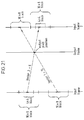
- the interpolator 8 is of relatively simple form using only two progressive scan converted frames, as indicated in Figure 25. Using the temporal position of the output frame relative to successive input frames, frame 1 and frame 2, and the motion vector for the pixel in the output frame, the interpolator 8 determines in known manner which part of the first frame should be combined with which part of the second frame and with what weighting to produce the correct output pixel value. In other words, the interpolator 8 adaptively interpolates along the direction of movement in dependence on the motion vectors to produce interlace scan fields corresponding to 25 frames per second.
- the interpolator 8 is a two-dimensional, vertical/horizontal, interpolator and the coefficients used for the interpolator 8 may be derived using the Remez exchange algorithm which can be found fully explained in 'Theory and application of digital signal processing', Lawrence R Rabiner, Bernard Gold. Prentice-Hall Inc., pages 136 to 140 and 227.
- Figure 25 shows diagrammatically the interpolation performed by the interpolator 8 (Figure 1) for three different cases.
- the first case, shown on the left, is where there are no uncovered or covered surfaces
- the second case, shown in the centre is where there is a covered surface
- the third case, shown on the right is where there is an uncovered surface.
- the interpolation uses only frame 1
- the interpolation uses only frame 2.
Landscapes
- Engineering & Computer Science (AREA)
- Multimedia (AREA)
- Signal Processing (AREA)
- Television Systems (AREA)
- Compression Or Coding Systems Of Tv Signals (AREA)
Claims (15)
- Verfahren zum Ableiten von Bewegungsvektoren, die eine Bewegung zwischen aufeinanderfolgenden Teil- oder Vollbildern eines Eingangsvideosignales repräsentieren, von dem ein standardumgesetztes Ausgangsvideosignal durch bewegungskompensierte Interpolation abgeleitet werden soll,mit folgenden Schritten:Ableiten mehrerer Bewegungsvektoren für jedes Pixel jedes Teil- oder Vollbildes des Ausgangsvideosignals,Testen jedes Bewegungsvektors durch Ableiten der Summe der absoluten Differenz der Leuchtdichte korrespondierender Pixel innerhalb von Pixelblöcken in den beiden Teil- oder Vollbildern des Eingangsvideosignales, die zeitlich gesehen einem Teil- oder Vollbild des Ausgangsvideosignales nächstgelegen sind, wobei die zu testenden Bewegungsvektoren auf die Blöcke weisen,
dadurch gekennzeichnet,daß die Mittel-gewichtete Summe der absoluten Differenzen der Leuchtdichte gebildet wird, wenn die Größe des zu testenden Bewegungsvektors kleiner ist, als ein vorbestimmter Wert, unddaß aus der Mehrzahl der Bewegungsvektoren derjenige ausgewählt wird, der das Minimum der Summe der absoluten Differenzen der Leuchtdichte ergibt, wenn die Summe mittelgewichtet wird. - Verfahren nach Anspruch 1,bei dem für jeden zu testenden Bewegungsvektor eine erste Summe von absoluten Differenzen der Leuchtdichte für jeweilige korrespondierende der Blöcke in zwei Teil- oder Vollbildern der Eingangsvideosignale abgeleitet wird, die in der Position in dem Teil- oder Vollbild zentriert sind, die durch den zu testenden Bewegungsvektor zugewiesen sind, wobei die Blöcke sich horizontal über n Pixel und vertikal über m Pixel erstrecken.
- Verfahren nach Anspruch 2,bei dem für jeden zu testenden Bewegungsvektor mit einer Größe, die kleiner ist als der vorbestimmte Wert, eine zweite Summe der absoluten Differenzen der Leuchtdichte abgeleitet wird für jeweilige korrespondierende weitere Blöcke in den zwei Teil- oder Vollbildern des Eingangsvideosignales, die auf die Position in dem Teil- oder Vollbild zentriert sind, wobei die weiteren Blöcke sich horizontal über p Pixel und vertikal über q Pixel erstrecken, wobei p kleiner als n ist und q kleiner als m ist, und die Mittel-Wichtung das Addieren der zweiten absoluten Summe der Leuchtdichten zu der ersten absoluten Summe der Leuchtdichten für den zu testenden Bewegungsvektor umfaßt.
- Verfahren nach Anspruch 3,bei dem die Summe aus der ersten absoluten Summe der Leuchtdichten und der zweiten absoluten Summe der Leuchtdichten vor dem Schritt des Auswählens normiert wird.
- Verfahren nach einem der vorhergehenden Ansprüche,bei dem die Bewegungsvektoren durch Vergleichen von Blöcken in einem ersten Teil- oder Vollbild eines Eingangsvideosignales mit einer Mehrzahl von Blöcken des Teil- oder Vollbildes des Eingangsvideosignales abgeleitet werden.
- Verfahren nach Anspruch 5,bei dem der Blockvergleich durch Vergleichen der Summen der Leuchtdichtepegel der Pixel in den jeweiligen miteinander verglichenen Blöcken bewirkt wird.
- Bewegungskompensierter Videostandardumsetzer, aufweisend:Mittel (3) zum Ableiten einer Mehrzahl von Bewegungsvektoren für jedes Pixel jedes Teil- oder Vollbildes eines standardumgesetzten Ausgangsvideosignals, wobei die Bewegungsvektoren eine Bewegung zwischen aufeinanderfolgenden Teil- oder Vollbildern eines Eingangsvideosignales repräsentieren, von dem das Ausgangsvideosignal durch bewegungskompensierte Interpolation abgeleitet werden soll, undein Mittel (25) zum Testen jedes Bewegungsvektors durch Ableiten der Summe der absoluten Differenz der Leuchtdichte korrespondierender Pixel in Pixeiblöcken in den zwei Teil- oder Vollbilder des Eingangsvideosignals, die zeitlich einem Teil- oder Vollbild des Ausgangsvideosignales nächstgelegen sind, wobei die zu testenden Bewegungsvektoren auf die Blöcke weisen,
gekennzeichnet durch,Mittel (26 bis 28) zum Bilden der mittelgewichteten Summe der absoluten Differenzen der Leuchtdichte, wenn die Größe des zu testenden Bewegungsvektors kleiner ist als ein vorbestimmter Wert, undMittel (29) zum Auswählen aus der Mehrzahl der Bewegungsvektoren desjenigen Bewegungsvektors, der das Minimum der Summe der absoluten Differenzen der Leuchtdichte ergibt, wenn die Summe mittelgewichtet wird. - Umsetzer nach Anspruch 7,bei dem für jeden zu testenden Bewegungsvektor eine erste Summe von absoluten Differenzen der Leuchtdichte für jeweilige korrespondierende der Blöcke in zwei Teil- oder Vollbildern des Eingangsvideosignales gebildet wird, die in der Position in dem Teil- oder Vollbild zentriert sind, die durch den zu testenden Bewegungsvektor zugewiesen sind, wobei die Blöcke sich horizontal über n Pixel und vertikal über m Pixel erstrecken.
- Umsetzer nach Anspruch 8,bei dem für jeden zu testenden Bewegungsvektor mit einer Größe, die kleiner ist als der vorbestimmte Wert, eine zweite Summe der absoluten Differenzen der Leuchtdichte abgeleitet wird für jeweilige korrespondierende weitere Blöcke in den zwei Teil- oder Vollbildern des Eingangsvideosignales, die auf die Position in dem Teil- oder Vollbild zentriert sind, wobei die weiteren Blöcke sich horizontal über p Pixel und vertikal über q Pixel erstrecken, wobei p kleiner als n ist und q kleiner als m ist, und die Mittel-Wichtung das Addieren der zweiten absoluten Summe der Leuchtdichten zu der ersten absoluten Summe der Leuchtdichten für den zu testenden Bewegungsvektor umfaßt.
- Umsetzer nach Anspruch 9,bei dem dieser eine Einrichtung (28) aufweist zur Normierung der Summe aus der zweiten Summe der absoluten Differenz der Leuchtdichte und der ersten Summe der absoluten Differenz der Leuchtdichte, noch bevor das Auswählen bewirkt wird.
- Umsetzer nach einem der Ansprüche 7 bis 10,bei dem das Mittel (3) zum Ableiten der Bewegungsvektoren Blöcke in einem ersten Teil- oder Vollbild des Eingangsvideosignales mit einer Mehrzahl von Blöcken in dem folgenden Teil-oder Vollbild des Eingangsvideosignales vergleicht.
- Umsetzer nach Anspruch 11,bei dem dieser Blockvergleich dadurch bewirkt wird, daß die Summen der Leuchtdichtepegel der Pixel in den jeweiligen zu vergleichenden Blöcken miteinander verglichen werden.
- Umsetzer nach einem der Ansprüche 7 bis 12,bei dem dieser einen Abwärtsumsetzer bildet, und bei dem das Eingangsvideosignal ein hochauflösendes Videosignal ist.
- Umsetzer nach Anspruch 13,bei dem das Ausgangsvideosignal ein PAL-Signal mit 625 Zeilen und 50 Teilbildern pro Sekunde ist.
- Umsetzer nach einem der Ansprüche 7 bis 14,der im Echtzeit-Betrieb betreibbar ist.
Applications Claiming Priority (2)
| Application Number | Priority Date | Filing Date | Title |
|---|---|---|---|
| GB9021154 | 1990-09-28 | ||
| GB9021154A GB2248361B (en) | 1990-09-28 | 1990-09-28 | Motion dependent video signal processing |
Publications (3)
| Publication Number | Publication Date |
|---|---|
| EP0478217A2 EP0478217A2 (de) | 1992-04-01 |
| EP0478217A3 EP0478217A3 (en) | 1993-05-19 |
| EP0478217B1 true EP0478217B1 (de) | 2000-11-22 |
Family
ID=10682914
Family Applications (1)
| Application Number | Title | Priority Date | Filing Date |
|---|---|---|---|
| EP91308521A Expired - Lifetime EP0478217B1 (de) | 1990-09-28 | 1991-09-18 | Bewegungsabhängige Videosignalverarbeitung |
Country Status (5)
| Country | Link |
|---|---|
| US (1) | US5162907A (de) |
| EP (1) | EP0478217B1 (de) |
| JP (1) | JP3287864B2 (de) |
| DE (1) | DE69132475T2 (de) |
| GB (1) | GB2248361B (de) |
Families Citing this family (69)
| Publication number | Priority date | Publication date | Assignee | Title |
|---|---|---|---|---|
| DE4111980A1 (de) * | 1991-04-12 | 1992-10-15 | Thomson Brandt Gmbh | Verfahren zur codierung |
| BR9205296A (pt) * | 1991-05-24 | 1993-07-27 | British Broadcasting Corp | Metodo para compensacao de movimento de sinal de video,aparelho para compensacao de movimento de video e metodo e aparelho para derivar um conjunto de vetores de movimento |
| US5742345A (en) * | 1991-07-05 | 1998-04-21 | Samsung Electronics Co., Ltd. | System for transmitting and receiving video signals using interpolation of adaptive factor |
| CA2114028C (en) * | 1991-07-23 | 1998-04-28 | Mark Andrew Shackleton | Method and device for frame interpolation of a moving image |
| FR2680619B1 (fr) * | 1991-08-21 | 1993-12-24 | Sgs Thomson Microelectronics Sa | Predicteur d'image. |
| EP0533195A2 (de) * | 1991-09-20 | 1993-03-24 | Sony Corporation | Vorrichtung zum Kodieren und/oder Dekodieren von Bildsignalen |
| USRE39279E1 (en) * | 1991-11-08 | 2006-09-12 | Matsushita Electric Industrial Co., Ltd. | Method for determining motion compensation |
| US5369449A (en) * | 1991-11-08 | 1994-11-29 | Matsushita Electric Industrial Co., Ltd. | Method for predicting move compensation |
| USRE39276E1 (en) * | 1991-11-08 | 2006-09-12 | Matsushita Electric Industrial Co., Ltd. | Method for determining motion compensation |
| JP3064598B2 (ja) * | 1991-12-02 | 2000-07-12 | 松下電器産業株式会社 | 相関検出補間方法および装置 |
| GB2266023B (en) * | 1992-03-31 | 1995-09-06 | Sony Broadcast & Communication | Motion dependent video signal processing |
| EP0574068B1 (de) * | 1992-06-11 | 1999-02-24 | Koninklijke Philips Electronics N.V. | Anordnung zum bewegungsausgeglichenen Interpolieren eines Bildsignals |
| GB9214218D0 (en) * | 1992-07-03 | 1992-08-12 | Snell & Wilcox Ltd | Motion compensated video processing |
| DE4226128A1 (de) * | 1992-08-07 | 1994-02-10 | Philips Patentverwaltung | Verfahren zur Ermittlung von Bewegungsvektoren |
| GB2301726B (en) * | 1992-11-10 | 1997-05-14 | Sony Uk Ltd | Motion compensated video signal processing |
| US5398079A (en) * | 1993-01-27 | 1995-03-14 | General Instrument Corporation | Half-pixel interpolation for a motion compensated digital video system |
| US5508744A (en) * | 1993-03-12 | 1996-04-16 | Thomson Consumer Electronics, Inc. | Video signal compression with removal of non-correlated motion vectors |
| GB2309350B (en) * | 1993-04-08 | 1998-01-07 | Sony Uk Ltd | Motion compensated video signal processing |
| US5428397A (en) * | 1993-05-07 | 1995-06-27 | Goldstar Co., Ltd. | Video format conversion apparatus for converting interlaced video format into progressive video format using motion-compensation |
| US5440350A (en) * | 1993-05-28 | 1995-08-08 | Intel Corporation | Method and apparatus for encoding selected blocks of a residual image signal |
| GB2313514B (en) * | 1993-08-03 | 1998-02-25 | Sony Uk Ltd | Motion compensated video signal processing |
| EP0717905B1 (de) * | 1993-09-08 | 1998-04-22 | THOMSON multimedia | Verfahren und vorrichtung zur bewegungsschätzung mittels blockzusammenpassung |
| EP0648052B1 (de) * | 1993-09-08 | 2000-03-01 | THOMSON multimedia | Verfahren und Vorrichtung zur Bewegungsauswertung mit Blockübereinstimmung |
| DE69423166T2 (de) | 1993-09-08 | 2000-07-06 | Thomson Consumer Electronics | Verfahren und Vorrichtung zur Bewegungsauswertung mit Blockübereinstimmung |
| GB2283385B (en) * | 1993-10-26 | 1998-04-01 | Sony Uk Ltd | Motion compensated video signal processing |
| US5453787A (en) * | 1993-12-10 | 1995-09-26 | International Business Machines Corporation | Variable spatial frequency chrominance encoding in software motion video compression |
| US5465118A (en) * | 1993-12-17 | 1995-11-07 | International Business Machines Corporation | Luminance transition coding method for software motion video compression/decompression |
| KR950024600A (ko) * | 1994-01-31 | 1995-08-21 | 김광호 | 휘도신호적응 움직임 평가방법 |
| JP3319133B2 (ja) * | 1994-03-29 | 2002-08-26 | ソニー株式会社 | 画像プリンタ装置 |
| US5506622A (en) * | 1994-05-02 | 1996-04-09 | Daewoo Electronics Co., Ltd. | Block matching type motion vector determination using correlation between error signals |
| KR100349883B1 (ko) * | 1994-07-27 | 2002-12-16 | 소니 가부시끼 가이샤 | 동작벡터검출및화상신호부호화방법및장치 |
| EP0697788A3 (de) | 1994-08-19 | 1997-03-26 | Eastman Kodak Co | Adaptive und für globale Bewegung kompensierte Aufhebung des Zeilensprungverfahrens von aufeinenanderfolgenden Videobildern mit Nachbearbeitung |
| US5561477A (en) * | 1994-10-26 | 1996-10-01 | Thomson Consumer Electronics, Inc. | System for coding a video signal in the presence of an image intensity gradient |
| US5500689A (en) * | 1994-10-26 | 1996-03-19 | Thomson Consumer Electronics, Inc. | System for detecting a video signal image intensity gradient |
| US5638128A (en) * | 1994-11-08 | 1997-06-10 | General Instrument Corporation Of Delaware | Pixel interpolation filters for video decompression processor |
| US5757670A (en) * | 1995-07-28 | 1998-05-26 | S3, Incorporated | Frame reconstruction for video data compression |
| US5682209A (en) * | 1995-11-13 | 1997-10-28 | Tektronix, Inc. | Motion estimation using limited-time early exit with prequalification matrices and a predicted search center |
| US6456337B1 (en) * | 1997-03-06 | 2002-09-24 | Fujitsu General Limited | Moving image correcting circuit for display device |
| US6184899B1 (en) | 1997-03-31 | 2001-02-06 | Treyarch Invention, L.L.C. | Articulated figure animation using virtual actuators to simulate solutions for differential equations to display more realistic movements |
| DE69841059D1 (de) * | 1998-06-25 | 2009-09-24 | Hitachi Ltd | Verfahren und vorrichtung zur umwandlung der zahl von videorahmen von bildsignalen |
| US6081209A (en) * | 1998-11-12 | 2000-06-27 | Hewlett-Packard Company | Search system for use in compression |
| US7139019B2 (en) * | 2001-06-05 | 2006-11-21 | Sony Corporation | Image processing device |
| WO2003017649A1 (en) * | 2001-08-20 | 2003-02-27 | Koninklijke Philips Electronics N.V. | Image size extension |
| AU2003281133A1 (en) * | 2002-07-15 | 2004-02-02 | Hitachi, Ltd. | Moving picture encoding method and decoding method |
| US7480010B2 (en) * | 2002-09-04 | 2009-01-20 | Denace Enterprise Co., L.L.C. | Customizable ASIC with substantially non-customizable portion that supplies pixel data to a mask-programmable portion in multiple color space formats |
| US7782398B2 (en) * | 2002-09-04 | 2010-08-24 | Chan Thomas M | Display processor integrated circuit with on-chip programmable logic for implementing custom enhancement functions |
| US7202908B2 (en) | 2002-09-04 | 2007-04-10 | Darien K. Wallace | Deinterlacer using both low angle and high angle spatial interpolation |
| US7136108B2 (en) * | 2002-09-04 | 2006-11-14 | Darien K. Wallace | Segment buffer loading in a deinterlacer |
| US7218355B2 (en) * | 2002-09-04 | 2007-05-15 | Darien K. Wallace | Deinterlacer using block-based motion detection |
| AU2003265075A1 (en) * | 2002-10-22 | 2004-05-13 | Koninklijke Philips Electronics N.V. | Image processing unit with fall-back |
| JP3770271B2 (ja) * | 2002-12-26 | 2006-04-26 | 三菱電機株式会社 | 画像処理装置 |
| US7408989B2 (en) * | 2003-01-16 | 2008-08-05 | Vix5 Systems Inc | Method of video encoding using windows and system thereof |
| KR100565066B1 (ko) * | 2004-02-11 | 2006-03-30 | 삼성전자주식회사 | 중첩된 블록 기반 움직임 추정에 의한 움직임 보상 보간방법 및 그를 적용한 프레임 레이트 변환 장치 |
| GB2431805A (en) * | 2005-10-31 | 2007-05-02 | Sony Uk Ltd | Video motion detection |
| JP4529874B2 (ja) * | 2005-11-07 | 2010-08-25 | ソニー株式会社 | 記録再生装置および記録再生方法、記録装置および記録方法、再生装置および再生方法、並びにプログラム |
| JP4997281B2 (ja) * | 2006-04-14 | 2012-08-08 | エヌエックスピー ビー ヴィ | イメージ中の推定動きベクトルの決定方法、コンピュータプログラムおよびディスプレイ装置 |
| WO2007139187A1 (ja) * | 2006-05-31 | 2007-12-06 | National University Corporation Chiba University | 3次元画像構築装置及び方法並びにプログラム |
| EP2063636B1 (de) * | 2006-09-15 | 2012-12-12 | Panasonic Corporation | Videoverarbeitungsanordnung und videoverarbeitungsverfahren |
| TWI383666B (zh) * | 2007-08-21 | 2013-01-21 | Sony Taiwan Ltd | 多重鏡頭相機系統之先進式動態接圖方法 |
| EP2188979A2 (de) * | 2007-09-10 | 2010-05-26 | Nxp B.V. | Verfahren und vorrichtung zur bewegungsschätzung bei videobilddaten |
| US20090207314A1 (en) * | 2008-02-14 | 2009-08-20 | Brian Heng | Method and system for motion vector estimation using a pivotal pixel search |
| EP2106136A1 (de) * | 2008-03-28 | 2009-09-30 | Sony Corporation | Bewegungskompensierte, zeitweise Interpolation zur Bildfrequenzumwandlung von Videosignalen |
| GB2466044B (en) * | 2008-12-09 | 2014-05-21 | Snell Ltd | Motion image rendering system |
| US9654792B2 (en) | 2009-07-03 | 2017-05-16 | Intel Corporation | Methods and systems for motion vector derivation at a video decoder |
| US8917769B2 (en) | 2009-07-03 | 2014-12-23 | Intel Corporation | Methods and systems to estimate motion based on reconstructed reference frames at a video decoder |
| US20110001882A1 (en) * | 2009-07-06 | 2011-01-06 | Sony Corporation | Method and system for determining motion vectors for flat regions |
| KR101422422B1 (ko) | 2010-12-21 | 2014-07-23 | 인텔 코오퍼레이션 | Dmvd 처리 향상을 위한 시스템 및 방법 |
| ES2883353T3 (es) | 2011-06-28 | 2021-12-07 | Lg Electronics Inc | Método para obtener un predictor de vector de movimiento |
| CN104883623B (zh) * | 2015-04-30 | 2018-12-18 | 北京小鸟看看科技有限公司 | 一种头戴显示器视频控制方法和电路 |
Family Cites Families (9)
| Publication number | Priority date | Publication date | Assignee | Title |
|---|---|---|---|---|
| US4663665A (en) * | 1985-01-07 | 1987-05-05 | Nippon Hoso Kyokai | TV system conversion apparatus |
| DE3869475D1 (de) * | 1987-06-02 | 1992-04-30 | Siemens Ag | Verfahren zur ermittlung von bewegungsvektorfeldern aus digitalen bildsequenzen. |
| EP0294956B1 (de) * | 1987-06-09 | 1994-07-20 | Sony Corporation | Reduzierung der Bewegungsvektoren in Fernsehbildern |
| GB8713455D0 (en) * | 1987-06-09 | 1987-07-15 | Sony Corp | Television standards converters |
| EP0294961B1 (de) * | 1987-06-09 | 1994-10-12 | Sony Corporation | Auswahl eines Bewegungsvektors in Fernsehbildern |
| JP2578859B2 (ja) * | 1987-12-25 | 1997-02-05 | 日本電気株式会社 | テレビジョン信号方式変換装置 |
| GB2222500A (en) * | 1988-09-05 | 1990-03-07 | Philips Electronic Associated | Picture motion measurement |
| GB2231748B (en) * | 1989-04-27 | 1993-08-18 | Sony Corp | Motion dependent video signal processing |
| GB2231227B (en) * | 1989-04-27 | 1993-09-29 | Sony Corp | Motion dependent video signal processing |
-
1990
- 1990-09-28 GB GB9021154A patent/GB2248361B/en not_active Revoked
-
1991
- 1991-09-18 US US07/761,647 patent/US5162907A/en not_active Expired - Lifetime
- 1991-09-18 DE DE69132475T patent/DE69132475T2/de not_active Expired - Lifetime
- 1991-09-18 EP EP91308521A patent/EP0478217B1/de not_active Expired - Lifetime
- 1991-09-27 JP JP24915291A patent/JP3287864B2/ja not_active Expired - Fee Related
Also Published As
| Publication number | Publication date |
|---|---|
| JP3287864B2 (ja) | 2002-06-04 |
| EP0478217A3 (en) | 1993-05-19 |
| DE69132475D1 (de) | 2000-12-28 |
| GB2248361A (en) | 1992-04-01 |
| EP0478217A2 (de) | 1992-04-01 |
| US5162907A (en) | 1992-11-10 |
| JPH0614305A (ja) | 1994-01-21 |
| DE69132475T2 (de) | 2001-05-03 |
| GB9021154D0 (en) | 1990-11-14 |
| GB2248361B (en) | 1994-06-01 |
Similar Documents
| Publication | Publication Date | Title |
|---|---|---|
| EP0478217B1 (de) | Bewegungsabhängige Videosignalverarbeitung | |
| EP0468628B1 (de) | Bewegungsabhängige Videosignalverarbeitung | |
| EP0395274B1 (de) | Bewegungsabhängige Videosignalverarbeitung | |
| EP0395275B1 (de) | Bewegungsabhängige Videosignalverarbeitung | |
| EP0395273B1 (de) | Bewegungsabhängige Videosignalverarbeitung | |
| US5005077A (en) | Motion dependent video signal processing | |
| EP0395264B1 (de) | Bewegungsabhängige Videosignalverarbeitung | |
| US5027205A (en) | Motion dependent video signal processing | |
| EP0395265A2 (de) | Bewegungsabhängige Videosignalverarbeitung | |
| US4998168A (en) | Motion dependent video signal processing | |
| EP0395268B1 (de) | Bewegungsabhängige Videosignalverarbeitung | |
| US5012336A (en) | Motion dependent video signal processing | |
| EP0395270B1 (de) | Bewegungsabhängige Videosignalverarbeitung | |
| EP0395272B1 (de) | Bewegungsabhängige Videosignalverarbeitung | |
| US5016102A (en) | Motion dependent video signal processing |
Legal Events
| Date | Code | Title | Description |
|---|---|---|---|
| PUAI | Public reference made under article 153(3) epc to a published international application that has entered the european phase |
Free format text: ORIGINAL CODE: 0009012 |
|
| AK | Designated contracting states |
Kind code of ref document: A2 Designated state(s): DE FR GB |
|
| PUAL | Search report despatched |
Free format text: ORIGINAL CODE: 0009013 |
|
| AK | Designated contracting states |
Kind code of ref document: A3 Designated state(s): DE FR GB |
|
| RAP1 | Party data changed (applicant data changed or rights of an application transferred) |
Owner name: SONY UNITED KINGDOM LIMITED |
|
| 17P | Request for examination filed |
Effective date: 19931022 |
|
| RAP3 | Party data changed (applicant data changed or rights of an application transferred) |
Owner name: SONY UNITED KINGDOM LIMITED |
|
| 17Q | First examination report despatched |
Effective date: 19960322 |
|
| GRAG | Despatch of communication of intention to grant |
Free format text: ORIGINAL CODE: EPIDOS AGRA |
|
| 17Q | First examination report despatched |
Effective date: 19960322 |
|
| GRAG | Despatch of communication of intention to grant |
Free format text: ORIGINAL CODE: EPIDOS AGRA |
|
| GRAH | Despatch of communication of intention to grant a patent |
Free format text: ORIGINAL CODE: EPIDOS IGRA |
|
| GRAH | Despatch of communication of intention to grant a patent |
Free format text: ORIGINAL CODE: EPIDOS IGRA |
|
| GRAA | (expected) grant |
Free format text: ORIGINAL CODE: 0009210 |
|
| AK | Designated contracting states |
Kind code of ref document: B1 Designated state(s): DE FR GB |
|
| REF | Corresponds to: |
Ref document number: 69132475 Country of ref document: DE Date of ref document: 20001228 |
|
| ET | Fr: translation filed | ||
| PLBE | No opposition filed within time limit |
Free format text: ORIGINAL CODE: 0009261 |
|
| STAA | Information on the status of an ep patent application or granted ep patent |
Free format text: STATUS: NO OPPOSITION FILED WITHIN TIME LIMIT |
|
| 26N | No opposition filed | ||
| REG | Reference to a national code |
Ref country code: GB Ref legal event code: IF02 |
|
| PGFP | Annual fee paid to national office [announced via postgrant information from national office to epo] |
Ref country code: GB Payment date: 20090916 Year of fee payment: 19 |
|
| PGFP | Annual fee paid to national office [announced via postgrant information from national office to epo] |
Ref country code: DE Payment date: 20090910 Year of fee payment: 19 |
|
| PGFP | Annual fee paid to national office [announced via postgrant information from national office to epo] |
Ref country code: FR Payment date: 20091012 Year of fee payment: 19 |
|
| GBPC | Gb: european patent ceased through non-payment of renewal fee |
Effective date: 20100918 |
|
| REG | Reference to a national code |
Ref country code: FR Ref legal event code: ST Effective date: 20110531 |
|
| REG | Reference to a national code |
Ref country code: DE Ref legal event code: R119 Ref document number: 69132475 Country of ref document: DE Effective date: 20110401 |
|
| PG25 | Lapsed in a contracting state [announced via postgrant information from national office to epo] |
Ref country code: DE Free format text: LAPSE BECAUSE OF NON-PAYMENT OF DUE FEES Effective date: 20110401 Ref country code: FR Free format text: LAPSE BECAUSE OF NON-PAYMENT OF DUE FEES Effective date: 20100930 |
|
| PG25 | Lapsed in a contracting state [announced via postgrant information from national office to epo] |
Ref country code: GB Free format text: LAPSE BECAUSE OF NON-PAYMENT OF DUE FEES Effective date: 20100918 |