EP0478224B1 - Möbel mit laminierten Latten - Google Patents
Möbel mit laminierten Latten Download PDFInfo
- Publication number
- EP0478224B1 EP0478224B1 EP91308545A EP91308545A EP0478224B1 EP 0478224 B1 EP0478224 B1 EP 0478224B1 EP 91308545 A EP91308545 A EP 91308545A EP 91308545 A EP91308545 A EP 91308545A EP 0478224 B1 EP0478224 B1 EP 0478224B1
- Authority
- EP
- European Patent Office
- Prior art keywords
- slats
- chair
- strips
- lattice
- segments
- Prior art date
- Legal status (The legal status is an assumption and is not a legal conclusion. Google has not performed a legal analysis and makes no representation as to the accuracy of the status listed.)
- Expired - Lifetime
Links
Images


Classifications
-
- A—HUMAN NECESSITIES
- A47—FURNITURE; DOMESTIC ARTICLES OR APPLIANCES; COFFEE MILLS; SPICE MILLS; SUCTION CLEANERS IN GENERAL
- A47C—CHAIRS; SOFAS; BEDS
- A47C5/00—Chairs of special materials
- A47C5/02—Chairs of special materials of woven material, e.g. basket chairs
-
- A—HUMAN NECESSITIES
- A47—FURNITURE; DOMESTIC ARTICLES OR APPLIANCES; COFFEE MILLS; SPICE MILLS; SUCTION CLEANERS IN GENERAL
- A47C—CHAIRS; SOFAS; BEDS
- A47C5/00—Chairs of special materials
- A47C5/14—Chairs of special materials characterised by the use of laminated wood
-
- A—HUMAN NECESSITIES
- A47—FURNITURE; DOMESTIC ARTICLES OR APPLIANCES; COFFEE MILLS; SPICE MILLS; SUCTION CLEANERS IN GENERAL
- A47C—CHAIRS; SOFAS; BEDS
- A47C7/00—Parts, details, or accessories of chairs or stools
- A47C7/36—Supports for the head or the back
- A47C7/40—Supports for the head or the back for the back
- A47C7/405—Supports for the head or the back for the back with double backrests
-
- A—HUMAN NECESSITIES
- A47—FURNITURE; DOMESTIC ARTICLES OR APPLIANCES; COFFEE MILLS; SPICE MILLS; SUCTION CLEANERS IN GENERAL
- A47C—CHAIRS; SOFAS; BEDS
- A47C7/00—Parts, details, or accessories of chairs or stools
- A47C7/36—Supports for the head or the back
- A47C7/40—Supports for the head or the back for the back
- A47C7/44—Supports for the head or the back for the back with elastically-mounted frame
-
- A—HUMAN NECESSITIES
- A47—FURNITURE; DOMESTIC ARTICLES OR APPLIANCES; COFFEE MILLS; SPICE MILLS; SUCTION CLEANERS IN GENERAL
- A47C—CHAIRS; SOFAS; BEDS
- A47C7/00—Parts, details, or accessories of chairs or stools
- A47C7/36—Supports for the head or the back
- A47C7/40—Supports for the head or the back for the back
- A47C7/44—Supports for the head or the back for the back with elastically-mounted frame
- A47C7/445—Supports for the head or the back for the back with elastically-mounted frame with bar or leaf springs
-
- B—PERFORMING OPERATIONS; TRANSPORTING
- B27—WORKING OR PRESERVING WOOD OR SIMILAR MATERIAL; NAILING OR STAPLING MACHINES IN GENERAL
- B27D—WORKING VENEER OR PLYWOOD
- B27D1/00—Joining wood veneer with any material; Forming articles thereby; Preparatory processing of surfaces to be joined, e.g. scoring
- B27D1/04—Joining wood veneer with any material; Forming articles thereby; Preparatory processing of surfaces to be joined, e.g. scoring to produce plywood or articles made therefrom; Plywood sheets
- B27D1/08—Manufacture of shaped articles; Presses specially designed therefor
-
- B—PERFORMING OPERATIONS; TRANSPORTING
- B27—WORKING OR PRESERVING WOOD OR SIMILAR MATERIAL; NAILING OR STAPLING MACHINES IN GENERAL
- B27M—WORKING OF WOOD NOT PROVIDED FOR IN SUBCLASSES B27B - B27L; MANUFACTURE OF SPECIFIC WOODEN ARTICLES
- B27M3/00—Manufacture or reconditioning of specific semi-finished or finished articles
- B27M3/18—Manufacture or reconditioning of specific semi-finished or finished articles of furniture or of doors
Definitions
- the present invention relates to furniture such as chairs which are made up of interwoven slats, and methods for manufacturing such furniture. More specifically, the invention relates to furniture and manufacturing methods in which slats are arranged in an interlocking lattice structure.
- One way to keep manufacturing costs down, is to make furniture from a minimum number of parts, since it becomes easier to assemble a chair into a finished product.
- the furniture should project an appearance of lightness and stylishness.
- the goals of physical lightness and economy of manufacture are in conflict.
- the weight-bearing frame of the chair has ordinarily been of different, heavier elements such as thick wooden or metal rods; for example, in the specification of U.S. Patents Nos. Des. 151,967 and Des. 12,144.
- lightweight material is advantageously employed. Lightness may be accomplished by using material which is thin, to avoid giving the furniture a bulky or boxy appearance. Unfortunately, using thin material which also satisfies the goal of structural strength has traditionally required use of metals, which in turn has prevented the furniture from being economical to manufacture.
- Wood because of its appearance and ease of working, is a common material for furniture. Further, wood has the advantage of thermal insulation, which, in practice, means that it does not feel uncomfortably cold in winter and painfully hot in summer. For ergonomic comfort, flexible and shaped materials are used to allow the furniture to flex and fit the shape of the body of the user. Traditional wood furniture with its thickness and hardness has not often fulfilled these criteria.
- a chair having a seat portion, a back portion and support legs, said chair comprising a plurality of first slats extending in a first direction and arranged next to each other, each of said first slats including alternating first indentations and being arranged to define a portion of the chair seat portion, and a plurality of second slats extending in a second direction and arranged next to each other, each of said second slats including alternating second indentations and being adapted in a woven relationship with said first indentations to define the balance of the chair seat portion, said first and second slats defining said chair seat portion, said chair back and said support legs.
- the slats are made of a wood laminate having indentations allowing fitting of the slats across one another so as to form the flat surfaced lattice.
- Such furniture may be manufactured of a single type of material, such as bent wood laminate slats. No other support structural material is needed to make the furniture simultaneously possess the advantages of being sturdy, aesthetically appealing, and economical to manufacture.
- the use of independent and connected slats allow different parts of the chair to flex and bend to ergonomically conform to the end user's body.
- strips of material to be laminated are placed on a primary form in layers with an adhesive substance spread between adjacent strips.
- a caul strip is placed over the stack of strips.
- a sheet of rigid material is then placed over the caul strip.
- a secondary form and blocks are placed over the sheet of rigid material after which pressure is applied to the blocks and secondary form.
- the adhesive substance dries, the blocks, secondary form, sheet of rigid material, and caul are removed.
- the laminated strips are lifted from the primary form.
- a plurality of strips made by this process are then woven into a piece of furniture.
- Another method employing sheets or shells of laminated material that are subsequently cut into strips is also contemplated.
- a primary object of the present invention is to provide furniture, and methods of making furniture, in which the furniture is sturdy, aesthetically pleasing, ergonomically fit and economical to manufacture. Moreover, it provides furniture, and methods of making furniture, in which the furniture is manufactured of a small number of different parts, such as slats of a light but strong material such as wood laminate.
- embodiments of the present invention comprise a lattice of interlocking slats of wood laminate.
- the slats have indentations allowing the slats to fit across one another securely in an interlocking arrangement, thus forming furniture of structural soundness.
- Wood provides a material that is light in weight, easy to finish, and low in cost. The same may be said with regard to aluminum and other similar material.
- the wood laminate slats alone may form both the supporting structure and the visible surfaces of the furniture.
- This is in contrast to known furniture of comparable weight, in which either thicker, heavier slats are employed, as in the specification of U.S. Patents Nos. Des. 296,628 and Des. 266,545, or a support structure of thicker beams supports a surfacing of a lighter material supported between the beams, such as the specification of U.S. Patents Nos. Des. 151,967 and Des. 12,144.
- FIGS 1, 2 and 3 illustrate embodiments of the chairs.
- Figures 1 and 1A illustrate a chair comprising seat 102, left and right side portions 106, front portion 104 flanked by front edge slats 110 and 112, and chair back 108.
- Seat 102 is made up of an interlocking lattice of six longitudinal slats and five lateral (or transverse) slats, the lattice manufactured according to the present invention.
- Support for the seat is provided by left and right side portions 106, front edge slats 110 and 112, front portion 104, and rear portion 124.
- the back portion 108 has six pairs of parallel slats, each pair comprising a frontwardly facing back slat 105 and a rearwardly facing back slat 107. Only frontwardly facing back slats 108A through 108F are numbered in Figure 1, but it is understood that the slats 108A through 108F are paired with rearwardly facing back slats 107 collectively illustrated in Figure 1A as 108F.
- Side portion 106 comprises five vertically oriented slats 106A through 106E which are continuous extensions of the slats which comprise the five lateral slats of the seat 102. They first extend downwardly, then curving inwardly to meet the ground, providing support for the seat portion.
- Front portion 104 comprises four slats 104B through 104E which are continuous extensions of the four center longitudinal slats that are part of seat portion 102.
- Slats 104B through 104E extend downward from the seat portion 102 at an angle of approximately 45° with respect to the horizontal seat 102.
- Slats 104B through 104E extend downward to reach the ground, thus providing further support to the seat portion.
- Slats 104B through 104E continue along the ground horizontally for approximately 1/4 the distance of the longitudinal depth of the seat portion 102, and are interwoven with slat 106E which extends the entire transverse width of the chair.
- the slats 104B through 104E curve upward in a substantially vertical rear portion 124, shown most clearly in Figure 1A.
- Rear portion 124 extends from the ground to back portion 108, forming the rear middle four slats 107 thereof.
- Front edge slats 110 and 112 are continuous extensions of the two outermost longitudinal slats of seat 102. Front edge slats extend downwardly at an angle of approximately 82° with respect to the horizontal seat portion, extending to run rearwardly along the ground in a woven relationship with slats 106A through 106E for a distance slightly less than the longitudinal depth of the seat portion 102.
- the two opposite segments of the edge slats which run along the ground are illustrated in Figure 1 as base portions 120L and 120R.
- the base slats 120L and 120R have consecutive alternate indentations for receiving the ends of side slats 106A through 106D and the continuation of slat 106E, thus securing the bottom of the side portion to an extension of the edge of the front portion.
- Curving upwardly from the rear end of base portions 120L and 120R are rear edge slats 114 which in turn continuously extend upwardly to comprise two of the rearwardly facing outermost back slats 107 of back portion 108.
- the two rear edge slats 114 project rearwardly from the bases 120L and 120R ( Figure 1) by a different amount than do the four inner slats of rear portion 124.
- the more localized front portion 104 and rear portion 124 enable greater central support for the individual sitting on the center of the chair.
- the edge slats comprising front edge slats 110, 112, bases 120L and 120R, and rear edge slats 114 are further from the center of the chair so as to provide a broader base of support, which is important for the stability of the chair.
- the individual may shift his or her weight forward, backward, or laterally with a reduced possibility of the chair tipping over.
- back portion 108 has six parallel paired slats 108A through 108F.
- One slat 105 of the pair extending continuously upward from the longitudinal slats of seat portion 102, and the second slat 107 of the pair (collectively indicated by reference numeral 108RF) projecting continuously upward from rear edge slats 114 and back portion 124.
- the six slats comprising frontwardly facing back slats 108A through 108F; the longitudinal slats of seat portion 102; the front edge slats 110 and 112 and the front portion slats 104B through 104E and the portions of the slats running along the ground; rear portion slats 124 and rear edge slats 114; and rearwardly facing back slats 108RF comprise a set of six continuous slats, curved so as to interlock with the five transverse slats 106A through 106E to form the chair described above.
- the two outermost slats 110 and 112 are nearly identical, differing only in their complementary indentations for receiving lateral slats 106A through 106E.
- the inner four longitudinal slats 104B through 104E are nearly identical; the second (104B) and fourth (104D), and the third (104C) and fifth slats (104E), are identical.
- side slats 106A and 106C may be identical, as may side slats 106B and 106D, because they all traverse a path from the ground upward, then laterally through the seat 102, downward along the opposite side portion, and terminating in the other longitudinal edge slat on the ground.
- Transverse slat 106E is continuous laterally through base portions 120L and 120R, as well as front slats 104B through 104E.
- cross-supports 116A and 116B are employed as horizontal braces to the vertical slats of back portion 108.
- the cross-supports are affixed between corresponding pairs of frontwardly facing back slats 108A through 108F, and rearwardly facing back slats 108RF.
- Cross-support 116A is disposed approximately 80% of the way from the seat portion 102 to the top edge of back slats 108A through 108F.
- Cross-support 116B which may be identical in construction to cross-support 116A, is disposed approximately 15% of the way from the seat portion to the top edge of back slats 108A through 108F.
- Cross-supports 116A and 116B are flat segments of wood laminate, not possessing any indentations.
- Cross-supports 116A and 116B maintain the back slats 108A through 108F in alignment by being glued at cross-points to back slats 108A through 108F and 1O8RF.
- Cross-support 116A is a bent lamination conforming to a segment of a 36" (91.4cm) radius arc, whereas cross-support 116B is a straight member.
- Figure 2 illustrates a second embodiment of a chair. Most components of the Figure 2 chair correspond to those in the Figure 1 embodiment, such as seat portion 202, side portions 206, front edge slats 210 and 212, rear edge slats 214, back portion 208, and receding front portion 204.
- Arm rest 220 and arm rest support 224 are provided.
- Arm rest 220 is a slat of laminated wood having a single bend between a longer, horizontal portion 220A and a shorter vertical portion 220B extending from the front end of the horizontal portion.
- Arm rest support 224 comprises a lattice ofinterlocking slats of the same type as seat portion 202.
- the lattice comprises two horizontal slats 224A and 224B which extend continuously from one arm rest from portion 220B to the other while being interwoven with back portion 208.
- the Figure 2 embodiment thus replaces the straight cross-supports 116 of Figure 1 with an interlocking-slat lattice structure 215 including slats 216.
- Slats 216 advantageously comprise continuations of horizontal slats from arm rest supports 224 so as to provide additional structural cohesion between the back and sides of the chair.
- Each arm rest 224 has five vertical slats 224C through 224G which overlap with the two horizontal slats 224A and 224B to form an interlocking lattice structure 217.
- the top ends of the vertical slats 224C through 224G bend inwardly and horizontally to be affixed to the underside of correspond arm rest 220.
- the bottom ends of the five vertical slats are affixed as by an adhesive to the outer surfaces of the five corresponding slats 206A through 206E of side portion 206.
- the two horizontal slats such as slat 216 occupy only approximately the bottom one-third of the back portion 208, so that only one-third of the back portion is a lattice.
- the upper two-thirds of the back portion are six pairs of parallel slats which project upwardly as continuations of the longitudinal slats which project from the lattice in the lower one-third. No cross-supports are present, as they are in the Figure 1 embodiment. In the Figure 2 configuration, the upper two-thirds of the chair is allowed to more fully conform to the back of an individual who sits in the chair.
- the total number of types of parts in the chair is kept small by repeated use of identically-shaped, or nearly identically-shaped slats of wood.
- the arm rests are identical, and the horizontal and vertical slats which comprise the arm rest supports are nearly identical, varying only in their alternation of indentations for securing the lattice structure.
- Figures 3 through 5 illustrate a third embodiment of a chair 310 fabricated in accordance with the present invention.
- the third embodiment further illustrates application of the interlocking slat structure of the invention.
- Both seat portion 302 and back portion 308 comprise lattices of interlocking slats.
- the Figure 3 embodiment provides that the five transverse slats, and the six frontwardly projecting longitudinal slats curve downwardly and then inwardly in a 180° arc. At the ends of their respective arcs, the slats are joined by a slat running transverse to them.
- a support brace 320 made up of four flat slats 320F, 320L, 320R and 320B that are arranged in a square.
- the longitudinal slats 330A through 330F terminate in an alternating arrangement and are glued to the upper surface of slat 320F as viewed in Figure 3 and to slat 320B.
- the leftmost portion of slats 302A through 302E is glued to slat 320L.
- the rightmost part of slats 302A through 302E joined are glued to slat 320R.
- Arm rest portions 328 comprise five vertically oriented slats 328A through 328E which first extend upward, and then curve back downward, to interlock at two points with a horizontal slat 326 which curves back around on itself in an analogous fashion. Thereafter, the five arm rest slats continue downward to comprise the five vertically oriented slats 306A through 306E of side portion 306. Finally, the vertically oriented slats 306A through 306E curve gently inward and upward in a 180° arc, and are secured to the underside of slats 320L and 320R. At the bottom of the arc, 90° into the 180° arc, the chair touches the ground.
- Horizontal slat 326 extends from the rear outside portion of one arm rest forward to the front of the arm rest, curving inward and backward in a 180° arc 326A, then extending rearwardly to join in an interlocking fashion the vertical slats of the arm rest along both its forward and rearward extensions. Thereafter, slat 326 curves inwardly 90° to traverse the back portion 308 in an interlocking arrangement with the slats in the rear part 309 of chair back 308. On the opposite side of the back portion, slat 326 traverses a path which is a mirror image of its path on the first arm rest. In this manner, slat 326 joins and provides mutual structural stability to the back portion, arm rests and side portions.
- Front portions 104 and 204 (from Figures 1 and 2) have been replaced with an interlocking support structure in which longitudinal seat portion slats 330A through 330F curve 180° to interlock with the slats making up support structure 320.
- Slats from side portion 306 curve upward from the ground to support the interlocking areas of the seat portion's longitudinal and lateral slats 330 and 332.
- back portion 308 the top ends of the six longitudinal slats 308A through 308F, and both ends of the five transverse slats 318A through 318E of the back portion curve rearwardly and then inwardly in 180° arcs so as to form a woven lattice 309 that matches the woven lattice 307 defined on the chair back 308.
- Such a back portion structure provides a shock absorbing and cushioning effect as the individual as he leans back against the back portion of the chair.
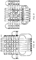
- Figure 6A illustrates in side view a short section of a wood laminate slat (generally illustrated as element 402) which may comprise the basic building element of the interlocking slat lattice according to the present invention.
- the slat comprises two major faces which are bent in the following manner.
- a central imaginary plane 404 (perpendicular to the plane of the drawing figure) defines the location of alternating contact surfaces 414, 416, 414, 416 . . . . These alternating contact surfaces 414 and 416 are faces of corresponding parallel segments 408 and 412, which are located on opposite sides of the central plane 404. Consecutive parallel segments 408 and 412 are joined by connecting segments 406 and 410 which pass through the central plane 404 at an angle so as to join consecutive parallel segments.
- Figure 6B illustrates the manner in which slats overlap and interlock so as to form the lattice structure which provides the aesthetic and structural advantages of furniture according to the present invention.
- Figure 6B illustrates the slat 402 of Figure 6A in conjunction with perpendicular slats 420, 422, 424 and 426 (shown in cross section, as they are perpendicular to the plane of the drawing figure). The perpendicular slats contact the original slat 402 at contact surfaces 414 and 416.
- slats 420, 422, 424 and 426 are substantially the same as slat 402, and because the perpendicular slats intersect the original in the central plane 400, two surface planes 430 and 432 are defined by the outer surfaces of the interlocking slats.
- slats having substantially identical thickness allow a smooth surface to be presented to the user of the furniture. That is, when considering a surface of the furniture which is large compared to the slats, a substantially smooth surface is experienced. This implies that, when a person sits in the chair, he or she does not experience an irregular surface which may cause discomfort.
- angles of interconnecting segments 406 and 410 on the main slat prevent adjacent parallel slats 420 through 426 from shifting laterally on slat 402.
- the intersecting slats are preferably affixed to one another using adhesive at the contact surfaces so as to enhance the structural strength provided by their interlocking configuration.
- the slats shown in Figure 6B may be fabricated thin in width W (such as 2"(5.08cm)) with narrow spaces S between adjacent parallel slats (such as 0.75" (1.9cm)), so that an individual sitting on or feeling the furniture is presented with a substantially smooth and continuous planar surface 430 or 432.
- Individual slat thickness T of 3/16" (0.476cm) allows a total lattice thickness 2T of only 3/8" (0.95cm), rendering the furniture light in weight and appearance.
- the slats may be of dimensions other than the specific dimensions provided here.
- Typical slat widths W may range from 1/2" (1.27cm) to 5" (12.7cm), with corresponding separation S of 3/8" (0.95cm) to 1" (2.54cm), and thickness T of 1/8" (0.318cm) to 3/8" (0.95cm).
- slat thickness, width and separation should be chosen in light of considerations of strength, aesthetics and interlocking characteristics. For example, a widening of the separation may lighten the chair, but strength and the interlocking nature of the slats may be compromised as well as some of the ergonomic comfort. That is, a greater separation of longitudinal slats causes the interconnecting segments of transverse slats to be longer, and thus more oblique in angle. This obliqueness of angle reduces the interlocking strength of the lattice, so that the strength of the structure is more dependent on any adhesive which joins overlapping slats.
- the reduction in strength and interlocking nature may be compensated, for example, by increasing the increasing the thickness of the slats.
- Increasing the slat thickness increases the strength of the lattice both directly (by providing more load-bearing capability) as well as indirectly (by causing the interconnecting segments to be of a less oblique angle, thus enhancing the interlocking nature).
- Extra slat thickness may create a too flat and unyielding feel to the surface of the chair. Retaining a certain amount of flexibility to the overall surface of the chair is essential for physical comfort.
- the slats may be fabricated of varying thickness, width, separation, and angle of intersection.
- different portions of any given piece of furniture may comprise the interlocking lattice provided by the invention, either alone or in combination with other structural and aesthetic elements of the furniture.
- the process of placing the unlaminated sheets on the forms and assembly of accompanying pressing means may be performed in an order other than that described specifically above.
Landscapes
- Engineering & Computer Science (AREA)
- Life Sciences & Earth Sciences (AREA)
- Manufacturing & Machinery (AREA)
- Wood Science & Technology (AREA)
- Forests & Forestry (AREA)
- Mechanical Engineering (AREA)
- Laminated Bodies (AREA)
Claims (9)
- Stuhl mit einem Sitzteil, einem Rückenteil und Stützbeinen, wobei der Stuhl eine Vielzahl von ersten Latten umfasst, die sich in einer ersten Richtung erstrecken, und nebeneinander angeordnet sind, wobei jede der ersten Latten sich abwechselnde erste Vertiefungen einschließt, und die angeordnet sind, um ein Teil des Stuhlsitzteils zu definieren, und eine Vielzahl von zweiten Latten, die sich in eine zweite Richtung erstrecken, und nebeneinander angeordnet sind, wobei jede der zweiten Latten sich abwechselnde zweite Vertiefungen einschließt, und in einem verflochtenen Verhältnis mit den ersten Vertiefungen angeordnet sind, um das Gleichgewicht des Stuhlsitzteils zu definieren, wobei die ersten und zweiten Teile das Stuhlsitzteil, das Stuhlrückenteil und die Stützbeine definieren.
- Stuhl nach Anspruch 1, in dem die ersten und zweiten Latten vorzugsweise aus Holz hergestellt sind.
- Stuhl nach Anspruch 1 oder 2, in dem wenigstens die ersten und/oder die zweiten Latten aus laminierten Schichten hergestellt sind.
- Stuhl nach einem der Ansprüche 1 bis 3, in dem Befestigungsmittel vorgesehen sind, um die ersten und zweiten Latten an den Kreuzpunkten zu befestigen.
- Stuhl nach einem der Ansprüche 1 bis 4, in dem die ersten und zweiten Richtungen rechtwinklig zueinander sind, und die ersten und zweiten Vertiefungen angepaßt sind, um sich an den Kreuzpunkten in dem Stuhlsitz zu ergänzen, um wesentlich flache obere und untere Oberflächen in dem Stuhlsitz zu definieren.
- Stuhl nach Anspruch 5, der ein Grundplattenmittel einschließt, um das Stuhlsitzteil zu unterstützen, wobei das Grundplattenmittel auch von den ersten und zweiten Latten definiert ist.
- Stuhl nach einem der Ansprüche 1 bis 6, in dem das Oberflächengebiet durch ein Gitter von Latten definiert ist, die durch ineinandergreifende Streifen definiert sind, wobei jeder Streifen viele Schichten aus laminiertem Holz einschließt, wobei die Streifen zwei Flächen und eine Reihe aufeinanderfolgender Abschnitte haben, wobei die aufeinanderfolgenden Abschnitte sich abwechselnde Kontaktoberflächenabschnitte und verbindende Abschnitte umfasst, und Kontaktoberflächenabschnitte neben einer imaginären mittleren Ebene angeordnet sind, wobei aufeinanderfolgende Kontaktoberflächenabschnitte auf gegenüberliegenden Seiten der imaginären Ebene liegen, so daß aufeinanderfolgende Kontaktoberflächen auf gegenüberliegenden Flächen der Streifen sind, und die verbindenden Abschnitte die imaginäre mittlere Ebene durchqueren, um aufeinanderfolgende Kontaktoberflächenabschnitte zu verbinden, in der das Gitter umfasst, daß sich die Streifen überlappen und sich an entsprechenden Kontaktoberflächen berühren, und in das Gitter durch den Winkel der verbindenden Abschnitte einschlossen werden.
- Stuhl nach Anspruch 7, in dem die überlappenden Streifen des Gitters an den Kontaktoberflächen, an denen sie sich berühren, aneinander befestigt sind, und die Streifen sich im wesentlichen rechtwinklig überlappen.
- Stuhl nach Anspruch 8, in dem die Streifen aus laminiertem Holz im wesentlichen eine gemeinsame Dicke haben, so daß das Gitter global zwei Gitteroberflächenebenen umfasst, die im wesentlichen glatt sind, und einen gleichen Abstand von der imaginären mittleren Ebene haben.
Applications Claiming Priority (2)
| Application Number | Priority Date | Filing Date | Title |
|---|---|---|---|
| US07/588,115 US5154486A (en) | 1990-09-24 | 1990-09-24 | Furniture comprising laminated slats and methods of manufacturing such furniture |
| US588115 | 2000-05-31 |
Publications (2)
| Publication Number | Publication Date |
|---|---|
| EP0478224A1 EP0478224A1 (de) | 1992-04-01 |
| EP0478224B1 true EP0478224B1 (de) | 1996-02-21 |
Family
ID=24352544
Family Applications (1)
| Application Number | Title | Priority Date | Filing Date |
|---|---|---|---|
| EP91308545A Expired - Lifetime EP0478224B1 (de) | 1990-09-24 | 1991-09-19 | Möbel mit laminierten Latten |
Country Status (6)
| Country | Link |
|---|---|
| US (2) | US5154486A (de) |
| EP (1) | EP0478224B1 (de) |
| JP (1) | JP3176965B2 (de) |
| AT (1) | ATE134299T1 (de) |
| CA (1) | CA2051524C (de) |
| DE (1) | DE69117238T2 (de) |
Families Citing this family (37)
| Publication number | Priority date | Publication date | Assignee | Title |
|---|---|---|---|---|
| USD341263S (en) | 1991-11-25 | 1993-11-16 | Westinghouse Electric Corp. | Club chair |
| USD344191S (en) | 1991-11-25 | 1994-02-15 | Westinghouse Electric Corp. | Dining chair |
| US5338570A (en) * | 1993-02-18 | 1994-08-16 | Westinghouse Electric Corp. | Method for finishing wood slatted articles of furniture |
| DE4410383C2 (de) * | 1994-03-25 | 1996-07-25 | Desanta | Stuhl |
| US5735573A (en) * | 1996-08-20 | 1998-04-07 | Vredevoogd; Jon D. | Chair with power seat |
| CN100478509C (zh) * | 2001-12-05 | 2009-04-15 | 休闲生活世界股份有限公司 | 用合成的织造材料制造家具的方法 |
| US6705070B2 (en) | 2001-12-05 | 2004-03-16 | Sun Isle Casual Furniture, Llc | Method of making furniture with synthetic woven material |
| US20040031534A1 (en) * | 2001-12-05 | 2004-02-19 | Sun Isle Casual Furniture, Llc | Floor covering from synthetic twisted yarns |
| US6935383B2 (en) | 2001-12-05 | 2005-08-30 | Sun Isle Casual Furniture, Llc | Combination weave using twisted and nontwisted yarn |
| US6725640B2 (en) | 2001-12-05 | 2004-04-27 | Sun Isle Casual Furniture, Llc | Method of making furniture with synthetic woven material |
| US6625970B2 (en) | 2001-12-05 | 2003-09-30 | Sun Isle Casual Furniture, Llc | Method of making twisted elongated yarn |
| US7472961B2 (en) | 2003-11-18 | 2009-01-06 | Casual Living Worldwide, Inc. | Woven articles from synthetic yarns |
| US7472536B2 (en) * | 2003-11-18 | 2009-01-06 | Casual Living Worldwide, Inc. | Coreless synthetic yarns and woven articles therefrom |
| US7472535B2 (en) * | 2003-11-18 | 2009-01-06 | Casual Living Worldwide, Inc. | Coreless synthetic yarns and woven articles therefrom |
| USD533370S1 (en) * | 2004-08-09 | 2006-12-12 | Rehmert Rory S | Recliner |
| DE102005032850A1 (de) * | 2005-07-14 | 2007-01-18 | Maurice Berg | Herstellungsverfahren für ein Stuhlelement sowie Stuhlelement |
| US7806473B1 (en) * | 2005-11-21 | 2010-10-05 | Faiks Frederick S | Stackable chair and framework therefor |
| ITMO20050336A1 (it) * | 2005-12-16 | 2007-06-17 | Tecnoform Spa | Metodo per la produzione di componenti curvi da arredo, particolarmente ante per mobili |
| RU2318934C1 (ru) * | 2006-07-05 | 2008-03-10 | Виталий Васильевич Мережкин | Способ изготовления плетеных конструкций |
| CN101632525B (zh) * | 2009-04-17 | 2012-07-04 | 国立台湾工艺研究所 | 竹片椅及其制造方法 |
| TWI405549B (zh) * | 2009-04-17 | 2013-08-21 | Bamboo chair and its manufacturing method | |
| CN102396910B (zh) * | 2010-09-08 | 2013-09-18 | 胡森川 | 条形嵌接椅 |
| US8256845B2 (en) * | 2010-09-28 | 2012-09-04 | Wen-Tsan Wang | Bamboo chair |
| AR078643A1 (es) * | 2010-10-15 | 2011-11-23 | Gonzalez Negrin Martin Daniel | Silla con respaldo desplazable hacia posiciones de uso con distinta inclinacion. |
| US8414080B2 (en) * | 2010-10-25 | 2013-04-09 | Wen-Tsan Wang | Flexible bamboo chair |
| CN105593058A (zh) * | 2013-10-07 | 2016-05-18 | 约翰逊控制技术公司 | 座椅结构 |
| US10765211B2 (en) | 2018-11-26 | 2020-09-08 | Jbl International, Inc | Furniture component and method of forming such a furniture component |
| FR3112527B1 (fr) * | 2020-07-17 | 2022-12-23 | Stelia Aerospace | Ossature pour siège d’aéronef constituée de pièces planes découpées et assemblées et son procédé de fabrication |
| CN112894673B (zh) * | 2021-01-15 | 2022-04-22 | 南京林业大学 | 一种户外休闲座椅安装拼装辅助工具 |
| USD1102167S1 (en) * | 2024-01-30 | 2025-11-18 | Shahram Dardashti | Chair |
| USD1095068S1 (en) * | 2024-07-12 | 2025-09-30 | New Classic Home Furnishings, Inc. | Chair |
| USD1091169S1 (en) * | 2024-08-17 | 2025-09-02 | Minghua Guo | Dining chair |
| USD1085744S1 (en) * | 2025-01-20 | 2025-07-29 | Qing Lin | Dining chair |
| USD1085743S1 (en) * | 2025-01-23 | 2025-07-29 | Qing Lin | Dining chair |
| USD1079306S1 (en) * | 2025-03-17 | 2025-06-17 | Yangyang Cai | Dining chair |
| USD1080230S1 (en) * | 2025-03-21 | 2025-06-24 | Guangyu LUO | Bench |
| USD1080229S1 (en) * | 2025-03-21 | 2025-06-24 | Guangyu LUO | Bench |
Family Cites Families (27)
| Publication number | Priority date | Publication date | Assignee | Title |
|---|---|---|---|---|
| FR853697A (de) * | 1940-03-26 | |||
| DE278237C (de) * | ||||
| US723006A (en) * | 1902-12-24 | 1903-03-17 | Henry B Morris | Chair. |
| FR361122A (fr) * | 1905-12-28 | 1906-05-18 | Jean Marie Bernard Clarens | Système de sommiers métalliques élastiques |
| FR14271E (fr) * | 1909-05-27 | 1911-10-24 | Georges Vigie | Perfectionnements aux sommiers métalliques |
| US1385387A (en) * | 1920-07-01 | 1921-07-26 | Morandi Giuseppe | Wooden article and process of making the same |
| US1548026A (en) * | 1923-05-28 | 1925-08-04 | Benjamin H Dietz | Forming apparatus for wood veneer strips or bands |
| NL52091A (de) * | 1929-03-27 | 1900-01-01 | Elmendorf Armin | |
| US2373738A (en) * | 1941-11-01 | 1945-04-17 | Harry N Atwood | Sheet material |
| US2386821A (en) * | 1942-10-27 | 1945-10-16 | Tardiff George Emil | Method of making laminated structures |
| CH278237A (de) * | 1949-11-10 | 1951-10-15 | Werner Horst Fa | Möbel, insbesondere zum Ruhen. |
| US2640517A (en) * | 1950-11-13 | 1953-06-02 | Mello Ruben De | Apparatus for manufacture of corrugated plywood |
| US2640527A (en) * | 1951-05-04 | 1953-06-02 | Norman M Kreizelman | Knockdown bent wood furniture |
| US2692007A (en) * | 1952-02-11 | 1954-10-19 | William N Christian | Fisherman's chair |
| FR1398052A (fr) * | 1964-03-25 | 1965-05-07 | Treillis, réseau et produits similaires en matière plastique | |
| US3225431A (en) * | 1964-07-22 | 1965-12-28 | Woodard Mfg Company | Method of manufacturing woven metal articles of furniture |
| US3792899A (en) * | 1972-12-29 | 1974-02-19 | Wicker Works | Woven and braided furniture |
| US4210182A (en) * | 1976-06-08 | 1980-07-01 | Danko Peter J | Method of making a chair |
| USD249836S (en) | 1977-02-16 | 1978-10-10 | Henry Olko | Chair |
| US4145084A (en) * | 1977-07-25 | 1979-03-20 | Capper Joan M | Miniature wicker furniture and method of assembling same |
| US4188983A (en) * | 1978-07-12 | 1980-02-19 | W. T. Rogers Co. | Woven construction system |
| USD266545S (en) | 1979-01-19 | 1982-10-19 | Pacific Furniture Manufacturing Co. | Bench |
| USD267135S (en) | 1980-06-25 | 1982-12-07 | Lewittes Furniture Enterprises, Inc. | Chair |
| US4495019A (en) * | 1982-05-21 | 1985-01-22 | Richard Ogg | Plywood bending |
| US4586751A (en) * | 1984-11-13 | 1986-05-06 | The Mcguire Company Of San Francisco | Method of assembling rattan furniture |
| USD296628S (en) | 1986-12-16 | 1988-07-12 | Iron Mountain Forge | Seat |
| US5040487A (en) * | 1990-05-03 | 1991-08-20 | Bollyky Associates, Inc. | Method for controlling Zebra Mussel (Dreissena polymorpha) |
-
1990
- 1990-09-24 US US07/588,115 patent/US5154486A/en not_active Expired - Lifetime
-
1991
- 1991-09-17 CA CA002051524A patent/CA2051524C/en not_active Expired - Lifetime
- 1991-09-19 DE DE69117238T patent/DE69117238T2/de not_active Expired - Fee Related
- 1991-09-19 AT AT91308545T patent/ATE134299T1/de not_active IP Right Cessation
- 1991-09-19 EP EP91308545A patent/EP0478224B1/de not_active Expired - Lifetime
- 1991-09-20 JP JP27029891A patent/JP3176965B2/ja not_active Expired - Lifetime
-
1992
- 1992-03-27 US US07/858,705 patent/US5284380A/en not_active Expired - Lifetime
Also Published As
| Publication number | Publication date |
|---|---|
| JPH0686721A (ja) | 1994-03-29 |
| ATE134299T1 (de) | 1996-03-15 |
| CA2051524A1 (en) | 1992-03-25 |
| US5284380A (en) | 1994-02-08 |
| CA2051524C (en) | 2000-01-25 |
| JP3176965B2 (ja) | 2001-06-18 |
| EP0478224A1 (de) | 1992-04-01 |
| US5154486A (en) | 1992-10-13 |
| DE69117238D1 (de) | 1996-03-28 |
| DE69117238T2 (de) | 1996-10-31 |
Similar Documents
| Publication | Publication Date | Title |
|---|---|---|
| US5154486A (en) | Furniture comprising laminated slats and methods of manufacturing such furniture | |
| US3756656A (en) | Chair | |
| EP2241221B1 (de) | Bambusstuhl und Verfahren zur Herstellung des Bambusstuhls | |
| US8388064B2 (en) | Stackable chair with flexible back | |
| US5605378A (en) | Take-apart chair | |
| US20070018495A1 (en) | An article of rattan furniture having a seat support cushion | |
| US5431479A (en) | Tandem chair assembly | |
| US4114949A (en) | Seating arrangement | |
| CZ179295A3 (en) | Combined chair | |
| US5695244A (en) | Rocking chair with wood-laminated seat and continuous runners | |
| US6413349B1 (en) | Method of manufacturing furniture structures using laminated sheet materials | |
| KR200463114Y1 (ko) | 발포 폴리에틸렌 시트를 이용한 쿠션 쇼파 | |
| US2503933A (en) | Plywood furniture frame | |
| NL193928C (nl) | Steunmiddel uit schuimmateriaal, zoals een matras of een zittingdeel. | |
| US4955667A (en) | Seating in the form of a chair or similar piece of furniture | |
| CN201546415U (zh) | 一种实木复合地板 | |
| CN201870147U (zh) | 改进的竹制悬臂椅结构 | |
| US8590975B2 (en) | Furniture construction | |
| US4917439A (en) | Chair incorporating improved chairback support structure | |
| JP2020029659A (ja) | 板材及び建築資材 | |
| KR200428298Y1 (ko) | 자리 | |
| CN204260270U (zh) | 一种框架椅 | |
| KR100804172B1 (ko) | 자리 | |
| CN204260269U (zh) | 一种框架椅 | |
| KR200467754Y1 (ko) | 발포 폴리에틸렌 시트를 이용한 쿠션 쇼파 |
Legal Events
| Date | Code | Title | Description |
|---|---|---|---|
| PUAI | Public reference made under article 153(3) epc to a published international application that has entered the european phase |
Free format text: ORIGINAL CODE: 0009012 |
|
| AK | Designated contracting states |
Kind code of ref document: A1 Designated state(s): AT CH DE ES FR GB IT LI NL SE |
|
| 17P | Request for examination filed |
Effective date: 19920905 |
|
| 17Q | First examination report despatched |
Effective date: 19941118 |
|
| GRAA | (expected) grant |
Free format text: ORIGINAL CODE: 0009210 |
|
| AK | Designated contracting states |
Kind code of ref document: B1 Designated state(s): AT CH DE ES FR GB IT LI NL SE |
|
| PG25 | Lapsed in a contracting state [announced via postgrant information from national office to epo] |
Ref country code: ES Free format text: THE PATENT HAS BEEN ANNULLED BY A DECISION OF A NATIONAL AUTHORITY Effective date: 19960221 Ref country code: IT Free format text: LAPSE BECAUSE OF FAILURE TO SUBMIT A TRANSLATION OF THE DESCRIPTION OR TO PAY THE FEE WITHIN THE PRE;WARNING: LAPSES OF ITALIAN PATENTS WITH EFFECTIVE DATE BEFORE 2007 MAY HAVE OCCURRED AT ANY TIME BEFORE 2007. THE CORRECT EFFECTIVE DATE MAY BE DIFFERENT FROM THE ONE RECORDED.SCRIBED TIME-LIMIT Effective date: 19960221 |
|
| REF | Corresponds to: |
Ref document number: 134299 Country of ref document: AT Date of ref document: 19960315 Kind code of ref document: T |
|
| ET | Fr: translation filed | ||
| REF | Corresponds to: |
Ref document number: 69117238 Country of ref document: DE Date of ref document: 19960328 |
|
| REG | Reference to a national code |
Ref country code: CH Ref legal event code: NV Representative=s name: A. BRAUN, BRAUN, HERITIER, ESCHMANN AG PATENTANWAE |
|
| PGFP | Annual fee paid to national office [announced via postgrant information from national office to epo] |
Ref country code: CH Payment date: 19960905 Year of fee payment: 6 |
|
| PG25 | Lapsed in a contracting state [announced via postgrant information from national office to epo] |
Ref country code: AT Effective date: 19960919 |
|
| PG25 | Lapsed in a contracting state [announced via postgrant information from national office to epo] |
Ref country code: SE Effective date: 19960920 |
|
| PLBE | No opposition filed within time limit |
Free format text: ORIGINAL CODE: 0009261 |
|
| STAA | Information on the status of an ep patent application or granted ep patent |
Free format text: STATUS: NO OPPOSITION FILED WITHIN TIME LIMIT |
|
| REG | Reference to a national code |
Ref country code: GB Ref legal event code: 732E |
|
| 26N | No opposition filed | ||
| PG25 | Lapsed in a contracting state [announced via postgrant information from national office to epo] |
Ref country code: NL Effective date: 19970401 |
|
| REG | Reference to a national code |
Ref country code: FR Ref legal event code: TP |
|
| NLV4 | Nl: lapsed or anulled due to non-payment of the annual fee |
Effective date: 19970401 |
|
| EUG | Se: european patent has lapsed |
Ref document number: 91308545.2 |
|
| PG25 | Lapsed in a contracting state [announced via postgrant information from national office to epo] |
Ref country code: LI Free format text: LAPSE BECAUSE OF NON-PAYMENT OF DUE FEES Effective date: 19970930 Ref country code: CH Free format text: LAPSE BECAUSE OF NON-PAYMENT OF DUE FEES Effective date: 19970930 |
|
| REG | Reference to a national code |
Ref country code: CH Ref legal event code: PL |
|
| PGFP | Annual fee paid to national office [announced via postgrant information from national office to epo] |
Ref country code: FR Payment date: 19980820 Year of fee payment: 8 |
|
| PGFP | Annual fee paid to national office [announced via postgrant information from national office to epo] |
Ref country code: DE Payment date: 19980826 Year of fee payment: 8 Ref country code: GB Payment date: 19980826 Year of fee payment: 8 |
|
| PG25 | Lapsed in a contracting state [announced via postgrant information from national office to epo] |
Ref country code: GB Free format text: LAPSE BECAUSE OF NON-PAYMENT OF DUE FEES Effective date: 19990919 |
|
| GBPC | Gb: european patent ceased through non-payment of renewal fee |
Effective date: 19990919 |
|
| PG25 | Lapsed in a contracting state [announced via postgrant information from national office to epo] |
Ref country code: FR Free format text: LAPSE BECAUSE OF NON-PAYMENT OF DUE FEES Effective date: 20000531 |
|
| PG25 | Lapsed in a contracting state [announced via postgrant information from national office to epo] |
Ref country code: DE Free format text: LAPSE BECAUSE OF NON-PAYMENT OF DUE FEES Effective date: 20000701 |
|
| REG | Reference to a national code |
Ref country code: FR Ref legal event code: ST |