EP0478375A2 - Structure pivotable - Google Patents
Structure pivotable Download PDFInfo
- Publication number
- EP0478375A2 EP0478375A2 EP91308872A EP91308872A EP0478375A2 EP 0478375 A2 EP0478375 A2 EP 0478375A2 EP 91308872 A EP91308872 A EP 91308872A EP 91308872 A EP91308872 A EP 91308872A EP 0478375 A2 EP0478375 A2 EP 0478375A2
- Authority
- EP
- European Patent Office
- Prior art keywords
- curved surface
- pivot member
- socket member
- socket
- pivot
- Prior art date
- Legal status (The legal status is an assumption and is not a legal conclusion. Google has not performed a legal analysis and makes no representation as to the accuracy of the status listed.)
- Granted
Links
Images



Classifications
-
- F—MECHANICAL ENGINEERING; LIGHTING; HEATING; WEAPONS; BLASTING
- F16—ENGINEERING ELEMENTS AND UNITS; GENERAL MEASURES FOR PRODUCING AND MAINTAINING EFFECTIVE FUNCTIONING OF MACHINES OR INSTALLATIONS; THERMAL INSULATION IN GENERAL
- F16M—FRAMES, CASINGS OR BEDS OF ENGINES, MACHINES OR APPARATUS, NOT SPECIFIC TO ENGINES, MACHINES OR APPARATUS PROVIDED FOR ELSEWHERE; STANDS; SUPPORTS
- F16M11/00—Stands or trestles as supports for apparatus or articles placed thereon ; Stands for scientific apparatus such as gravitational force meters
- F16M11/02—Heads
- F16M11/04—Means for attachment of apparatus; Means allowing adjustment of the apparatus relatively to the stand
- F16M11/06—Means for attachment of apparatus; Means allowing adjustment of the apparatus relatively to the stand allowing pivoting
- F16M11/10—Means for attachment of apparatus; Means allowing adjustment of the apparatus relatively to the stand allowing pivoting around a horizontal axis
-
- Y—GENERAL TAGGING OF NEW TECHNOLOGICAL DEVELOPMENTS; GENERAL TAGGING OF CROSS-SECTIONAL TECHNOLOGIES SPANNING OVER SEVERAL SECTIONS OF THE IPC; TECHNICAL SUBJECTS COVERED BY FORMER USPC CROSS-REFERENCE ART COLLECTIONS [XRACs] AND DIGESTS
- Y10—TECHNICAL SUBJECTS COVERED BY FORMER USPC
- Y10S—TECHNICAL SUBJECTS COVERED BY FORMER USPC CROSS-REFERENCE ART COLLECTIONS [XRACs] AND DIGESTS
- Y10S248/00—Supports
- Y10S248/917—Video display screen support
- Y10S248/919—Adjustably orientable video screen support
- Y10S248/922—Angular
- Y10S248/923—Tilting
-
- Y—GENERAL TAGGING OF NEW TECHNOLOGICAL DEVELOPMENTS; GENERAL TAGGING OF CROSS-SECTIONAL TECHNOLOGIES SPANNING OVER SEVERAL SECTIONS OF THE IPC; TECHNICAL SUBJECTS COVERED BY FORMER USPC CROSS-REFERENCE ART COLLECTIONS [XRACs] AND DIGESTS
- Y10—TECHNICAL SUBJECTS COVERED BY FORMER USPC
- Y10T—TECHNICAL SUBJECTS COVERED BY FORMER US CLASSIFICATION
- Y10T403/00—Joints and connections
- Y10T403/32—Articulated members
- Y10T403/32254—Lockable at fixed position
- Y10T403/32262—At selected angle
Definitions
- This invention relates to apparatus for rotatably supporting a structure.
- the supported structure is an optical bar code scanning device.
- the supported structure could be a display unit for an electronic cash register or a CRT monitor screen unit for a video display.
- apparatus for rotatably supporting a structure characterized by a support member having a socket member, wherein said structure has mounted thereon a pivot member formed of a resilient material, which is adapted to be inserted into said socket member, said pivot member being deformed when inserted within said socket member and being adapted to slidably engage said socket member, whereby the frictional force exerted between said pivot member and said socket member enables said structure to be rotatably moved to and maintained in a selected position.
- Apparatus according to the invention has the advantage that a simple, low-cost apparatus is provided which can position and maintain the supported structure in a wide range of orientations.
- the supported structure is an optical bar code scanner
- such scanner can be positioned vertically, or horizontally on either side of the vertical, whereby merchandise items can be scanned by passing the items either under or over or by a side of the scanner, as is convenient, such that a highly versatile; adjustable scanner is provided.
- FIG. 1 there is shown a perspective view of the optical scanner generally indicated by the numeral 18 which includes a box-like housing member 20 having a front cover portion 22 in which is located a transparent aperture 24.
- the housing member 20 is rotatably mounted on a support member generally indicated by the numeral 26 which includes a base member 27 and a clam shell socket member 28 mounted in the base member 27 and to which the housing member 20 is rotatably secured for frictional movement about the socket member in a manner to be described hereinafter.
- the scanning apparatus 30 includes an box-like inner housing member 32 with the front portion of such housing member being open which is positioned adjacent the aperture 24 (Fig. 1) of the housing member 20.
- the inner housing member 32 includes a cylindrical portion 34 within which is mounted a visible laser diode (not shown) for projecting a laser light beam to a molded routing mirror 36 which deflects the laser light beam along a light path for engagement with one of eight plano reflecting mirrors 38 of a rotating spinner member 40.
- the reflecting mirrors or facets 38 are set at various angles with respect to the axis of rotation of the spinner member 40. Four of these facets will reflect the received laser light beam in a direction which strikes a large pattern mirror 42 while the remaining four facets will reflect the laser light beam at a small pattern forming mirror 44 located adjacent the large pattern forming mirror 42 for reflecting the light beams in the form of a scanning pattern through the aperture 24 (Fig. 1).
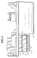
- FIG. 3 there is shown a side view of the housing member 20 (Fig. 1) with the sidewall portion of the socket member 28 removed showing details of the pivot member allowing the housing member 20 (Fig. 1) to be rotated about the socket member 28.
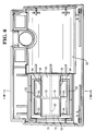
- the socket member 28 is comprised of a pair of clam shell members 46 (Fig. 8), each having one end enclosed by a side wall portion 48 (Figs. 1 and 8), and which are joined together to form a hollow cylinder 50.
- the clam shell members include a depending leg portion 49 having a base portion 51 which when inserted into the base member 27 will form the socket member 28.
- Removably inserted into the open end of the cylinder 50 is a pivot member 52 secured to the cylindrically shaped lower housing portion 54 of the housing member 20.
- the pivot member 52 which is composed of a polycarbonate plastic material is molded in a generally W-shaped configuration (Figs. 3 and 8) and includes an elongated body portion 55 (Fig. 6) having a pair of depending flexible arm portions 56.
- Each of the arm portions 56 includes an upturned curved end portion 58 which when inserted into the cylinder 50 will be compressed by the inner wall surface 53 of the cylinder 50.
- the engagement of the wall surface 53 by the flexible end portions 58 provides a frictional drag on the cylinder 50 when the housing member 20 is rotated, enabling the housing member to be located in any scanning position between the vertical position (Fig. 1) and two horizontal positions (Figs. 4A and 4B).
- the pivot member 52 is molded as one end of the lower housing portion 54 of the housing member 20 in which the other end of the housing portion includes a recessed portion 60 (Fig. 6) within which is positioned the spinner member 61 of the scanning apparatus 30 (Fig. 2) when the housing portion 54 is mounted to the scanning apparatus and the housing member 20.
- the pivot member 52, the housing portion 54 and the housing members 20 and 32 are molded of a polycarbonate material such as POLCARBONATE /ABS BAYBLEND which is commercially available from the Mobay Corp. of Pittsburgh, Pa., 15205-9741.
- each of the flexible end portions 58 includes a plurality of rib portions 64 connecting the end portions 58 to the arm portions 56 which transfer the flexing movement of the end portions 58 when mounted within the cylinder 50 to the arm portions.
- a pair of rib sections 70 are mounted between the rib member 62, the body portion 55 and the arm portions 56 as shown in Figs. 3 and 4-6 inclusive to transfer the stresses to the rib member 62.
- the pivot member 52 is molded integral with the end of the lower housing portion 54 through the rib member 62 and the body portion 55 while the arm portions 56 (Fig. 5) are free to be deflected when the pivot member is inserted into the cylindrical portion 50 of the support member 26.
- the outer surface 72 of the flexible end portions 58 represents the arc of a circle whose diameter is slightly larger than the inside diameter of the cylindrical portion 50 of the support member.
- the end portions 58 and the arm portions 56 of the pivot member 52 will deflect, applying a frictional force on the inside surface 53 of the cylindrical portion 50, allowing the housing member 20 to be rotated between a vertical (Fig. 1) and a horizontal position (Figs. 4A and 4B), enabling the optical scanner to be used in a variety of checkout configurations.
- the present invention allows the pivot member and the scanner to be easily removed from the support member 26 when it is necessary to repair the scanner. This arrangement also allows a single scanner to be used with more than one support member, enabling a greater use of the scanner within a place of business.
Landscapes
- Engineering & Computer Science (AREA)
- General Engineering & Computer Science (AREA)
- Mechanical Engineering (AREA)
- Pivots And Pivotal Connections (AREA)
- Facsimile Scanning Arrangements (AREA)
Applications Claiming Priority (2)
| Application Number | Priority Date | Filing Date | Title |
|---|---|---|---|
| US07/590,577 US5108062A (en) | 1990-09-28 | 1990-09-28 | Pivot apparatus |
| US590577 | 1990-09-28 |
Publications (3)
| Publication Number | Publication Date |
|---|---|
| EP0478375A2 true EP0478375A2 (fr) | 1992-04-01 |
| EP0478375A3 EP0478375A3 (fr) | 1994-01-26 |
| EP0478375B1 EP0478375B1 (fr) | 1996-12-11 |
Family
ID=24362801
Family Applications (1)
| Application Number | Title | Priority Date | Filing Date |
|---|---|---|---|
| EP91308872A Expired - Lifetime EP0478375B1 (fr) | 1990-09-28 | 1991-09-27 | Structure pivotable |
Country Status (4)
| Country | Link |
|---|---|
| US (1) | US5108062A (fr) |
| EP (1) | EP0478375B1 (fr) |
| JP (1) | JPH04360292A (fr) |
| DE (1) | DE69123534T2 (fr) |
Cited By (3)
| Publication number | Priority date | Publication date | Assignee | Title |
|---|---|---|---|---|
| EP0742405A1 (fr) * | 1995-05-08 | 1996-11-13 | International Business Machines Corporation | Dispositif d'inclinaison variable |
| EP2146131A3 (fr) * | 2008-07-14 | 2012-03-28 | LG Electronics Inc. | Dispositif d'affichage |
| GB2583803A (en) * | 2019-01-11 | 2020-11-11 | Zebra Tech Corp | Industrial digital barcode scanner |
Families Citing this family (25)
| Publication number | Priority date | Publication date | Assignee | Title |
|---|---|---|---|---|
| US5192857A (en) * | 1990-09-28 | 1993-03-09 | Ncr Corporation | Compact optical scanner rotatable between horizontal and vertical positions |
| US5593119A (en) * | 1995-01-12 | 1997-01-14 | At&T Global Information Solutions Company | Apparatus and method for mounting a terminal |
| EP0989351B1 (fr) * | 1995-03-22 | 2004-02-25 | Canon Kabushiki Kaisha | Structure de support et dispositif de visualisation équipé de la structure de support |
| US5697125A (en) | 1995-11-27 | 1997-12-16 | Reell Precision Manufacturing Corporation | Clip friction hinge |
| US5765794A (en) * | 1996-09-12 | 1998-06-16 | Chen; Ping | Angle adjusting device for an instrument panel |
| US5730406A (en) * | 1996-09-17 | 1998-03-24 | Chen; Ping | Adjusting device for a display panel |
| KR100212314B1 (ko) * | 1996-11-06 | 1999-08-02 | 윤종용 | 액정 디스플레이 장치의 스탠드구조 |
| KR100212313B1 (ko) | 1996-11-06 | 1999-08-02 | 윤종용 | 와이어 꼬임이 없는 액정디스플레이장치 |
| KR100234420B1 (ko) * | 1996-11-06 | 1999-12-15 | 윤종용 | 액정디스플레이장치 |
| DE29710833U1 (de) * | 1996-11-16 | 1997-08-28 | ADI Corporation, Tai Ping Shiang, Taichung | LCD-Tragekonstruktion |
| KR100242840B1 (ko) * | 1997-05-27 | 2000-02-01 | 윤종용 | 액정디스플레이장치 |
| US5938163A (en) * | 1997-10-20 | 1999-08-17 | Eastman Kodak Company | Articulating touchscreen interface |
| US6302612B1 (en) * | 1998-03-16 | 2001-10-16 | International Business Machines Corporation | Pivotally extensible display device |
| US6561333B2 (en) | 2000-07-14 | 2003-05-13 | Reell Precision Manufacturing Corporation | Spring clutch utilizing torque slip clips |
| KR100609872B1 (ko) * | 2000-11-17 | 2006-08-09 | 삼성전자주식회사 | 컴퓨터장치 |
| KR100395092B1 (ko) * | 2001-07-27 | 2003-08-21 | 삼성전기주식회사 | 무선랜 어댑터 |
| WO2007052410A1 (fr) * | 2005-11-04 | 2007-05-10 | Nec Personal Products, Ltd. | Dispositif électronique et organe de bâti |
| EP1887273A3 (fr) * | 2006-08-10 | 2009-06-10 | Samsung Electronics Co., Ltd. | Appareil de support pour dispositifs de visualisation et dispositif de visualisation le comprenant |
| US9070007B2 (en) * | 2013-01-11 | 2015-06-30 | Datalogic ADC, Inc. | Adjustable data reader with pivot mount |
| EP2976538B1 (fr) | 2013-03-21 | 2018-10-10 | Reell Precision Manufacturing Corporation | Charnière à pince multi-axe à bille et à douille |
| WO2015038640A1 (fr) | 2013-09-10 | 2015-03-19 | Reell Precision Manufacturing Corporation | Système de retenue d'élément de couple |
| US10605347B2 (en) | 2015-09-16 | 2020-03-31 | Reell Precision Manufacturing Corporation | Ring clip assembly |
| US12141651B2 (en) * | 2019-06-03 | 2024-11-12 | Zebra Technologies Corporation | Digital barcode reader |
| USD916060S1 (en) * | 2019-10-16 | 2021-04-13 | David Arthur Brown | Microphone |
| USD1000418S1 (en) * | 2023-06-14 | 2023-10-03 | Bing Qiu | Combined phone stand and speaker |
Family Cites Families (13)
| Publication number | Priority date | Publication date | Assignee | Title |
|---|---|---|---|---|
| US3179361A (en) * | 1963-05-23 | 1965-04-20 | Standard Pyroxoloid Corp | Mirror and easel therefor |
| US3531823A (en) * | 1967-12-06 | 1970-10-06 | Cornelius Co | Hinge |
| FR2036598A5 (fr) * | 1969-03-26 | 1970-12-24 | Parry Paul | |
| CA861762A (en) * | 1969-01-10 | 1971-01-26 | Dominion Auto Accessories Limited | Hinge joint assemblies |
| US4589713A (en) * | 1984-04-09 | 1986-05-20 | Raytheon Company | Video display support joint |
| US4666068A (en) * | 1984-10-25 | 1987-05-19 | Sunbeam Plastics Corporation | Two piece dispensing closure |
| US4624434A (en) * | 1984-12-19 | 1986-11-25 | Burroughs Corporation | Stable tiltable display terminal |
| US4645153A (en) * | 1985-05-23 | 1987-02-24 | Ncr Corporation | Tilt and swivel support |
| JPS6217282A (ja) * | 1985-07-15 | 1987-01-26 | 株式会社 大井製作所 | トラツクにおける荷台のゲ−トヒンジ装置 |
| US4731903A (en) * | 1986-10-27 | 1988-03-22 | White Consolidated Industries, Inc. | Self-latching hinge |
| US4696412A (en) * | 1987-03-09 | 1987-09-29 | Igloo Corporation | Hinge construction for container covers |
| US4790504A (en) * | 1987-12-21 | 1988-12-13 | Ncr Corporation | Display support mechanism |
| US4986507A (en) * | 1989-09-08 | 1991-01-22 | Arthur Chiang | Free positioning tilt unit |
-
1990
- 1990-09-28 US US07/590,577 patent/US5108062A/en not_active Expired - Lifetime
-
1991
- 1991-09-26 JP JP3273586A patent/JPH04360292A/ja active Pending
- 1991-09-27 EP EP91308872A patent/EP0478375B1/fr not_active Expired - Lifetime
- 1991-09-27 DE DE69123534T patent/DE69123534T2/de not_active Expired - Fee Related
Cited By (5)
| Publication number | Priority date | Publication date | Assignee | Title |
|---|---|---|---|---|
| EP0742405A1 (fr) * | 1995-05-08 | 1996-11-13 | International Business Machines Corporation | Dispositif d'inclinaison variable |
| US5771152A (en) * | 1995-05-08 | 1998-06-23 | International Business Machines Corporation | Computer system with a tilt adjustment mechanism |
| EP2146131A3 (fr) * | 2008-07-14 | 2012-03-28 | LG Electronics Inc. | Dispositif d'affichage |
| US8256724B2 (en) | 2008-07-14 | 2012-09-04 | Lg Electronics Inc. | Display device |
| GB2583803A (en) * | 2019-01-11 | 2020-11-11 | Zebra Tech Corp | Industrial digital barcode scanner |
Also Published As
| Publication number | Publication date |
|---|---|
| DE69123534D1 (de) | 1997-01-23 |
| EP0478375A3 (fr) | 1994-01-26 |
| DE69123534T2 (de) | 1997-09-04 |
| US5108062A (en) | 1992-04-28 |
| EP0478375B1 (fr) | 1996-12-11 |
| JPH04360292A (ja) | 1992-12-14 |
Similar Documents
| Publication | Publication Date | Title |
|---|---|---|
| EP0478375A2 (fr) | Structure pivotable | |
| US5214270A (en) | Modular handheld or fixed scanner | |
| US5155346A (en) | Device for converting hand-held scanner to hands-free scanner | |
| TW480452B (en) | Optical path design for scanning assembly in compact bar code readers | |
| JP2763957B2 (ja) | 一体のスキャナエンジンを備えたポータブルレーザスキャナ | |
| EP0453183B1 (fr) | Appareil atténuateur de rayon laser | |
| EP0490601A1 (fr) | Appareil d'exploration optique pour lire des symboles codés | |
| US7199933B2 (en) | Image projection screen with reduced speckle noise | |
| US5192857A (en) | Compact optical scanner rotatable between horizontal and vertical positions | |
| JPH04291475A (ja) | 小型の高性能走査装置 | |
| US6502753B2 (en) | Compact dual aperture scanner | |
| US6427916B1 (en) | Polygonal mirror unit, optical scanning apparatus and bar code reader | |
| US5191199A (en) | Bar code scanner support member | |
| US6211990B1 (en) | Optical scanning device | |
| JPH05210751A (ja) | 軸固定パターン式走査方法および装置 | |
| US7521279B2 (en) | Image projection at different image planes | |
| JP3873723B2 (ja) | レーザー墨出し装置 | |
| JPH06318289A (ja) | 表示装置 | |
| JPH0283684A (ja) | 定置型スキヤナ | |
| JPH03116391A (ja) | デテクタ・アセンブリ | |
| US6922296B2 (en) | Optical path adjusting device | |
| KR200402066Y1 (ko) | 전면과 배면을 동시에 볼 수 있는 거울의 설치구조 | |
| JPH0720998Y2 (ja) | 画像読取装置 | |
| KR200402085Y1 (ko) | 전면과 배면을 동시에 볼 수 있는 거울 | |
| JP3626559B2 (ja) | 光学素子用傾角調整装置 |
Legal Events
| Date | Code | Title | Description |
|---|---|---|---|
| PUAI | Public reference made under article 153(3) epc to a published international application that has entered the european phase |
Free format text: ORIGINAL CODE: 0009012 |
|
| AK | Designated contracting states |
Kind code of ref document: A2 Designated state(s): DE FR GB |
|
| PUAL | Search report despatched |
Free format text: ORIGINAL CODE: 0009013 |
|
| AK | Designated contracting states |
Kind code of ref document: A3 Designated state(s): DE FR GB |
|
| 17P | Request for examination filed |
Effective date: 19940709 |
|
| RAP1 | Party data changed (applicant data changed or rights of an application transferred) |
Owner name: AT&T GLOBAL INFORMATION SOLUTIONS INTERNATIONAL IN |
|
| 17Q | First examination report despatched |
Effective date: 19950119 |
|
| GRAG | Despatch of communication of intention to grant |
Free format text: ORIGINAL CODE: EPIDOS AGRA |
|
| GRAH | Despatch of communication of intention to grant a patent |
Free format text: ORIGINAL CODE: EPIDOS IGRA |
|
| RAP1 | Party data changed (applicant data changed or rights of an application transferred) |
Owner name: NCR INTERNATIONAL, INC. |
|
| GRAH | Despatch of communication of intention to grant a patent |
Free format text: ORIGINAL CODE: EPIDOS IGRA |
|
| GRAA | (expected) grant |
Free format text: ORIGINAL CODE: 0009210 |
|
| AK | Designated contracting states |
Kind code of ref document: B1 Designated state(s): DE FR GB |
|
| REF | Corresponds to: |
Ref document number: 69123534 Country of ref document: DE Date of ref document: 19970123 |
|
| ET | Fr: translation filed | ||
| PLBE | No opposition filed within time limit |
Free format text: ORIGINAL CODE: 0009261 |
|
| STAA | Information on the status of an ep patent application or granted ep patent |
Free format text: STATUS: NO OPPOSITION FILED WITHIN TIME LIMIT |
|
| 26N | No opposition filed | ||
| REG | Reference to a national code |
Ref country code: GB Ref legal event code: IF02 |
|
| REG | Reference to a national code |
Ref country code: GB Ref legal event code: 746 Effective date: 20020619 |
|
| PGFP | Annual fee paid to national office [announced via postgrant information from national office to epo] |
Ref country code: GB Payment date: 20040628 Year of fee payment: 14 |
|
| PGFP | Annual fee paid to national office [announced via postgrant information from national office to epo] |
Ref country code: FR Payment date: 20040723 Year of fee payment: 14 |
|
| PGFP | Annual fee paid to national office [announced via postgrant information from national office to epo] |
Ref country code: DE Payment date: 20040827 Year of fee payment: 14 |
|
| PG25 | Lapsed in a contracting state [announced via postgrant information from national office to epo] |
Ref country code: GB Free format text: LAPSE BECAUSE OF NON-PAYMENT OF DUE FEES Effective date: 20050927 |
|
| PG25 | Lapsed in a contracting state [announced via postgrant information from national office to epo] |
Ref country code: DE Free format text: LAPSE BECAUSE OF NON-PAYMENT OF DUE FEES Effective date: 20060401 |
|
| GBPC | Gb: european patent ceased through non-payment of renewal fee |
Effective date: 20050927 |
|
| PG25 | Lapsed in a contracting state [announced via postgrant information from national office to epo] |
Ref country code: FR Free format text: LAPSE BECAUSE OF NON-PAYMENT OF DUE FEES Effective date: 20060531 |
|
| REG | Reference to a national code |
Ref country code: FR Ref legal event code: ST Effective date: 20060531 |