EP0478420B1 - Systeme zur elektromagnetischen Bestimmung von Position und Lage eines beweglichen Körpers - Google Patents
Systeme zur elektromagnetischen Bestimmung von Position und Lage eines beweglichen Körpers Download PDFInfo
- Publication number
- EP0478420B1 EP0478420B1 EP91402487A EP91402487A EP0478420B1 EP 0478420 B1 EP0478420 B1 EP 0478420B1 EP 91402487 A EP91402487 A EP 91402487A EP 91402487 A EP91402487 A EP 91402487A EP 0478420 B1 EP0478420 B1 EP 0478420B1
- Authority
- EP
- European Patent Office
- Prior art keywords
- sensor
- axes
- cos
- transmission
- sequentially
- Prior art date
- Legal status (The legal status is an assumption and is not a legal conclusion. Google has not performed a legal analysis and makes no representation as to the accuracy of the status listed.)
- Expired - Lifetime
Links
Images

Classifications
-
- F—MECHANICAL ENGINEERING; LIGHTING; HEATING; WEAPONS; BLASTING
- F41—WEAPONS
- F41G—WEAPON SIGHTS; AIMING
- F41G3/00—Aiming or laying means
- F41G3/22—Aiming or laying means for vehicle-borne armament, e.g. on aircraft
- F41G3/225—Helmet sighting systems
-
- G—PHYSICS
- G01—MEASURING; TESTING
- G01S—RADIO DIRECTION-FINDING; RADIO NAVIGATION; DETERMINING DISTANCE OR VELOCITY BY USE OF RADIO WAVES; LOCATING OR PRESENCE-DETECTING BY USE OF THE REFLECTION OR RERADIATION OF RADIO WAVES; ANALOGOUS ARRANGEMENTS USING OTHER WAVES
- G01S3/00—Direction-finders for determining the direction from which infrasonic, sonic, ultrasonic or electromagnetic waves, or particle emission, not having a directional significance, are being received
- G01S3/02—Direction-finders for determining the direction from which infrasonic, sonic, ultrasonic or electromagnetic waves, or particle emission, not having a directional significance, are being received using radio waves
- G01S3/023—Monitoring or calibrating
-
- G—PHYSICS
- G01—MEASURING; TESTING
- G01S—RADIO DIRECTION-FINDING; RADIO NAVIGATION; DETERMINING DISTANCE OR VELOCITY BY USE OF RADIO WAVES; LOCATING OR PRESENCE-DETECTING BY USE OF THE REFLECTION OR RERADIATION OF RADIO WAVES; ANALOGOUS ARRANGEMENTS USING OTHER WAVES
- G01S3/00—Direction-finders for determining the direction from which infrasonic, sonic, ultrasonic or electromagnetic waves, or particle emission, not having a directional significance, are being received
- G01S3/02—Direction-finders for determining the direction from which infrasonic, sonic, ultrasonic or electromagnetic waves, or particle emission, not having a directional significance, are being received using radio waves
- G01S3/14—Systems for determining direction or deviation from predetermined direction
- G01S3/143—Systems for determining direction or deviation from predetermined direction by vectorial combination of signals derived from differently oriented antennae
Definitions
- the principle of electromagnetic position detection is well known for determining the position and orientation of a mobile, solid, in a reference frame.
- One of the applications of this principle is the determination of the direction of sight of a helmet sight which an infantryman, a driver or a pilot of a tank or aircraft has placed on his head, to control a weapon there, a missile or a piloting camera, for example.
- This detection principle uses a transmitter, or radiator, of magnetic field, linked to the reference frame, or reference frame, in which the measurements are carried out, a receiver, or sensor, of magnetic field, fixed to the mobile, the position and orientation must be determined, and electronic processing circuits including analog amplifiers, a computing processor and processing algorithms.
- the radiator must satisfy the conditions of the dipole theory, in which the coordinate system for the mathematical description of the radiation is a sphere centered on the dipole and the Green function of free space depends only on the radial coordinate.
- the magnetic field sensor must be as punctual as possible.
- the transmitter radiates, sequentially or by multiplexing, a field along two or three orthogonal axes and the sensor sequentially detects the components of this field along three or two orthogonal axes, the emission and reception generally taking place along three axes.
- the sensor thus provides, by emission axis, three measurements, ie a total of nine which are organized in a 3 ⁇ 3 matrix, from which the processing algorithms provide the position and the orientation of the sensor relative to the radiator.
- the determination of the position and the orientation of the sensor involves the determination of six variables - the three Cartesian coordinates, the deposit, the site and the roll - and that at least six measurements are therefore necessary. If the transmission is carried out only along two axes, the reception must therefore be carried out along three axes, and vice versa.
- the magnetic field at a given point is represented by a vector H.
- the axes of sensitivity of the sensor are represented by a vector C.
- the results of the measurements carried out by the sensor can be arranged in the form of matrix M corresponding to the scalar product C.
- H H being the matrix of the field and C T the matrix transposed from the matrix C of the axes of sensitivity of the sensor.
- the sensor in the repository, can undergo either a translation or a rotation. Let us consider this one, expressed by a rotation matrix R.
- the matrix of the axes of sensitivity of the sensor becomes RC and that of the measurements M R. If the three axes of the sensor are orthonormal, Therefore H depending on the position of the sensor and M R on its position and orientation.
- the processing algorithms are based on cartographic surveys. To obtain this preliminary mapping, field measurements are carried out by the sensor at multiple points in space to which we therefore associate disturbed measurement matrices. Let M ⁇ be one of these. If the sensor undergoes rotation R, the measurement matrix should become The matrix product MR M R is therefore invariant in rotation and representative of the point considered.
- the mapping aims to determine the correspondence function f between M ⁇ and M c T M ⁇ .
- a matrix M R corresponds to the product M R T M R.
- M R T M R M C T M c
- M c the position of the sensor.
- the radiator and the sensor of this system are each made up of a group of three identical coils controlled by current and arranged respectively along three orthogonal axes.
- the dimensions of the coils are as small as possible.
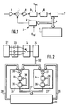
- the processing chain of the signals delivered by the sensor comprises one channel per axis and on each channel, in reference to FIG. 1, an amplifier 1 and an analog servo loop 2, between a mixer 3 and a bus 4 of the calculation processor 5, to avoid the phenomena of crosstalk coupling and improve the precision and, in the mixer 3 , subtract from the signal delivered a signal Vref in phase with it, of the same frequency and almost of the same amplitude.
- the servo is controlled by software of the calculation processor 5 continuously updated to take account of the previous measurement.
- the reference signal supplied to the mixer 3 is fixed by a digital-analog converter DAC 6 controlled by the processor 5.
- the output signal from the control loop 2 is supplied to the calculation processor 5 after conversion in an analog-digital converter ADC 7.
- the loop 2 comprises an amplifier 8, a demodulator 9 and an integrator 10.
- the demodulator 9 provides synchronous and coherent demodulation and rectifies the signal from the mixer 3 by multiplication by the signal Vref of the same frequency and in phase.
- the integrator 10 integrates the signal from the demodulator 9 over a period of time determined by the processor 5 and the result of the integration is digitized in the CAN converter 7.
- the present invention aims to overcome these drawbacks.
- the present invention relates to a system for electromagnetic determination of the position and orientation of a mobile comprising a magnetic radiator, linked to a reference frame, a magnetic sensor, fixed to the mobile, the radiator sequentially radiating fields as follows.
- orthogonal transmission axes and the sensor sequentially supplying detection signals of the components of the emission fields along orthogonal reception axes, the product of the number of transmission axes and the number of reception axes being at least equal to six, a chain for processing the sensor signals to determine its amplitudes and a calculation processor with a support for processing algorithms
- system characterized in that it comprises a multiplexer connected to the output of the sensor, for sequentially multiplexing the sensor detection signals on a channel, a device for sampling the signal leaving the multiplexer , of amplitude A and of pulsation ⁇ and corresponding to a couple of two axes of emission and reception, means for multiplying the samples of the sampling device respectively by reference signals sin wt and cos wt and means for accumulate the two sums
- the system of the invention derives its advantage from the uniqueness of the signal processing chain of the sensor, from its simplicity, allowing entirely digital processing, and from its insensitivity to phase timing.
- the sampling device comprises a fast analog-digital converter, called “flash”, and the samples of the converter are processed in at least one fast MAC multiplier-accumulator.
- the system comprises two rapid multiplier-accumulators receiving respectively the two reference signals sin wt and cos wt.
- the signal processing chain of the sensor 21, receiving the magnetic fields emitted by a transmitter comprises, in series between the sensor and the calculation processor 22, a preamplification block 23, with a preamplifier on each of the reception channels, here three in number, a sequential multiplexer 24, a sampling block 25, here consisting of a fast analog-digital converter of the "flash" type, and two MAC fast accumulator multipliers 26, 27 in parallel.
- the transmitter, or radiator is connected to the processor 22 by a power amplification block.
- the two MACs receive respectively on two multipliers 30, 31 two reference signals sin wt and cos ⁇ t, the two multipliers 30, 31 also receiving from the sampling block 25, by a bus 32, the signal A cos (wt + ⁇ ) corresponding to one of the pairs of two transmission and reception axes, ⁇ representing the phase shift of the received signal with respect to the reference signals, each of the signals associated respectively with all the pairs of transmission and reception axes being captured by sequential multiplexing on one channel of the multiplexer 24.
- Each fast accumulator multiplier 26 (27) comprises a digital summator 33 (34), receiving the signal from the multiplier 30 (31), and a memory register 35 (36), 35 (36), connected by a bus 37 to the processor 22 and by a bus 38 (39) to the adder 33 (34).
- the samples of the signal A cos (wt + ⁇ ) are multiplied by sin ⁇ t, cos ⁇ t in the multiplier 30.31.
- the product of each multiplication is added digitally in the summator 33,34 to the result previously accumulated in the register 35,36, the new result overwriting the previous one in the register 35,36.
- These operations of multiplication, summation and accumulation are repeated over a duration here equal to several periods 2 ⁇ ⁇ before the accumulated result is transferred to the processor 22 for exploitation and calculation of A and determination of the position and the orientation sought by determination of the matrices M R , M C and R ..
- the output of its multiplier provides: Due to the accumulation of the products of multiplication over a long period, here equal to several periods the terms dependent on wt cancel each other and the continuous term - sin ⁇ is thus extracted.
- the output of its multiplier provides: Due to the accumulation of the products of multiplication over a long period, here equal to several periods the terms depending on ⁇ t cancel each other and we extract the continuous term A 2 cos processeur Processor 22 squares the two results add them up and extract the square root of the sum to determine and therefore A.
- the amplitude A of the signal A cos ( ⁇ t + ⁇ ) leaving the sampling block 25 was calculated.
- the result of the calculation is tainted with an error due in particular to parasitic couplings (couplings between axes, capacitive or inductive couplings with the sensor output wires), in short, to sensor faults.
- the phase angle of the useful measurement is equal to Let ⁇ therefore be the phase shift, with respect to the reference axis of the abscissae, of the amplitude measurement axis
- the vector OA is the result of the component OA ', along the useful measurement axis phase shifted by ⁇ u , whose amplitude, useful, is to be determined, and of a component OA "perpendicular - + 90 ° or - 90 ° depending on whether we consider capacitive or inductive couplings - to the component OA .
Landscapes
- Engineering & Computer Science (AREA)
- Physics & Mathematics (AREA)
- General Physics & Mathematics (AREA)
- Radar, Positioning & Navigation (AREA)
- Remote Sensing (AREA)
- Aviation & Aerospace Engineering (AREA)
- General Engineering & Computer Science (AREA)
- Measurement Of Length, Angles, Or The Like Using Electric Or Magnetic Means (AREA)
Claims (5)
Applications Claiming Priority (2)
| Application Number | Priority Date | Filing Date | Title |
|---|---|---|---|
| FR9011850 | 1990-09-26 | ||
| FR9011850A FR2667145B1 (fr) | 1990-09-26 | 1990-09-26 | Systeme de determination electromagnetique de la position et de l'orientation d'un mobile. |
Publications (2)
| Publication Number | Publication Date |
|---|---|
| EP0478420A1 EP0478420A1 (de) | 1992-04-01 |
| EP0478420B1 true EP0478420B1 (de) | 1995-04-05 |
Family
ID=9400655
Family Applications (1)
| Application Number | Title | Priority Date | Filing Date |
|---|---|---|---|
| EP91402487A Expired - Lifetime EP0478420B1 (de) | 1990-09-26 | 1991-09-18 | Systeme zur elektromagnetischen Bestimmung von Position und Lage eines beweglichen Körpers |
Country Status (5)
| Country | Link |
|---|---|
| US (1) | US5168222A (de) |
| EP (1) | EP0478420B1 (de) |
| JP (1) | JP3165474B2 (de) |
| DE (1) | DE69108657T2 (de) |
| FR (1) | FR2667145B1 (de) |
Families Citing this family (23)
| Publication number | Priority date | Publication date | Assignee | Title |
|---|---|---|---|---|
| JPH05288818A (ja) * | 1992-04-06 | 1993-11-05 | Seiko Instr Inc | 三次元積分磁束計 |
| BE1007126A3 (nl) * | 1992-06-24 | 1995-04-04 | Andre Albert Madelein Heerwegh | Werkwijze en inrichting voor het lezen van driedimensionele informatie. |
| US5418460A (en) * | 1992-07-21 | 1995-05-23 | Innovatum, Inc. | Compact triaxial AC magnetic field analyzer/dosimeter using swept bandpass filters |
| DE4224225C2 (de) * | 1992-07-22 | 1996-03-14 | Walter Dr Mehnert | Schaltungsanordnung für einen induktiven Stellungsgeber |
| US5453686A (en) * | 1993-04-08 | 1995-09-26 | Polhemus Incorporated | Pulsed-DC position and orientation measurement system |
| US5558091A (en) | 1993-10-06 | 1996-09-24 | Biosense, Inc. | Magnetic determination of position and orientation |
| DE4407785A1 (de) * | 1994-03-09 | 1995-09-14 | Philips Patentverwaltung | Anordnung zur Bestimmung der räumlichen Position eines gegenüber einem Bezugselement verschiebbaren Abtastelements |
| US6690963B2 (en) | 1995-01-24 | 2004-02-10 | Biosense, Inc. | System for determining the location and orientation of an invasive medical instrument |
| US5640170A (en) * | 1995-06-05 | 1997-06-17 | Polhemus Incorporated | Position and orientation measuring system having anti-distortion source configuration |
| US6054951A (en) * | 1995-08-28 | 2000-04-25 | Sypniewski; Jozef | Multi-dimensional tracking sensor |
| IL126284A (en) | 1998-09-17 | 2002-12-01 | Netmor Ltd | System and method for three dimensional positioning and tracking |
| US6487516B1 (en) | 1998-10-29 | 2002-11-26 | Netmor Ltd. | System for three dimensional positioning and tracking with dynamic range extension |
| US6172499B1 (en) * | 1999-10-29 | 2001-01-09 | Ascension Technology Corporation | Eddy current error-reduced AC magnetic position measurement system |
| US6528989B1 (en) * | 2000-03-21 | 2003-03-04 | Skysense, Ltd. | AC magnetic tracker for operation close to metallic objects |
| US6484118B1 (en) * | 2000-07-20 | 2002-11-19 | Biosense, Inc. | Electromagnetic position single axis system |
| US7809421B1 (en) * | 2000-07-20 | 2010-10-05 | Biosense, Inc. | Medical system calibration with static metal compensation |
| DE10036090B4 (de) * | 2000-07-25 | 2004-01-29 | Lust Antriebstechnik Gmbh | Verfahren zur Unterdrückung systematischer Fehler von inkrementellen Lagegebern |
| US6691074B1 (en) | 2001-02-08 | 2004-02-10 | Netmore Ltd. | System for three dimensional positioning and tracking |
| WO2003050990A2 (en) * | 2001-12-07 | 2003-06-19 | Stoneridge Control Devices, Inc. | Phase angle determining circuit |
| US7432836B2 (en) * | 2006-08-01 | 2008-10-07 | Hamilton Sundstrand Corporation | Multiplexed signal conditioner |
| FR2972316B1 (fr) * | 2011-03-03 | 2013-03-22 | Thales Sa | Emetteur electromagnetique emettant simultanement selon trois axes orthogonaux pour detection de position et d'orientation d'objets |
| US9391630B2 (en) | 2014-06-13 | 2016-07-12 | Hamilton Sundstrand Corporation | Multiplexed signal sampler and conditioner |
| CA3149712C (en) | 2021-03-04 | 2026-03-31 | Northern Digital, Inc. | Magnetic position measurement system with interference reduction |
Family Cites Families (8)
| Publication number | Priority date | Publication date | Assignee | Title |
|---|---|---|---|---|
| US4054881A (en) * | 1976-04-26 | 1977-10-18 | The Austin Company | Remote object position locater |
| FR2458838A1 (fr) * | 1979-06-06 | 1981-01-02 | Thomson Csf | Dispositif de mesure de l'orientation relative de deux corps et systeme de reperage de direction correspondant |
| US4688037A (en) * | 1980-08-18 | 1987-08-18 | Mcdonnell Douglas Corporation | Electromagnetic communications and switching system |
| US4394831A (en) * | 1981-02-12 | 1983-07-26 | Honeywell Inc. | Helmet metal mass compensation for helmet-mounted sighting system |
| JPS58151513A (ja) * | 1982-03-05 | 1983-09-08 | Alps Electric Co Ltd | 移動体の現在位置更新表示装置 |
| JPS59672A (ja) * | 1982-06-27 | 1984-01-05 | Tsutomu Jinno | 測距センサ |
| US4635207A (en) * | 1984-11-19 | 1987-01-06 | Ici Americas Inc. | Field measuring system |
| US4829250A (en) * | 1988-02-10 | 1989-05-09 | Honeywell, Inc. | Magnetic direction finding device with improved accuracy |
-
1990
- 1990-09-26 FR FR9011850A patent/FR2667145B1/fr not_active Expired - Fee Related
-
1991
- 1991-09-18 DE DE69108657T patent/DE69108657T2/de not_active Expired - Fee Related
- 1991-09-18 EP EP91402487A patent/EP0478420B1/de not_active Expired - Lifetime
- 1991-09-24 US US07/764,894 patent/US5168222A/en not_active Expired - Fee Related
- 1991-09-26 JP JP24749091A patent/JP3165474B2/ja not_active Expired - Fee Related
Also Published As
| Publication number | Publication date |
|---|---|
| DE69108657D1 (de) | 1995-05-11 |
| DE69108657T2 (de) | 1996-04-11 |
| FR2667145B1 (fr) | 1993-08-13 |
| JP3165474B2 (ja) | 2001-05-14 |
| US5168222A (en) | 1992-12-01 |
| FR2667145A1 (fr) | 1992-03-27 |
| EP0478420A1 (de) | 1992-04-01 |
| JPH0727503A (ja) | 1995-01-27 |
Similar Documents
| Publication | Publication Date | Title |
|---|---|---|
| EP0478420B1 (de) | Systeme zur elektromagnetischen Bestimmung von Position und Lage eines beweglichen Körpers | |
| EP0021906B1 (de) | Vorrichtung zur Messung der relativen Orientierung zweier Körper und entsprechendes System zur Richtungsbestimmung | |
| CA2009423C (en) | Aperture synthesized radiometer using digital beamforming techniques | |
| EP0589554B1 (de) | Flugzeugvermessungsverfahren und -gerät | |
| Ruf et al. | Interferometric synthetic aperture microwave radiometry for the remote sensing of the Earth | |
| EP0215695A1 (de) | Verfahren und Vorrichtung zum Lokalisieren eines Objekts und Bestimmen seiner Orientierung im Raum | |
| CA2073300C (en) | Method of correcting range migration in image generation in synthetic aperture radar | |
| FR2787201A1 (fr) | Methode et dispositif d'acquisition synchronisee de signaux sismiques | |
| CA2131633A1 (fr) | Procede et dispositif de localisation de bruiteurs par une antenne constituee de bouees acoustiques passives | |
| FR2741955A1 (fr) | Procede et dispositif de mesure d'attitude de satellite | |
| FR2749398A1 (fr) | Procede et dispositif de geodesie et/ou d'imagerie par traitement de signaux satellitaires | |
| WO2009138441A1 (fr) | Systeme de mesure de champ magnetique comprenant un capteur triaxial de mesure de champ magnetique mobile conjointement avec un element porteur perturbant les mesures et procede associe | |
| EP0147305B1 (de) | Anordnung zur Unterscheidung von Radarechos | |
| EP1671140B1 (de) | Vorrichtung zur messung eines magnetfeldes | |
| EP2156209B1 (de) | Verfahren und einrichtung zur bestimmung des peilwinkels in einem funknavigationssystem des tacan-typs | |
| US6441376B1 (en) | Method and system for two-dimensional interferometric radiometry | |
| FR2664044A1 (fr) | Procede et dispositif de determination d'une orientation liee a un systeme mobile, notamment de la ligne de visee dans un viseur de casque. | |
| US12620977B2 (en) | Device and method for processing a digital signal | |
| CA2100822A1 (fr) | Systeme de controle de canalisations, notamment de canalisations en acier nu ou enrobe | |
| US20240426707A1 (en) | Device and method for processing a digital signal | |
| EP0267086A1 (de) | Raumfahrzeug mit Ausrichtanordnung einer Antenne zur Erde | |
| FR2727764A1 (fr) | Restitution de pointage en elevation, notamment pour radar a synthese d'ouverture | |
| EP3710869B1 (de) | Verfahren zur kompensation eines magnetischen lokalisators, lokalisator und computerprogramm | |
| CN119788166B (zh) | 卫星载荷信号绝对时延的确定方法、装置、存储介质 | |
| WO2003044987A1 (fr) | Recepteur de faisceaux incidents resultant de trajets multiples |
Legal Events
| Date | Code | Title | Description |
|---|---|---|---|
| PUAI | Public reference made under article 153(3) epc to a published international application that has entered the european phase |
Free format text: ORIGINAL CODE: 0009012 |
|
| AK | Designated contracting states |
Kind code of ref document: A1 Designated state(s): DE FR GB IT NL |
|
| 17P | Request for examination filed |
Effective date: 19920928 |
|
| 17Q | First examination report despatched |
Effective date: 19940805 |
|
| GRAA | (expected) grant |
Free format text: ORIGINAL CODE: 0009210 |
|
| AK | Designated contracting states |
Kind code of ref document: B1 Designated state(s): DE FR GB IT NL |
|
| REF | Corresponds to: |
Ref document number: 69108657 Country of ref document: DE Date of ref document: 19950511 |
|
| ITF | It: translation for a ep patent filed | ||
| GBT | Gb: translation of ep patent filed (gb section 77(6)(a)/1977) |
Effective date: 19950605 |
|
| PLBE | No opposition filed within time limit |
Free format text: ORIGINAL CODE: 0009261 |
|
| STAA | Information on the status of an ep patent application or granted ep patent |
Free format text: STATUS: NO OPPOSITION FILED WITHIN TIME LIMIT |
|
| 26N | No opposition filed | ||
| PGFP | Annual fee paid to national office [announced via postgrant information from national office to epo] |
Ref country code: NL Payment date: 19990816 Year of fee payment: 9 |
|
| PG25 | Lapsed in a contracting state [announced via postgrant information from national office to epo] |
Ref country code: NL Free format text: LAPSE BECAUSE OF NON-PAYMENT OF DUE FEES Effective date: 20010401 |
|
| NLV4 | Nl: lapsed or anulled due to non-payment of the annual fee |
Effective date: 20010401 |
|
| PGFP | Annual fee paid to national office [announced via postgrant information from national office to epo] |
Ref country code: DE Payment date: 20010821 Year of fee payment: 11 |
|
| PGFP | Annual fee paid to national office [announced via postgrant information from national office to epo] |
Ref country code: GB Payment date: 20010822 Year of fee payment: 11 |
|
| PGFP | Annual fee paid to national office [announced via postgrant information from national office to epo] |
Ref country code: FR Payment date: 20010925 Year of fee payment: 11 |
|
| REG | Reference to a national code |
Ref country code: GB Ref legal event code: IF02 |
|
| PG25 | Lapsed in a contracting state [announced via postgrant information from national office to epo] |
Ref country code: GB Free format text: LAPSE BECAUSE OF NON-PAYMENT OF DUE FEES Effective date: 20020918 |
|
| PG25 | Lapsed in a contracting state [announced via postgrant information from national office to epo] |
Ref country code: DE Free format text: LAPSE BECAUSE OF NON-PAYMENT OF DUE FEES Effective date: 20030401 |
|
| GBPC | Gb: european patent ceased through non-payment of renewal fee |
Effective date: 20020918 |
|
| PG25 | Lapsed in a contracting state [announced via postgrant information from national office to epo] |
Ref country code: FR Free format text: LAPSE BECAUSE OF NON-PAYMENT OF DUE FEES Effective date: 20030603 |
|
| REG | Reference to a national code |
Ref country code: FR Ref legal event code: ST |
|
| PG25 | Lapsed in a contracting state [announced via postgrant information from national office to epo] |
Ref country code: IT Free format text: LAPSE BECAUSE OF NON-PAYMENT OF DUE FEES;WARNING: LAPSES OF ITALIAN PATENTS WITH EFFECTIVE DATE BEFORE 2007 MAY HAVE OCCURRED AT ANY TIME BEFORE 2007. THE CORRECT EFFECTIVE DATE MAY BE DIFFERENT FROM THE ONE RECORDED. Effective date: 20050918 |