EP0478431A1 - Kodierungs-Verfahren und -Schaltung eines digitalen Signals, um Skalarprodukte von Vektoren zu berechnen, und entsprechende diskrete Cosinus-Transformation - Google Patents
Kodierungs-Verfahren und -Schaltung eines digitalen Signals, um Skalarprodukte von Vektoren zu berechnen, und entsprechende diskrete Cosinus-Transformation Download PDFInfo
- Publication number
- EP0478431A1 EP0478431A1 EP91402522A EP91402522A EP0478431A1 EP 0478431 A1 EP0478431 A1 EP 0478431A1 EP 91402522 A EP91402522 A EP 91402522A EP 91402522 A EP91402522 A EP 91402522A EP 0478431 A1 EP0478431 A1 EP 0478431A1
- Authority
- EP
- European Patent Office
- Prior art keywords
- fij
- values
- components
- elementary
- bit
- Prior art date
- Legal status (The legal status is an assumption and is not a legal conclusion. Google has not performed a legal analysis and makes no representation as to the accuracy of the status listed.)
- Ceased
Links
Images


Classifications
-
- G—PHYSICS
- G06—COMPUTING OR CALCULATING; COUNTING
- G06F—ELECTRIC DIGITAL DATA PROCESSING
- G06F17/00—Digital computing or data processing equipment or methods, specially adapted for specific functions
- G06F17/10—Complex mathematical operations
- G06F17/16—Matrix or vector computation, e.g. matrix-matrix or matrix-vector multiplication, matrix factorization
-
- G—PHYSICS
- G06—COMPUTING OR CALCULATING; COUNTING
- G06F—ELECTRIC DIGITAL DATA PROCESSING
- G06F7/00—Methods or arrangements for processing data by operating upon the order or content of the data handled
- G06F7/38—Methods or arrangements for performing computations using exclusively denominational number representation, e.g. using binary, ternary, decimal representation
- G06F7/48—Methods or arrangements for performing computations using exclusively denominational number representation, e.g. using binary, ternary, decimal representation using non-contact-making devices, e.g. tube, solid state device; using unspecified devices
- G06F7/544—Methods or arrangements for performing computations using exclusively denominational number representation, e.g. using binary, ternary, decimal representation using non-contact-making devices, e.g. tube, solid state device; using unspecified devices for evaluating functions by calculation
- G06F7/5443—Sum of products
-
- G—PHYSICS
- G06—COMPUTING OR CALCULATING; COUNTING
- G06T—IMAGE DATA PROCESSING OR GENERATION, IN GENERAL
- G06T9/00—Image coding
- G06T9/007—Transform coding, e.g. discrete cosine transform
Definitions
- the invention relates to a method and a circuit for coding a digital signal for determining the dot product (or internal product) of two vectors.
- the method of coding a digital signal to determine the scalar product of two vectors of the same dimension p of components dedicated and object of the present invention is remarkable in that it consists in expressing the value function of the dot product in the form of partial sums of products fi of binary variables ⁇ xki ⁇ , each partial sum of products fi taking one of the values of the fixed components ak according to the values of said binary variables ⁇ xki ⁇ , according to m possibilities, then to decompose, at bit level, each partial sum of products fi in its elementary partial sums at bit level fij for each bit of rank j, each elementary partial sum fij taking one of the values akj according to the values of said binary variables ⁇ xki ⁇ .
- a calculation of the elementary partial sums at the bit fij level is carried out by evaluation of a plurality of 2 m possibilities by variation of the binary values akj, which makes it possible to calculate each partial sum fi from the elementary partial sums at the level bit fij then of the value function of the dot product.
- the coding circuit of a digital signal to determine the scalar product of two vectors of the same dimension p of components dedicated and variables coded on N bits, object of the present invention, is remarkable in that, the value of the dot product being reduced in the form of partial sums fi of binary variables xki, each partial sum of products fi taking one of the values of the fixed components ak according to the values of the binary variables ⁇ xki ⁇ according to m possibilities, this circuit includes logic coding means allowing, from binary variables, to generate for each bit of row j partial sums fj, a plurality of elementary partial sums at bit fij level by evaluation of a plurality of 2 m possibilities by variation of the binary values akj of the bits of the same rank j of the dedicated components and at least one two-dimensional matrix, said two-dimensional matrix corresponding to each bit of rank j dedicated components ak a value and only one of the partial sums at bit fij level, the set of partial sums at bit fij level defining the partial sum fi corresponding.
- the object coding method and circuit of the present invention find application in all types of digital calculation processor and in particular digital image processing and digital data compression processors by discrete cosine transform TCD.
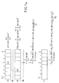
- FIGS. 1a then 1b, 1c A more detailed description of the method of coding a digital signal in order to determine the dot product of two vectors conforming to the object of the present invention will be given in connection with FIGS. 1a then 1b, 1c.
- the coding method which is the subject of the present invention is applied to a digital signal in order to determine the scalar product of two vectors of the same dimension p.
- One of the vectors has dedicated components, denoted ⁇ ak ⁇ , these components being constant for a given application and the other vector has variable components, denoted ⁇ xk ⁇ .
- the components of the two vectors are coded on N bits the bits of the respective components being noted from 0 to N-1 in FIG. 1a, the current bit of each component xk respectively ak being noted i respectively l and the values of these bits being noted respectively xki, aki.
- the value of the dot product of the aforementioned vectors in accordance with the method which is the subject of the invention is expressed by a value function of the dot product noted: and the method which is the subject of the invention consists, as shown in FIG. 1a, in expressing this value function of the scalar product in the form of partial sums of products fi of binary variables xki, these binary variables being of course the corresponding values of each bit of order i on which the above components are coded.
- each component xk in accordance with the process which is the subject of the invention is expressed by the relation: and the value function of the dot product then checks the relation:
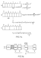
- this then consists in then decomposing at bit level each partial sum of products fi into its elementary partial sums at bit level, denoted fij, j denoting the order of the bits of each partial sum fi coded on N bits.
- each partial sum fi checks the relationship:
- each elementary partial sum fij at the level of each order bit j checks the relation:
- each elementary partial sum fij takes one of the values akj, where akj naturally designates the corresponding binary value of order j of the corresponding component ak, according to the values of the aforementioned binary variables xki.
- the elementary partial sums at bit fij level are then calculated by evaluation of a plurality of 2 m possibilities by variation of the aforementioned binary values akj, which then makes it possible to calculate each sum partial fi from the elementary partial sums at bit fij level then the calculation of the value function of the abovementioned scalar product.
- the method of coding a digital signal to determine the scalar product of two vectors of the same dimension p is in no case limited to a determined dimension of these vectors.
- the number of operations performed as a function of the number of bits on which the components are coded and of the number of these components, and therefore of the size of the abovementioned vectors increases exponentially as a function of these parameters.
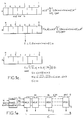
- aj, bj and cj denote corresponding binary values for the bits of rank j of the components a, b or of the parameter c representative of the sum a + b.
- each partial sum fi can take four possible values: a, b, c, 0 taking into account the fact that xi and yi are binary variables. Given that a and b are dedicated components, it is then possible, in accordance with the method which is the subject of the invention, to calculate c to ensure the implementation thereof.
- bit of rank j of each partial sum fi that is to say each elementary partial sum fij, takes the value aj or bj or cj or 0.
- this coding circuit comprising logic circuits making it possible to produce all the combinations of the different binary values xi yi, ie the products xi.yi, xi ⁇ .yi xi. yi ⁇ and xi ⁇ . yi ⁇ .
- Each of the multiplexers receives the corresponding values aj, bj cj and the value 0 and each delivers a bit representative of the corresponding elementary partial sum fij, the partial sum fi then being able to be obtained by concatenation of the bits representative of each elementary partial sum fij.
- the scalar product evaluation function then checks the relationship:
- Ni designates a parameter for checking the absence of value 0,
- Ni 0,
- FIG. 1e The diagram of a circuit allowing the implementation of the method which is the subject of the present invention in its second embodiment in the case of the calculation of a product of two values according to a BME coding is given in FIG. 1e.
- This circuit comprises a modified BOOTH encoder, which from the bits of rank i, i + 1, i + 2 and of corresponding value xi, xi + 1, xi + 2 of the component x delivers the parameters previously described Si, Ni and Ci.
- the modified BOOTH coder in this case is produced using logic circuits of conventional type making it possible to carry out the corresponding logic operations making it possible to define the aforementioned parameters.
- the circuit as represented in FIG. 1e comprises a plurality of multiplexers, which moreover receive the binary variables or bits of order j of the component a, these bits being noted a j with j ranging between 0 and N-1 , allow each to deliver the elementary products fij, the partial product fi then being obtained, as previously in the case of FIG. 1d, by concatenation of the bits delivered by each multiplexer and representative of the elementary partial products fij.
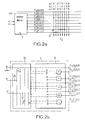
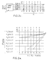
- the circuit comprises a dedicated logic coding circuit, denoted 1, making it possible, from binary variables xki, to generate for each bit of rank i partial sums fj a plurality of elementary partial sums at the bit fij level by evaluation of a plurality of 2 m possibilities by variation of the binary values akj of the bits of the same rank j of the dedicated components ak.
- the coding circuit which is the subject of the present invention also comprises at least one two-dimensional matrix of dimension 2 m , N this two-dimensional matrix, denoted 2, ensuring an interconnection function by making each dedicated bit j correspond to the components dedicated to a value and only one of the partial sums at the bit fij level delivered by the dedicated logic coding circuit 1.
- the set of partial sums at bit fij level defines the corresponding partial sum fi by concatenation of the bits representative of the corresponding elementary partial sums fij, as described previously in the description.
- the circuit for coding a digital signal by dedicated coding is particularly advantageous compared to the embodiment of Figures 1d and 1e previously described since by the introduction of dedicated coding , at the level of the dedicated logic coding circuit 1, this allows the suppression of the multiplexers, these being simply replaced by a two-dimensional matrix of point interconnections, as will be described later in the description.
- each elementary partial sum fij at bit level for each order bit j checks the relationship previously described in the description.
- aj, bj, cj denote the corresponding binary values of order j of the components a, b, c previously defined.
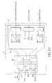
- the dedicated logic coding circuit 1 comprises an input circuit 10 receiving the binary variables xi, yi of rank i of the components x, y.
- This input circuit comprises, as shown in FIG. 2b, two inverters denoted 101, 102 making it possible to generate the complementary values xi ⁇ , yi ⁇ binary variables xi, yi.
- the input circuit 10 delivers the binary variables xi, yi and their complemented values xi ⁇ , yi ⁇ .
- the logic gates used in the plurality of logic gates 11 are essentially constituted either by NOR gates or NAND gates and by an EXCLUSIVE OR gate.
- the dedicated logic coding circuit 1 also includes in this case an input circuit, noted 10, receiving the binary variables xi, xi + 1 and xi + 2 of corresponding rank of the component.
- this input circuit comprising three inverters denoted respectively 101, 102, 103 making it possible to generate the complemented values xi ⁇ , xi + 1 ⁇ and xi + 2 ⁇ binary variables xi, xi + 1, xi + 2.
- the input circuit 10 delivers the aforementioned binary variables and their complemented values.
- the plurality 11 of logic gates delivers the elementary products at the bit fij level, which can be determined for the values of the logical variables aj, bj by the truth table given below in table n ° 3:
- FIG. 2a or 2c A more detailed description of the two-dimensional matrix used in one or other of the embodiments of the coding circuit object of the present invention as shown in FIG. 2a or 2c will be given in connection with FIG. 2d.
- the aforementioned two-dimensional matrix is shown in the nonlimiting case of the first embodiment, the 2 m inputs each receiving a partial sum or elementary product value at the bit level fij.
- the matrix is itself made up of a programmable mesh network between conductors connected to the inputs and conductors connected to the aforementioned outputs.
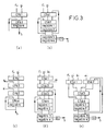
- FIG. 3 at points a, b, c, d, e there is shown an implementation diagram of a device for calculating a scalar product of two vectors of dimension 2q with q> 1.
- each vector is subdivided into q sub-vectors of dimension 2 and each pair of sub-vectors relating to the dedicated components and to the variable components is then submitted by means of one of the coding circuits.
- object of the present invention as shown above in Figure 2a, 2b or 2c, 2d, to a treatment to generate a corresponding partial sum denoted ei, fi, gi or hi for example.
- Each partial sum previously mentioned is introduced into a summing device as shown in points a to e previously mentioned.
- this comprises successively, in order to ensure the summation of two partial sums fi, gi, a first adder with carry propagation propagation denoted CPA1 then a second adder with carry propagation looped to a register whose output is itself looped to an input of the second CPA 2 adder.
- an adder for two partial sums fij is shown, this adder being constituted by a first retained retained adder, denoted CSA1, receiving the two aforementioned partial sums followed by a second adder with retained CSA2, which is coupled to a first and a second summation register, the second summation register being looped back respectively to the first retained adder CSA1 and to the second retained adder CSA2.
- Two output registers and a serial summator make it possible to deliver the result of the summation of the partial sums fi, gi. It will be noted that the first output summator registers one of the outputs of the second retained summation CSA2, while the second summation register registers the other output of the latter.
- the summers produced include an input circuit formed by three retained-retained adders marked CSA1 CSA2 CSA3 on which the partial sums are entered mentioned above, then, analogously to point b of FIG. 3, a CSA4 retained-retained adder coupled to a first and to a second register of summation then to two output registers 3 and 4.
- the three summers with conserved retention CSA1, CSA2, CSA3 are connected according to a tree structure, while at point d of this same figure they are connected in cascade.
- the summers represented in points a to e of FIG. 3 constitute summers at the word level of the partial sums fi, gi, hi, ei.
- Discrete cosine transform processing TCD has so far been applied to real-time data compression or image coding for example. Due to the growing interest in video signal processing of these types of processing, very fast discrete cosine transform processing integrated circuits are necessary to satisfy the required performance.
- the present application of the coding circuit, object of the present invention consists of an integrated circuit of VLSI type for processing by TCD transform.
- the circuit which is the subject of the present invention makes it possible in particular to achieve much higher speeds although the surface area of the integrated circuit necessary for ensure such treatment is less.
- Each of the first 1000 and second 2000 processing channels is subdivided into a plurality of elementary channels formed by a coding circuit according to the present invention.
- the output of a network 2 forming a two-dimensional matrix of the coding circuit according to the invention forming each elementary channel is interconnected with a summing device 3, that is to say with one of the summing devices shown previously in FIG. 3.
- a discrete cosine transform of length 8 can be broken down according to the following transformation product:
- this decomposition has a completely general character in the case of a discrete cosine transform of length M which can be calculated by the two previously mentioned products of two matrices M x N and of a vector of length or dimension M .
- each elementary channel 1001, 1002 of the first channel 1000 comprises two summers in parallel receiving the variable components xo, x7; x1, x6 respectively x2, x5; x3, x4 and a circuit with four programmable networks denoted 1,2,2,2,2 this circuit of course corresponding in its structure to the circuit previously described in the description in connection with FIG. 2a.
- each programmed network corresponds to the dedicated components constituted by p / 2 components of the lines of the computation sub-matrices.
- each elementary channel 2001, 2002 of the second channel 2000 comprises two subtractors in parallel receiving the variable components x4, x3; x2, x5 respectively x1, x6; xo, x7 and a circuit with four programmed networks noted again 1,2,2,2,2 each network programmed corresponding to the dedicated components constituted by p / 2 components of the lines of the computation sub-matrices.
- fi and gi represent the partial sums delivered by the networks 2 of the first 1001, 2001 respectively second 1002, 2002 elementary channels of the processing channels 1000 and 2000.
- Each sub-vector product and variable components corresponding to the results yo, y2, y4, y6 respectively y1, y3, y5, y7 is obtained by means of a summator 3 as shown in Figure 3 at point a or b.
- the programmed networks 2 are programmed as a function of the corresponding coefficients which represent the values of the dedicated components.
- the embodiment of the processing circuit by discrete cosine transform TCD as shown in FIG. 4b relates, on the contrary, to processing at two bits per cycle.
- the evaluation function of the scalar product can be written:
- each elementary channel of the first channel 1000 comprises four elementary channels 1001 to 1004 each elementary channel comprising two cascaded summers receiving the variable components xo, x7; x1, x6 respectively x2, x5; x3, x4.
- the aforementioned cascaded summers deliver three bits of successive rank in parallel relating to the corresponding sums xo + x7, x1 + x6, x2 + x5 and x3 + x4.
- each elementary channel is formed by a circuit with four programmed networks 1,2,2,2,2 each programmed network 2 corresponding to the dedicated components constituted by p / 2 components of the lines of computation sub matrices.
- each elementary channel of the second channel 2000 comprises four elementary channels 2001 to 2004 each of the elementary channels comprising two cascade subtractors delivering three bits of successive rank parallels relative to the corresponding differences x4 - x3, x5 - x2, x1 - x6, x7 - xo.
- Each aforementioned elementary channel also comprises a circuit with four programmed networks 1,2,2,2,2 each programmed network corresponding to the dedicated components constituted by p / 2 components of the lines of the computation sub-matrices.
- TCD processing circuits as shown in FIGS. 4a and 4b can, of course, be applied to TCD processing circuits of larger size.
- a particularly interesting case appears to be, in particular, a TCD processing of length 16.
- a configuration similar to that shown in Figure 4a can be used.
- each input corresponds to a scalar product of dimension 8
- a summing circuit with 4 inputs is necessary.
- a total of 16 summers with four inputs and eight dedicated coding circuits are required.
- a number 2M of summers with M / 2 inputs and M dedicated coding circuits are necessary to process 1 bit per cycle.
- the method and dedicated coding circuits according to the invention appear to be particularly well suited to the processing of digital image data, as well as to the compression of digital data.
Landscapes
- Engineering & Computer Science (AREA)
- Physics & Mathematics (AREA)
- General Physics & Mathematics (AREA)
- Theoretical Computer Science (AREA)
- Computational Mathematics (AREA)
- Mathematical Analysis (AREA)
- Mathematical Optimization (AREA)
- Mathematical Physics (AREA)
- Pure & Applied Mathematics (AREA)
- Data Mining & Analysis (AREA)
- General Engineering & Computer Science (AREA)
- Computing Systems (AREA)
- Algebra (AREA)
- Databases & Information Systems (AREA)
- Software Systems (AREA)
- Discrete Mathematics (AREA)
- Multimedia (AREA)
- Compression, Expansion, Code Conversion, And Decoders (AREA)
- Complex Calculations (AREA)
- Image Processing (AREA)
- Compression Of Band Width Or Redundancy In Fax (AREA)
Applications Claiming Priority (2)
| Application Number | Priority Date | Filing Date | Title |
|---|---|---|---|
| FR9011758 | 1990-09-24 | ||
| FR9011758A FR2667176B1 (fr) | 1990-09-24 | 1990-09-24 | Procede et circuit de codage d'un signal numerique pour determiner le produit scalaire de deux vecteurs et traitement tcd correspondant. |
Publications (1)
| Publication Number | Publication Date |
|---|---|
| EP0478431A1 true EP0478431A1 (de) | 1992-04-01 |
Family
ID=9400592
Family Applications (1)
| Application Number | Title | Priority Date | Filing Date |
|---|---|---|---|
| EP91402522A Ceased EP0478431A1 (de) | 1990-09-24 | 1991-09-23 | Kodierungs-Verfahren und -Schaltung eines digitalen Signals, um Skalarprodukte von Vektoren zu berechnen, und entsprechende diskrete Cosinus-Transformation |
Country Status (4)
| Country | Link |
|---|---|
| US (1) | US5218565A (de) |
| EP (1) | EP0478431A1 (de) |
| JP (1) | JPH0715346A (de) |
| FR (1) | FR2667176B1 (de) |
Cited By (1)
| Publication number | Priority date | Publication date | Assignee | Title |
|---|---|---|---|---|
| EP0621543A3 (de) * | 1993-04-19 | 1995-08-09 | Gen Instrument Corp | Rechner für die inverse diskrete Cosinus-Transformation. |
Families Citing this family (12)
| Publication number | Priority date | Publication date | Assignee | Title |
|---|---|---|---|---|
| US5657423A (en) * | 1993-02-22 | 1997-08-12 | Texas Instruments Incorporated | Hardware filter circuit and address circuitry for MPEG encoded data |
| US6052703A (en) * | 1998-05-12 | 2000-04-18 | Oak Technology, Inc. | Method and apparatus for determining discrete cosine transforms using matrix multiplication and modified booth encoding |
| US7586888B2 (en) * | 2005-02-17 | 2009-09-08 | Mobitrum Corporation | Method and system for mesh network embedded devices |
| US7630736B2 (en) * | 2005-10-11 | 2009-12-08 | Mobitrum Corporation | Method and system for spatial data input, manipulation and distribution via an adaptive wireless transceiver |
| US8305936B2 (en) | 2006-07-27 | 2012-11-06 | Mobitrum Corporation | Method and system for dynamic information exchange on a mesh network in a vehicle |
| USRE47894E1 (en) | 2006-07-27 | 2020-03-03 | Iii Holdings 2, Llc | Method and system for dynamic information exchange on location aware mesh network devices |
| US8305935B2 (en) * | 2006-07-27 | 2012-11-06 | Mobitrum Corporation | Method and system for dynamic information exchange on location aware mesh network devices |
| US8427979B1 (en) | 2006-07-27 | 2013-04-23 | Mobitrum Corporation | Method and system for dynamic information exchange on location aware mesh network devices |
| US8411590B2 (en) | 2006-07-27 | 2013-04-02 | Mobitrum Corporation | Mesh network remote control device |
| US7801058B2 (en) * | 2006-07-27 | 2010-09-21 | Mobitrum Corporation | Method and system for dynamic information exchange on mesh network devices |
| US20090189739A1 (en) * | 2008-01-25 | 2009-07-30 | Mobitrum Corporation | Passive voice enabled rfid devices |
| KR102188490B1 (ko) | 2016-08-31 | 2020-12-09 | 마이크론 테크놀로지, 인크. | 강유전체 메모리를 포함하며 강유전체 메모리에 액세스하기 위한 장치 및 방법 |
Citations (2)
| Publication number | Priority date | Publication date | Assignee | Title |
|---|---|---|---|---|
| EP0078101A2 (de) * | 1981-10-27 | 1983-05-04 | Itt Industries, Inc. | Multiplikationseinrichtung zur Bildung einer Produktensumme |
| EP0327445A1 (de) * | 1988-02-02 | 1989-08-09 | ETAT FRANCAIS représenté par le Ministère des Postes, des Télécommunications et de l'Espace | Allgemeiner digitaler Multiplizierer und digitaler Filter mit diesem Multiplizierer |
Family Cites Families (4)
| Publication number | Priority date | Publication date | Assignee | Title |
|---|---|---|---|---|
| GB8326690D0 (en) * | 1983-10-05 | 1983-11-09 | Secr Defence | Digital data processor |
| US4736335A (en) * | 1984-11-13 | 1988-04-05 | Zoran Corporation | Multiplier-accumulator circuit using latched sums and carries |
| US5032865A (en) * | 1987-12-14 | 1991-07-16 | General Dynamics Corporation Air Defense Systems Div. | Calculating the dot product of large dimensional vectors in two's complement representation |
| US4884232A (en) * | 1987-12-14 | 1989-11-28 | General Dynamics Corp., Pomona Div. | Parallel processing circuits for high speed calculation of the dot product of large dimensional vectors |
-
1990
- 1990-09-24 FR FR9011758A patent/FR2667176B1/fr not_active Expired - Fee Related
-
1991
- 1991-09-23 EP EP91402522A patent/EP0478431A1/de not_active Ceased
- 1991-09-24 US US07/765,001 patent/US5218565A/en not_active Expired - Fee Related
- 1991-09-24 JP JP3272117A patent/JPH0715346A/ja not_active Withdrawn
Patent Citations (2)
| Publication number | Priority date | Publication date | Assignee | Title |
|---|---|---|---|---|
| EP0078101A2 (de) * | 1981-10-27 | 1983-05-04 | Itt Industries, Inc. | Multiplikationseinrichtung zur Bildung einer Produktensumme |
| EP0327445A1 (de) * | 1988-02-02 | 1989-08-09 | ETAT FRANCAIS représenté par le Ministère des Postes, des Télécommunications et de l'Espace | Allgemeiner digitaler Multiplizierer und digitaler Filter mit diesem Multiplizierer |
Non-Patent Citations (1)
| Title |
|---|
| Proceedings of the 8th. symposium on Computer Arithmetic 19 mai 1987, Villa Olmo, Como, Italie pages 13 - 20; S. SMITH et al.: "Synthesis of Area-Efficient VLSI Architectures fot Vector and Matrix Multiplication" * |
Cited By (1)
| Publication number | Priority date | Publication date | Assignee | Title |
|---|---|---|---|---|
| EP0621543A3 (de) * | 1993-04-19 | 1995-08-09 | Gen Instrument Corp | Rechner für die inverse diskrete Cosinus-Transformation. |
Also Published As
| Publication number | Publication date |
|---|---|
| JPH0715346A (ja) | 1995-01-17 |
| US5218565A (en) | 1993-06-08 |
| FR2667176A1 (fr) | 1992-03-27 |
| FR2667176B1 (fr) | 1993-08-06 |
Similar Documents
| Publication | Publication Date | Title |
|---|---|---|
| EP0154340B1 (de) | Rechner für die Inverse diskrete Cosinus-Transformation | |
| EP0478431A1 (de) | Kodierungs-Verfahren und -Schaltung eines digitalen Signals, um Skalarprodukte von Vektoren zu berechnen, und entsprechende diskrete Cosinus-Transformation | |
| EP3084588B1 (de) | Signalverarbeitungsmodul, insbesondere für neuronales netzwerk und neuronale schaltung | |
| FR2844894A1 (fr) | Procede et systeme de traitement d'une representation d'un champ acoustique | |
| EP0259231B1 (de) | Vorrichtung zur Ermittlung der digitalen Transformation eines Signals | |
| EP0437876B1 (de) | Programmierbarer serieller Multiplikator | |
| EP0262032B1 (de) | Binärer Addierer mit festem Operand und paralleler/serieller Multiplikator mit solchen Addierern | |
| FR2634084A1 (fr) | Circuit integre et dispositif de traitement d'images | |
| FR2568036A1 (fr) | Circuit de calcul | |
| EP0237382B1 (de) | Gerät zur Kosinustransformation eines abgetasteten digitalen Signals | |
| EP0796006B1 (de) | Verfahren zur Darstellung einer optischen Szene mittels Walsh-Hadamard Transformation und Bildsensor zur Ausführung dieses Verfahrens | |
| FR2641631A1 (fr) | Montage de transformation de fourier rapide en temps reel | |
| EP0190514B1 (de) | On-line-Testeinrichtung für einen Rechnerkreis der diskreten Fouriertransformation und Kreis der eine solche Einrichtung enthält | |
| EP2315085B1 (de) | Berichtigungsvorrichtung von Einstellwerten, und System zur Erzeugung von Gradienten, das eine solche Vorrichtung umfasst | |
| EP0320352B1 (de) | Integrierte Schaltung für digitale Rechenvorgänge zur Faltung oder ähnlichen Rechenverfahren | |
| FR2739991A1 (fr) | Dispositif de filtrage numerique | |
| EP0667969A1 (de) | ELEKTRONISCHE BERECHNUNGSEINRICHTUNG FüR DIE FOURIER TRANSFORMATION UND VERFAHREN ZUR MINIMISIERUNG DER INTERNEN DATENWEGE DIESER VORRICHTUNG | |
| FR2570853A1 (fr) | Dispositif de traitement en temps reel de signal numerique par convolution | |
| CA2108663C (fr) | Procede et dispositif de filtrage pour la reduction des preechos d'un signal audio-numerique | |
| CA1278869C (fr) | Processeur de calcul de la transformee de fourier discrete comportant un dispositif de test en ligne | |
| EP0444993B1 (de) | Quantisierungsvorrichtung mit variablem digitalem Kodierungsfluss | |
| EP0718746B1 (de) | Booth-Multiplizierer für trigonometrische Funktionen | |
| EP0329572B1 (de) | Binärzahlmultiplizierer mit einer sehr grossen Bitzahl | |
| EP1335277A1 (de) | Effiziente sättigende Operation | |
| EP4641448A1 (de) | Binäres neuronales netzwerk |
Legal Events
| Date | Code | Title | Description |
|---|---|---|---|
| PUAI | Public reference made under article 153(3) epc to a published international application that has entered the european phase |
Free format text: ORIGINAL CODE: 0009012 |
|
| AK | Designated contracting states |
Kind code of ref document: A1 Designated state(s): DE GB |
|
| 17P | Request for examination filed |
Effective date: 19920416 |
|
| 17Q | First examination report despatched |
Effective date: 19960626 |
|
| GRAG | Despatch of communication of intention to grant |
Free format text: ORIGINAL CODE: EPIDOS AGRA |
|
| STAA | Information on the status of an ep patent application or granted ep patent |
Free format text: STATUS: THE APPLICATION HAS BEEN REFUSED |
|
| 18R | Application refused |
Effective date: 19990131 |