EP0478484A2 - Faseroptisches Übertragungsnetzwerk zur Verminderung von Nachbarsymbolstörungen - Google Patents
Faseroptisches Übertragungsnetzwerk zur Verminderung von Nachbarsymbolstörungen Download PDFInfo
- Publication number
- EP0478484A2 EP0478484A2 EP91480125A EP91480125A EP0478484A2 EP 0478484 A2 EP0478484 A2 EP 0478484A2 EP 91480125 A EP91480125 A EP 91480125A EP 91480125 A EP91480125 A EP 91480125A EP 0478484 A2 EP0478484 A2 EP 0478484A2
- Authority
- EP
- European Patent Office
- Prior art keywords
- pulse
- optical
- network
- fiber optic
- pulses
- Prior art date
- Legal status (The legal status is an assumption and is not a legal conclusion. Google has not performed a legal analysis and makes no representation as to the accuracy of the status listed.)
- Withdrawn
Links
Images


Classifications
-
- H—ELECTRICITY
- H04—ELECTRIC COMMUNICATION TECHNIQUE
- H04B—TRANSMISSION
- H04B10/00—Transmission systems employing electromagnetic waves other than radio-waves, e.g. infrared, visible or ultraviolet light, or employing corpuscular radiation, e.g. quantum communication
- H04B10/25—Arrangements specific to fibre transmission
- H04B10/2507—Arrangements specific to fibre transmission for the reduction or elimination of distortion or dispersion
- H04B10/2513—Arrangements specific to fibre transmission for the reduction or elimination of distortion or dispersion due to chromatic dispersion
Definitions
- the present invention relates to fiber optic communications networks in general and more particularly, to such a network wherein an arrangement reduces the intersymbol interference.
- a typical data handling network includes a plurality of data handling devices (such as workstations, computers, telephones, etc.) interconnected by a transmission system. Each device includes a transmitter which outputs digital data that is transmitted over the transmission system to the receiver of a receiving device.
- the transmission system may be a physical medium. (e.g., wire, optical fiber, etc.) or non-physical medium which is often referred to as wireless communication.
- the present invention relates to a communications network in which fiber optics is the interconnecting medium.
- This type of network is important because it has the capability of transmitting large volumes of data at relatively high speed, say 100 or greater million bits per sec.
- One of the problems which is associated with fiber optic networks is intersymbol interference which limits the length of an optical fiber link and the speed of data an the link.
- a typical laser driven single-mode fiber system operating at 2.5 Gb/s would be limited to 1.7Km.
- the maximum spacing between the transmitter and the receiver is approximately 1.7Km.
- a fiber link of 1.7 Km is too short for either a local area network or metropolitan area network.
- the data rate drops, one may transmit and recover data reliably over a longer optical fiber link.
- the chromatic dispersion is an optical phenomenon in which light is propagated at different speeds through the fiber. The speed is related to the wavelength of the light.
- the power in an optical pulse is distributed over a band of wavelengths which are representative of the spectral width of the source which generates the pulse. Therefore, when a light source such as a laser, generates and launches a pulse into an optical fiber link, the power is distributed over a band of wavelengths. Because each wavelength travels down the fiber at different speeds (chromatic dispersion), the power arrives at different times at the receiver. Stated another way, some of the power in the pulse arrives at the receiver early and some arrives late. The result is that a sharply defined pulse traveling down the fiber is spread out in time to overlap other pulses at the receiver.
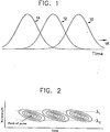
- Figure 1 is a graphical representation of the "spread-out" phenomenon, at the receiver of a receiving unit, which the inventors recognized and solved with the present invention.
- the overlapping of the pulse is called intersymbol interference.
- the figure shows a grouping of overlapped pulses in the time domain. In particular, time is represented on the horizontal axis and pulses 10, 12, and 14 are traveling in the direction of arrow 16.
- the broadening of the pulses causes overlap in both leading and trailing edges.
- the overlapping areas may be viewed as composite signals with energy that cannot be easily correlated with its associated pulses. Stated another way, the overlapping energy from adjacent pulses interferes with proper detection of the data.
- U. S. patents 4,538,283 and 4,555,789 disclose a type of intersymbol interference which causes the "eye" opening exhibited by pulses at the receiver to close, beginning at the corners and progressing towards the center. This phenomenon affects the sensitivity of the receiver to differentiate between a "0" and a "1".
- An equalizer circuit is used to restore the sensitivity of the receiver. It should be noted that these solutions are done in the electrical domain and are limited by the proximity of the carrier frequency to the data rate.
- the object of the invention is therefore to overcome the prior art limitations by operating in the optical domain, where the carrier frequency is many orders of magnitude greater than the data rate.
- each pulse into a central section, a leading edge section and a trailing edge section.
- the edge sections are adjusted in time and recombined with the central section to generate a recovered pulse with a reduction in overlapping edges.
- a fiber optic communications network includes at least a transmitting device interconnected by a fiber optic link to a receiving device.
- the transmitting device includes an edge-emitting LED (ELED) or a laser system with an approximately Gaussian wavelength distribution which generates a digital pulse stream that is transmitted through the interconnecting fiber optic link to the receiver of the receiving unit.
- ELED edge-emitting LED
- laser system with an approximately Gaussian wavelength distribution which generates a digital pulse stream that is transmitted through the interconnecting fiber optic link to the receiver of the receiving unit.
- the receiver includes an optical wavelength separator which separates each pulse into three pulse trains which are independently detected.
- One pulse train is composed of the energy from the bands of wavelengths which will be least delayed by the fiber and thus arrive early.
- Another pulse train comes from the band of wavelengths with medium fiber delay.
- the final pulse train comes from the band of wavelengths with maximum delay.
- the fastest pulse trains are delayed and recombined with the slow pulse train to output a reconstructed pulse.
- the reconstructed pulses are used to recover the information which was transmitted.
- Figure 1 shows a graphical representation of optical pulses overlapping in the time domain. The sketch is helpful in understanding the problem which the present invention solves.
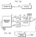
- Figure 2 shows a graphical representation of the pulses in a time/wavelength domain.
- FIG. 3 shows a simplified block diagram of a fiber optic communications network having an improved receiver embodying the teachings of the present invention.
- FIGS. 4-6 show pulses which are generated at different points of the receiver circuit. The pulses are helpful in understanding the operation of the improved receiver.
- Figure 2 shows a graphical representation of what the pulses in Figure 1 would look like if viewed with the added dimension of source wavelength.
- the sketches of Figure 2 are contour maps where the vertical dimensions in Figure 1 are now represented by flat contour lines.
- time is plotted on the horizontal axis while wavelength ( ⁇ ) is plotted on the vertical axis.
- the transmitter optical source (not shown) is assumed to have a Gaussian wavelength distribution. This sketch is helpful to understand the underlying principle of the present invention. When viewed in the wavelength/time domain, what appears to be overlap in Figure 1 is actually separable in the wavelength dimension.
- each pulse (Fig. 1) into its constituent wavelength bands. Therefore, wavelengths which are greater than ⁇ 1 are grouped into a first band.
- a second band includes the wavelengths that are between ⁇ 1 and ⁇ 2.
- the third band includes the wavelengths less than ⁇ 2.
- each pulse is separated into a plurality of pulse trains or its constituent pulse trains. Each pulse train is based upon the energy contained in the associated wavelengths.
- One pulse train is composed of energy from the band of wavelengths which is greater than ⁇ 1.
- a second pulse train is composed of energy from the band of wavelengths between ⁇ 1 and ⁇ 2.
- a third pulse train is based upon the energy from the band of wavelengths less than ⁇ 2.
- the pulses are divided into three pulse trains, this is only representative and it is within the skill of the art to separate each pulse into greater or less than three pulse trains.
- the speed with which a pulse is transmitted in the fiber depends on the wavelength characteristics of its constituents pulse trains. As a result, certain wavelength sections of the same pulse train are traveling faster than other sections. Having separated the pulse into its component wavelengths, the wavelengths which are traveling the fastest in the fiber are delayed at the receiver so that the portion of the pulse with the slower wavelengths will catch up. The respective sections of each pulse are then recombined to form a unified pulse which is outputted for use by the system.
- FIG 3A shows a communications system embodying the teachings of the present invention.
- the system includes a transmitter 18, a fiber optic communications network 20 and a receiver 22.
- the transmitter 18 includes an optical generator (not shown) which receives a data stream converts it to optical pulses which are transmitted by the fiber optics communications network 20 to receiver 22.
- pulses during transmission through the fiber optic communications network are spread out and arrive in overlapping orientation at receiver 22.
- the overlapping pulses are realigned and reconstructed.
- the receiver includes wavelength separator means 24 which receives the transmitted optical data stream from input fiber 21 and separates each pulse into a plurality of pulse trains.
- wavelength separator means 24 For example, pages 185 and 186 of a book entitled “Monomode Fiber Optic Design with Local Area and Long-Haul Network Applications," by Donald G. Baker, describes demultiplexers which could be used as wavelength separator means 24. It is well within the skill of one skilled in the art to use other types of wavelength separators without deviating from the spirit and teaching of the present invention. For completeness, the teachings of the referenced article are incorporated by reference.
- Each pulse train is composed of energy from the associated band of wavelengths. Thus, with reference to Figure 2, wavelengths which are greater than ⁇ 1 are grouped into one pulse train.
- a second pulse train is composed of energy from the band of wavelengths between ⁇ 1 and ⁇ 2.
- a third pulse train is composed of the energy from the band of wavelengths less than ⁇ 2.
- the pulse train which is in the wavelength band that is greater than ⁇ 1 is fed over fiber optic conductor 26 to optical-to-electrical (O/E) converter 28.
- the pulse train which is composed of the energy from the band of wavelengths between ⁇ 1 and ⁇ 2 are fed over optical fiber conductor 30 to optical-to-electrical (O/E) converter 32.
- pulse train that is composed of the energy from the band of wavelengths less than ⁇ 2 is fed over optical fiber conductor 34 to optical-to-electrical (O/E) converter 36.
- the optical-to-electrical converters (OE) 28, 32 and 36 convert the optical pulse to electrical signals which are fed to electrical conductors A, B and C respectively.
- the pulse trains that are derived from the energy band of wavelengths greater than ⁇ 1 and between ⁇ 1 and ⁇ 2 are traveling faster than the pulse train that is composed of energy from the band of wavelength less than ⁇ 2.
- the pulses on conductors A and B are delayed by delay means 38 and 40, respectively.
- the delayed signal from delay means 38 is fed over conductor D to summing amplifier 39.
- the delayed pulse train from delay means 40 is fed over conductor E to summing amplifier 39.
- the pulse train from O/E 36 is fed over conductor C to summing amplifier 39.
- Summing amplifier 39 recombines the pulse train to form a unified pulse which is outputted on conductor G.
- the pulse on conductor G is fed into threshold means 41 which output are pulsed to terminal Vout if its input exceeds a predetermined level.
- Figures 4-6 give graphical representation of pulses as they are processed and appear at respective points on the circuit of Figure 3. These graphs are helpful in understanding the operation of the circuit shown in Figure 3. Also, like alphabetical characters are used to identify the pulses (Figs 4-6) and the conductors (Fig. 3B) on which they are transmitted.
- the output signals of the optical-to-electrical converters 28, 32 and 36 on conductors A, B and C for each data stream are shown in Figure 4.
- the curve labeled A in Figure 4 represents the pulse train for the section of the pulse appearing on conductor A (Fig. 3B).
- the curve labeled C represents the portion of the pulse appearing on conductor C.
- the pulse labeled B represents the pulse train representing the center section of the pulse and appears on conductor B.
- the relative delays in the data stream corresponds to the optical velocity for the optical wavelengths in each data stream.
- the amplitudes are lower in the side data streams (A and C, Fig. 4) because the transmitter produces less energy at these wavelengths.
- the resulting data streams D, E and F (Fig. 5), at the input to summing amplifier 39 are brought into phase.
- the sum of these signals, at the output of summing amplifier 39 is a data stream in which the interfering skirts or edges of the pulses have been shifted so that the inter-symbol interference is decreased.
- the signal can be digitized in threshold detector 41 with less interference from adjacent pulses.
- the dashed pulse in Figure 6 represents the original pulse which was inputted by the transmitter (Fig. 3B) while the pulse with the solid line represents the final reconstructed pulse. It should be noted that the final reconstructed pulse is narrower but has a higher amplitude than the original pulse that was transmitted into the communications network 20.
- the three data stream systems shown can be expanded to multiple data streams, each with a particular band of wavelengts and particular delay line so that the chromatic dispersion related inter-symbol interference can be reduced to as small an effect as is desired.
- Wavelength filtering, analog delay lines, optical-to- electrical converters and amplifiers have all been demonstrated in integrated circuits (IC) form. It is expected that this system could also be fabricated in IC form.
Landscapes
- Physics & Mathematics (AREA)
- Electromagnetism (AREA)
- Engineering & Computer Science (AREA)
- Computer Networks & Wireless Communication (AREA)
- Signal Processing (AREA)
- Optical Communication System (AREA)
- Light Guides In General And Applications Therefor (AREA)
Applications Claiming Priority (2)
| Application Number | Priority Date | Filing Date | Title |
|---|---|---|---|
| US586644 | 1990-09-24 | ||
| US07/586,644 US5191627A (en) | 1990-09-24 | 1990-09-24 | Reduction of intersymbol interference in optical fiber systems by wavelength filtering |
Publications (2)
| Publication Number | Publication Date |
|---|---|
| EP0478484A2 true EP0478484A2 (de) | 1992-04-01 |
| EP0478484A3 EP0478484A3 (en) | 1992-09-16 |
Family
ID=24346577
Family Applications (1)
| Application Number | Title | Priority Date | Filing Date |
|---|---|---|---|
| EP19910480125 Withdrawn EP0478484A3 (en) | 1990-09-24 | 1991-08-13 | Fiber optic communication network with reduction of intersymbol interference |
Country Status (3)
| Country | Link |
|---|---|
| US (1) | US5191627A (de) |
| EP (1) | EP0478484A3 (de) |
| JP (1) | JPH04227138A (de) |
Cited By (2)
| Publication number | Priority date | Publication date | Assignee | Title |
|---|---|---|---|---|
| GB2277652A (en) * | 1993-04-30 | 1994-11-02 | Ericsson Telefon Ab L M | Chromatic dispersion compensation |
| CN106716942A (zh) * | 2014-10-23 | 2017-05-24 | 英特尔公司 | 用于数字地消除串扰的装置和方法 |
Families Citing this family (5)
| Publication number | Priority date | Publication date | Assignee | Title |
|---|---|---|---|---|
| US5367586A (en) * | 1993-03-26 | 1994-11-22 | At&T Bell Laboratories | Optical delay line |
| JPH1063350A (ja) * | 1996-08-14 | 1998-03-06 | Kokusai Denshin Denwa Co Ltd <Kdd> | 光周波数安定化装置 |
| US6632033B1 (en) * | 1999-04-13 | 2003-10-14 | Cisco Technology, Inc. | Ultra-short reach optical communications system and method of manufacture |
| US7181097B2 (en) * | 2001-03-15 | 2007-02-20 | Massachusetts Institute Of Technology | Methods of achieving optimal communications performance |
| US7218808B2 (en) * | 2004-09-09 | 2007-05-15 | Agency For Science, Technology And Research | Equalizer circuit for a light source |
Family Cites Families (8)
| Publication number | Priority date | Publication date | Assignee | Title |
|---|---|---|---|---|
| US3699445A (en) * | 1970-11-02 | 1972-10-17 | Bell Telephone Labor Inc | Frequency shift keyed communication system |
| DE2432718A1 (de) * | 1974-07-08 | 1976-01-29 | Siemens Ag | Verfahren und vorrichtung zur breitbandigen uebertragung optischer wellen |
| JPS574881A (en) * | 1980-06-07 | 1982-01-11 | Hitachi Ltd | Safety device for automatic door of elevator |
| DE3317541A1 (de) * | 1983-05-13 | 1984-11-15 | Siemens AG, 1000 Berlin und 8000 München | Koppeleinrichtung fuer einen lichtwellenleiter |
| SE438396B (sv) * | 1983-09-01 | 1985-04-15 | Ericsson Telefon Ab L M | Anordning for att detektera avtappning av ljusenergi fran optiska fibrer |
| US4750802A (en) * | 1986-08-08 | 1988-06-14 | Corning Glass Works | Optical fiber dispersion compensator |
| US4778239A (en) * | 1987-02-02 | 1988-10-18 | Litton Systems, Inc. | Feed-backward lattice architecture and method |
| GB8708148D0 (en) * | 1987-04-06 | 1987-05-13 | British Telecomm | Radiation pulse generation |
-
1990
- 1990-09-24 US US07/586,644 patent/US5191627A/en not_active Expired - Fee Related
-
1991
- 1991-07-16 JP JP3201256A patent/JPH04227138A/ja active Pending
- 1991-08-13 EP EP19910480125 patent/EP0478484A3/en not_active Withdrawn
Cited By (5)
| Publication number | Priority date | Publication date | Assignee | Title |
|---|---|---|---|---|
| GB2277652A (en) * | 1993-04-30 | 1994-11-02 | Ericsson Telefon Ab L M | Chromatic dispersion compensation |
| US5522004A (en) * | 1993-04-30 | 1996-05-28 | Telefonaktiebolaget Lm Ericsson | Device and method for dispersion compensation in a fiber optic transmission system |
| GB2277652B (en) * | 1993-04-30 | 1997-07-16 | Ericsson Telefon Ab L M | Device and method for dispersion compensation in a fibre optic transmission system |
| CN106716942A (zh) * | 2014-10-23 | 2017-05-24 | 英特尔公司 | 用于数字地消除串扰的装置和方法 |
| CN106716942B (zh) * | 2014-10-23 | 2020-08-11 | 英特尔公司 | 用于数字地消除串扰的装置和方法 |
Also Published As
| Publication number | Publication date |
|---|---|
| JPH04227138A (ja) | 1992-08-17 |
| US5191627A (en) | 1993-03-02 |
| EP0478484A3 (en) | 1992-09-16 |
Similar Documents
| Publication | Publication Date | Title |
|---|---|---|
| EP0197263B1 (de) | Verfahren und Gerät zur Ausrichtung von WDM-Daten, übertragen durch ein dispersives Medium | |
| US6366373B1 (en) | Method of intrinsic continuous management data transmission in fiber optic communications | |
| US5483372A (en) | Single and multichannel transmission over long distances using repeated level-crossing remodulation | |
| US5401957A (en) | Optical waveform shaping device for peforming waveform equalization and timing synchronization | |
| US6538786B1 (en) | Optical communication system and optical reception apparatus using synchronous polarization scrambler | |
| CN105553560A (zh) | 基于光强度调制信号的偏振无关直接检测系统及方法 | |
| GB2240228A (en) | Optical transmission system | |
| US5191627A (en) | Reduction of intersymbol interference in optical fiber systems by wavelength filtering | |
| EP0555063B1 (de) | Vorrichtung zur optischen Wellenformung | |
| JP2583474B2 (ja) | 光多重分離装置 | |
| KR100584351B1 (ko) | 듀오바이너리 인코더 및 이를 이용한 광 듀오바이너리전송장치 | |
| EP1271993A2 (de) | Leitweglenkungssystem mit rein optischer Vermittlung | |
| EP1408631B1 (de) | Optischer Sender | |
| CA2351808C (en) | A method and apparatus for demultiplexing high bit rate optical signals on a dense wavelength grid | |
| Moscoso-Mártir et al. | Silicon photonics DWDM NLFT soliton transmitter implementation and link budget assessment | |
| KR100296385B1 (ko) | 전송 속도 인식방법 및 그 장치 | |
| US6795653B1 (en) | Apparatus for reshaping optical pulses | |
| US7099593B1 (en) | Self-synchronization of an optical packet network using seed pulses extracted from within the packets | |
| EP4482061A1 (de) | System und verfahren zur datenübertragung mit einem gemeinsamen detektionsempfänger | |
| KR100376597B1 (ko) | 광파장 분할 시스템에서 시분할 톤 주파수 변조방식을이용한 광채널 모니터 시스템 | |
| US20090129789A1 (en) | Method and Apparatus for Extracting Clock Signal From Optical Signal | |
| EP1057298B1 (de) | Selbst-synchronisierung eines optischen paketnetzwerkes durch ursprungspulse, die aus den paketen gewonnen wurden | |
| CN101091343A (zh) | 用于在光通信系统中减缓色散斜率的系统和方法 | |
| JPH0392829A (ja) | 光クロック信号抽出装置 | |
| JPH047618B2 (de) |
Legal Events
| Date | Code | Title | Description |
|---|---|---|---|
| PUAI | Public reference made under article 153(3) epc to a published international application that has entered the european phase |
Free format text: ORIGINAL CODE: 0009012 |
|
| AK | Designated contracting states |
Kind code of ref document: A2 Designated state(s): DE FR GB |
|
| PUAL | Search report despatched |
Free format text: ORIGINAL CODE: 0009013 |
|
| AK | Designated contracting states |
Kind code of ref document: A3 Designated state(s): DE FR GB |
|
| 17P | Request for examination filed |
Effective date: 19920817 |
|
| 17Q | First examination report despatched |
Effective date: 19941010 |
|
| STAA | Information on the status of an ep patent application or granted ep patent |
Free format text: STATUS: THE APPLICATION IS DEEMED TO BE WITHDRAWN |
|
| 18D | Application deemed to be withdrawn |
Effective date: 19950421 |