EP0478687B1 - Recipient, notamment pour produits coulants - Google Patents
Recipient, notamment pour produits coulants Download PDFInfo
- Publication number
- EP0478687B1 EP0478687B1 EP90910681A EP90910681A EP0478687B1 EP 0478687 B1 EP0478687 B1 EP 0478687B1 EP 90910681 A EP90910681 A EP 90910681A EP 90910681 A EP90910681 A EP 90910681A EP 0478687 B1 EP0478687 B1 EP 0478687B1
- Authority
- EP
- European Patent Office
- Prior art keywords
- slide
- lid
- container according
- catch
- closed position
- Prior art date
- Legal status (The legal status is an assumption and is not a legal conclusion. Google has not performed a legal analysis and makes no representation as to the accuracy of the status listed.)
- Expired - Lifetime
Links
- 239000011324 bead Substances 0.000 claims description 27
- 210000001331 nose Anatomy 0.000 claims description 20
- 230000009471 action Effects 0.000 claims description 13
- 210000002105 tongue Anatomy 0.000 claims description 12
- 238000006073 displacement reaction Methods 0.000 claims description 3
- 238000002347 injection Methods 0.000 claims description 3
- 239000007924 injection Substances 0.000 claims description 3
- 238000010276 construction Methods 0.000 claims description 2
- 238000004806 packaging method and process Methods 0.000 description 11
- 239000000463 material Substances 0.000 description 10
- 239000000243 solution Substances 0.000 description 4
- 239000003599 detergent Substances 0.000 description 3
- 230000001960 triggered effect Effects 0.000 description 3
- 230000008901 benefit Effects 0.000 description 2
- 239000002131 composite material Substances 0.000 description 2
- 238000001746 injection moulding Methods 0.000 description 2
- 230000007246 mechanism Effects 0.000 description 2
- 230000004048 modification Effects 0.000 description 2
- 238000012986 modification Methods 0.000 description 2
- 239000000853 adhesive Substances 0.000 description 1
- 238000004026 adhesive bonding Methods 0.000 description 1
- 230000001070 adhesive effect Effects 0.000 description 1
- 230000000903 blocking effect Effects 0.000 description 1
- 238000004851 dishwashing Methods 0.000 description 1
- 230000000694 effects Effects 0.000 description 1
- 231100001261 hazardous Toxicity 0.000 description 1
- 210000003128 head Anatomy 0.000 description 1
- 239000012943 hotmelt Substances 0.000 description 1
- 238000004519 manufacturing process Methods 0.000 description 1
- 238000007789 sealing Methods 0.000 description 1
- 238000007493 shaping process Methods 0.000 description 1
- 230000007704 transition Effects 0.000 description 1
- 230000003313 weakening effect Effects 0.000 description 1
Images


Classifications
-
- B—PERFORMING OPERATIONS; TRANSPORTING
- B65—CONVEYING; PACKING; STORING; HANDLING THIN OR FILAMENTARY MATERIAL
- B65D—CONTAINERS FOR STORAGE OR TRANSPORT OF ARTICLES OR MATERIALS, e.g. BAGS, BARRELS, BOTTLES, BOXES, CANS, CARTONS, CRATES, DRUMS, JARS, TANKS, HOPPERS, FORWARDING CONTAINERS; ACCESSORIES, CLOSURES, OR FITTINGS THEREFOR; PACKAGING ELEMENTS; PACKAGES
- B65D50/00—Closures with means for discouraging unauthorised opening or removal thereof, with or without indicating means, e.g. child-proof closures
- B65D50/02—Closures with means for discouraging unauthorised opening or removal thereof, with or without indicating means, e.g. child-proof closures openable or removable by the combination of plural actions
- B65D50/04—Closures with means for discouraging unauthorised opening or removal thereof, with or without indicating means, e.g. child-proof closures openable or removable by the combination of plural actions requiring the combination of simultaneous actions, e.g. depressing and turning, lifting and turning, maintaining a part and turning another one
- B65D50/045—Closures with means for discouraging unauthorised opening or removal thereof, with or without indicating means, e.g. child-proof closures openable or removable by the combination of plural actions requiring the combination of simultaneous actions, e.g. depressing and turning, lifting and turning, maintaining a part and turning another one where one action elastically deforms or deflects at least part of the closure, the container or an intermediate element, e.g. a ring
-
- B—PERFORMING OPERATIONS; TRANSPORTING
- B65—CONVEYING; PACKING; STORING; HANDLING THIN OR FILAMENTARY MATERIAL
- B65D—CONTAINERS FOR STORAGE OR TRANSPORT OF ARTICLES OR MATERIALS, e.g. BAGS, BARRELS, BOTTLES, BOXES, CANS, CARTONS, CRATES, DRUMS, JARS, TANKS, HOPPERS, FORWARDING CONTAINERS; ACCESSORIES, CLOSURES, OR FITTINGS THEREFOR; PACKAGING ELEMENTS; PACKAGES
- B65D50/00—Closures with means for discouraging unauthorised opening or removal thereof, with or without indicating means, e.g. child-proof closures
- B65D50/02—Closures with means for discouraging unauthorised opening or removal thereof, with or without indicating means, e.g. child-proof closures openable or removable by the combination of plural actions
- B65D50/06—Closures with means for discouraging unauthorised opening or removal thereof, with or without indicating means, e.g. child-proof closures openable or removable by the combination of plural actions requiring the combination of different actions in succession
- B65D50/067—Closures with means for discouraging unauthorised opening or removal thereof, with or without indicating means, e.g. child-proof closures openable or removable by the combination of plural actions requiring the combination of different actions in succession using integral or non-integral accessories, e.g. tool, key
Definitions
- the invention relates to a container for in particular free-flowing, intended for consumption products with a hull that has an inwardly folded bead on its open side, a lid attached to it, a removal opening and a closure member in the form of a slide with a handle that consists of a Open position can be brought into a closed position in which it is locked by means of a lock acting as a child lock.
- a container for in particular free-flowing, intended for consumption products with a hull that has an inwardly folded bead on its open side, a lid attached to it, a removal opening and a closure member in the form of a slide with a handle that consists of a Open position can be brought into a closed position in which it is locked by means of a lock acting as a child lock.
- a container is known from DE-A-36 43 600.
- Packaging containers with a removal opening which can be closed by a slide, in particular on the lid of the packaging container are known.
- the removal opening can only make up a part of the lid and can be used, for example, as a sprinkling opening, metering opening or the like for removing partial quantities, or can also be designed as a full opening if, for example, the filling material is to be removed in one go and decanted or the contents are removed in portions by reaching into the container.
- the slide covers only a partial area on the cover, in the latter case it essentially forms the closure cover itself.
- Such a slide can be designed as a linear slide or - especially in the former case - as a rotary slide.
- Packaging containers of this type serve primarily to hold free-flowing products and can be any, in particular also a different from the circular shape, for. B. have substantially rectangular cross-section.
- Packaging containers of this type often contain contents which have health-impairing or hazardous properties. This applies, for example, to household cleaners, detergents or the like. Such products, in particular, must not be accessible to small children.
- a lock e.g. DE-A-36 43 600
- the locking is generally such that it is alone is overcome by the opening movement, be it a linear sliding movement or a rotary movement. Adequate child protection is not provided.
- US-A-3 240 373 in that the lock can only be actuated with an additional tool, which is, however, cumbersome.
- the invention has for its object to provide a packaging container of the aforementioned construction with an all-round bead at the opening edge with an effective child safety device.
- the cover on approximately opposite sides has the bulges engaging noses, of which at least part of the slide is guided on the cover and between the closed position in which the cover is fixed to the fuselage and the lock is engaged , can be moved into the open position by means of the handle accessible on the top of the lid and after actuation of the catches, in which the lid can be lifted off by releasing the entire open side of the fuselage.
- the lid can have the basic shape known from loose slip lids, namely have an edge flange overlapping the container body on the open side with an inwardly drawn-in cover disk.
- the edge flange is only to be designed so that it overlaps the bead, possibly with a little pretension.
- the cover in the region of the edge flange has at least two approximately opposite lugs, at least one of which is designed as a slide or is part of one which is operated by means of the handle is movable between an open position and a closed position.
- the lid In the open position, the lid is placed on the bead, possibly inserted at an incline so that the nose can reach under the bead, and the slide is then moved into the closed position so that he or his nose also pushes the bead on the opposite side Reaches under.
- the slide can be guided on the underside of the cover by guide elements molded onto the cover.
- the lid In the closed position of the slide, the lid is connected to the fuselage and the slide is at the same time latched onto the lid, so that even if the container tips over or is lifted, contents cannot escape on the lid.
- the lid can only be separated from the fuselage by consciously manipulating the handle that moves the slide and by unlocking the lock.
- the open position the entire cross-section of the container is exposed, so that the contents can be removed not only by pouring, but also by means of a portioning vessel.
- An advantageous embodiment of the invention is characterized in that at least the nose opposite the slide, which is firmly connected to the cover, is designed as a spring latching nose engaging under the bead on the fuselage.
- the cover only needs to be pressed onto the bulge of the fuselage when the slider is retracted, the nose engaging automatically.
- the nose of the slide is designed as a spring catch so that the cover only has to be pressed onto the fuselage regardless of the position of the slide, but in particular even when the slide is closed. This is especially true for the bottling plant the advantage that the lid supplied in or behind the filling station can be placed easily, if necessary by machine.
- the spring catches only spring out when the cover is put on and engage behind the bead under tensile forces acting on the cover, so that the container can be lifted on the cover without the latter becoming detached.
- the lock has at least two detents arranged at a distance from one another, but in the grip area of the fingers of one hand, which are effective in the closed position of the slide and can only be released with at least two fingers for opening the same.
- the slide is held in the closed position by at least two notches. These two catches must be pressed simultaneously in order to be able to move the slide, in particular to lead it into the open position.
- the catches are designed and arranged in such a way that at least two fingers are necessary to release the catches and to be able to move the slide.
- the movement of the slide itself can then not be carried out with the same hand, but the user must also use the second hand. A toddler cannot easily understand these considerations.
- the securing can be further improved in that the catches are arranged at such a distance from one another that the span to be bridged for the simultaneous attachment of two fingers is greater than the possible span of two fingers of a child's hand. In this case, a toddler has no option to open the slide due to the two-handed operation required.
- the rest can held in any position in the closed position and brought into the unlocked position, for example by pulling, pressing, turning or the like.
- the two catches can be offset next to one another on a line perpendicular to the direction of movement of the slider or one behind the other or in alignment in the direction of movement of the slider.
- the type of arrangement depends primarily on the shape and size of the container and the aspects to be observed for the removal opening and its arrangement.
- the catches at the same time form an effective protection against untimely opening, for example by inadvertent action on the slide, by bumping, tipping over or the like.
- This solution principle can be implemented constructively, for example, by the two catches being effective one after the other in the direction of movement of the slide.
- the two catches are arranged and designed so that one catch is only effective in the closed position, the other in the direction of movement of the slide between the closed position and the intermediate position.
- both detents are effective in the closed position. If they are pressed simultaneously with two fingers and only for a short time, one of the catches is triggered, but the other remains effective and must either be pressed continuously until the intermediate layer is reached or must be pressed again in the intermediate layer.
- a preferred embodiment provides that the catches are formed from openings arranged on the slide or on the cover and approximately of the same shape and serving as actuators for resiliently locking cams.
- This embodiment can be realized constructively, for example, in that the actuators are arranged on resilient tongues.
- the usual locking of the slide in the closed position can be dispensed with, since this task can be performed by at least one of the catches.
- the design can be such that in the closed position of the slide an actuating member engages in an opening on the slider, while the second actuating member and the second opening are disengaged and only engage in the intermediate position.
- one of the projections must first be pressed into the opening so that the slide can be moved into the intermediate layer.
- the second projection engages in the second opening and must be actuated by a further finger pressure in order to finally bring the slide into the open position.
- one opening is of the same shape as the actuating member, the other is an elongated hole extending in the direction of movement of the slide between the closed position and the intermediate position.
- the one projection remains within the elongated hole until the slide moved out of the closed position has reached the intermediate position. To open it is therefore necessary to either press both actuators at the same time and to allow the pressure on the actuating member guided in the elongated hole to last until the intermediate position, or to actuate the actuating member again so that the slide can only then be moved into the open position.
- a further embodiment consists in that the lock is formed by at least one cam which is resiliently arranged on the cover and a locking surface on the slide cooperating with it, and in that the cam also forms the actuating element for the lock.
- the blocking surface on the slide can in turn be an opening into which the cam engages, or else a simple stop surface, for example on the end of the slide facing away from the bead, behind which the cam engages in the closed position.
- the cam or its actuating member can be brought into a position releasing the lock by a pulling or pushing movement.
- the spring action can be obtained from the elasticity of the material of the cover or slide or by appropriate shaping thereof.
- the lock is formed by at least one toothed bar arranged on the underside of the cover and a corresponding toothed bar arranged on the slide, the latter being able to be disengaged against the spring action by means of an actuating member.
- the toothed strips can have an asymmetrical tooth profile, for example be designed like a saw tooth, so that, for example, actuation of the lock is not necessary for closing the slide.
- the teeth slide away from one another, but fulfill their locking function when the slide is in the opposite direction.
- An embodiment of this embodiment is characterized in that the toothed strip on the cover lies in a plane parallel to the cover surface and that the actuating member for the other toothed strip on the slide also forms its handle.
- the actuator for the lock and the handle for the slide coincide.
- the actuator To open the slide, the actuator must first be pressed down to disengage the toothed strips. Then a sliding movement must then be effective on the actuator to move the slide from the closed position and to be able to lift the lid.
- the lock can also be designed such that the toothed strip on the cover lies in a plane perpendicular to the cover surface.
- the toothed strips are advantageously arranged so that the actuating movement for releasing the lock and for moving the slide are perpendicular to one another, so that two-hand operation is necessary in any case.
- this embodiment can be modified such that two toothed strips are provided at a distance from one another and with the teeth facing each other and that two toothed strips with one another on the slide turned toothings are provided, which are forced outwards under the spring action into the toothed strips on the cover and come out of engagement by means of two actuating members to be pressed against one another with one hand.
- the actuating members of the two toothed strips are pressed toward one another, for example, with the fingers of one hand and the handle of the slide is actuated with the other hand.
- the slide is held by a spring in the closed position, which is designed as a resilient kink support with dead center position, in which the slide is held in the closed position, and that the kink support also serves as a lock by the The crest of the kink support forms the actuating element of the lock and can be brought into an unstable position by pressure via the dead center position, in which the slide can be moved by means of the handle.
- Such an anti-kink support gives the possibility of injecting the slide directly in one piece with the cover, for example via so-called film hinges.
- the kink support has a stable position in its one kink position, in which the slide is in the closed position. The slide can therefore only be moved into the open position while overcoming the dead center position. By pressing on the top of the kink, the kink support can be brought over the dead center position into the other kink position, in which it is unstable due to the articulated film hinges, so that the slide can be moved into the open position.
- two slides can be provided, each with a handle, each of which is assigned a lock.
- both locks must be released in order to be able to move the slide into the open position.
- Containers of the aforementioned type in particular large household packs, generally have a handle which is pivotally mounted, for example, on the body of the container or on the lid.
- the handle also forms part of the lock for the slide and the lock can be released by means of the pivoting movement of the handle.
- the handle is therefore used for a further purpose by simultaneously serving as part of the child safety device.
- the lock has a cam which is resiliently arranged on the cover or on the slide and which engages in a receptacle which is arranged on the cover and is open at the top, and in that the handle is pivoted with a section into the receptacle, displacing the cam is insertable.
- This also provides an extremely effective child safety device, in that the handle, which is obviously used for other purposes, is used for a purpose that is not intended for it and is also not foreseeable by a small child.
- the aforementioned securing is particularly effective when the handle, as usual, has a band-shaped cross section, and also the receptacle is correspondingly slit-shaped.
- the slot forming the receptacle can be so narrow and, in this case, the ledge-shaped cam can be recessed in the receptacle so that it is impossible to actuate the cam by hand, ie it can only be operated by the carrying handle or a correspondingly narrow auxiliary tool the recording can be suppressed.
- containers of the aforementioned type are bulk packaging, they must be correspondingly inexpensive to manufacture.
- the lock is connected via a joint to the cover or the slide and is injection-molded together in one piece with them.
- a one-piece injection molding of this relatively complicated structure of cover, slide and lock with handle, actuating member and guides can be easily achieved by means of an injection molding tool, in which the cover and slide are sprayed in different planes converging in the joints.
- the lid of the container forms, together with the slide, a uniform component that can be retrofitted to the container body.
- this component can be retrofitted as a whole to the open end of a container, for. B. flanging, gluing or sealing.
- the cover has at least on two opposite sides of guide surfaces lying one above the other, between which the slide is movable.
- the guide surfaces are preferably in one piece with the container lid.
- the cover can have an annular flange which can be connected to the container body and a wall covering the free cross section of the container body up to the removal opening, the slide being in the open position approximately above this wall and this having the tongues with the actuating members.
- the removal opening thus takes up only a part of the cross section of the container, and is therefore primarily used for portioned removal of the filling material by pouring.
- the lid is essentially designed as an annular flange, the two circumferential projecting into the free cross-section of the container body and the guide surfaces for the Has slide forming guide strips, and that on one of the lower guide strips, the tongues with the actuators and corresponding openings are arranged on the upper guide bar above, which are aligned with the openings in the slide in its closed position and how these are penetrated by the actuators.
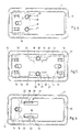
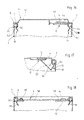
- the container 1 consists of a body 2 with a rectangular cross section in the exemplary embodiment shown, a bottom 3 which closes the body 2 on one side and is drawn inwards, a cover 4 which closes the opposite opening and a carrying handle 5 which is by means of Rivets 6 is pivotally mounted on the fuselage 2.
- the container serves, for example, as a large household pack for detergents, dishwashing detergents or the like.
- the fuselage 2 has an inwardly folded bead 7 at the opening opposite the bottom 3, as can be seen in more detail in FIGS. 2 and 3.
- the bead 7 is formed all around and initially stiffens the fuselage 2 in the area of the opening. In addition, it serves to attach the cover 4.
- the cover 4 has an edge flange 8 which overlaps the bead 7 from above and a lower-lying cover plate 9 which are formed in one piece. Furthermore, the lid has a nose 10, 11 that engages under the bead 7 on approximately opposite sides.
- the nose 11 is only designed as a slide 12 which is guided linearly in guides 13 on the underside of the cover plate 9 and has a handle 14 which projects upwards through an opening in the cover plate.
- the guide 13 can be formed, for example, by spring noses 15 molded onto the underside of the cover plate 9, which engage in parallel slots in the slide 12.
- the cover 4 To put on the cover 4, this is first placed in an inclined position with the nose 10 ahead on the left part of the fuselage, so that the nose 10 engages under the bead 7 there. Then the cover 4 is tilted downwards to the right and placed on the bead 7 and finally the slide 12 is moved back into the closed position. For this purpose, the handle 14 is guided in an elongated hole 16 (see FIG. 4) in the cover plate 9.
- the lock consists of two catches, each of which is formed by a cam 18 in the form of a pushbutton and an opening 19 arranged in the cover plate 9, into which the spring-loaded cam 18 engages.
- the cam 18 is part of the slide 12, the spring action being obtained from the material elasticity of the slide 12. The distance the cam 18 from each other and from the handle 14 of the slider 12 can be selected so that the slider 12 can only be opened with two hands, for example by pressing the cams 18 down with two fingers of one hand and the slider 12 with the other hand is moved by means of the handle 14.
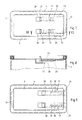
- both lugs 10, 11 are formed as part of a slide 12 and are guided separately from one another in guides 13 on the cover 4. They can be actuated by means of a handle 14 in the same way as the slide 12 according to FIGS. 1 to 4.
- Each slide 12 is assigned two locks 17, which, however, act collectively on both slides.
- the locks 17 in turn have cams 18 which pass through openings 19 in the cover plate 9.
- the cams 18 are part of strips 20 which are held under spring action in the locked position and act against stop surfaces 21 on the slides 12. By pressing the cams 18, the strips 20 disengage from the stop surfaces 21 so that the slides 12 can be opened. Consequently, the cams 18 must first be pressed with one hand and then the handles 14 can be grasped with the spread fingers of one hand and pulled against one another in order to move the slides 12 into the open position.
- the locks 17 consist of a toothed strip 22 which is arranged on the underside of the cover or in openings in the cover 4, the toothing of which is facing one another and is essentially perpendicular to the cover plane.
- Corresponding toothed strips are hereby arranged on the slide 12 via resilient arms 23, each of which has an actuating member 18 which extends through the cover plate 9 upwards.
- the spring action of the arms 23 is designed such that the toothed racks formed on them engage the toothed racks 22 on Lid 4 are held.
- the slide 12 is again assigned two locks 17, which in turn are designed as toothed strips 24.
- the toothed strips 24 are arranged in a plane parallel to the cover plate 9 on the underside of the cover 4.
- Toothed slats 25 are in turn formed by resilient arms 25 toothed strips 26, which engage with the toothed strips 24 on cover 4 under the action of the spring force.
- a handle 27 is arranged, which reach up through openings 28 in the cover plate 9.
- the handles 27 also form the actuators for the locks 17. By pressing the handles 27, the lock is first released and then the slide 12 is brought into the open position by thrust.
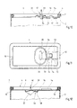
- two sliders 29 arranged parallel to one another are provided, the handle 30 of which in turn engages through openings 31 in the cover plate 9.
- a lock 17 is provided on each slide, which is formed, for example, from a slot 31 formed in the cover plate 9 and a strip 32 engaging therein on the slide.
- the slide 12 is again seated in guides 13 and a handle 14 formed on it extends through an elongated hole 16 in the cover plate 9.
- the lock 17 is of a type which also has the actuating member Cam 33 formed, which cooperates with a locking surface 34 on the side opposite the closing edge of the slide.
- the cam 33 is integrally formed on the cover plate 9, specifically on a section 35 which is curved downward and is prestressed in this direction and which urges the cam 33 into the locked position. By pulling the cam 33, the locking surface 34 of the slide 12 is released and the slide can be moved into the open position by means of the handle 14.
- the slide 12 is injection molded onto the cover 4 via an articulated support 36.
- the slide 12 also has the handle 14, which in turn engages in an elongated hole 16 on the cover plate 9, but in this case is additionally guided, for example in longitudinal slots, on the cover plate 9.
- the kink support 36 with the legs 37, 38 which merge into one another in the kink apex 39 has a stable position, which is shown in solid lines in FIG. In this stable position, the slide 12 in the closed position cannot be moved by means of the handle 14. By pressing on the top of the kink, as indicated by direction arrow 40, the kink support 36 can be bent downward (indicated by dash-dotted lines).
- the two legs 37, 38 can be folded towards one another, so that the slide 12 can be guided into the open position and the cover 4 can be removed. If the slide 12 is moved into the closed position when the cover 4 is in place, the kink support 36 automatically snaps into the stable position according to FIG.
- the exemplary embodiment according to FIGS. 13 and 14 has a handle 5, which, however, in a modification to the illustration in FIG. 1, is not articulated on the body 4 of the container, but on the lid 4 in bearings 41.
- the bearings 41 are located on the mutually facing inner sides of the edge flange 8 of the lid 4.
- the handle is designed so that it, as from 13 and 14 can be seen, when folding onto the cover lies within the edge flange 8.
- the band-shaped handle 5 also serves as an aid for opening the lock of the slide.
- the slider 12 is in turn guided in guides 13 on the underside of the cover and provided with a handle 14 extending through it upwards.
- the lock 17 is formed in this case by a strip-shaped cam 42 on the slide 12 and a slot-shaped receptacle 43, in which the cam 42 engages in the closed position.
- the slot-shaped receptacle 43 can be designed so that the cam 42 does not protrude above it.
- the slide 12 is designed as a rotary slide 45 which is mounted on an axis 46 arranged on the cover 4.
- the rotary valve 45 is circular in the embodiment shown and forms the closing edge or closing surface with the partially circular surface 47, while by turning the edge 48 formed by a circular edge is brought in parallel to the bead 7, in which the lid can be lifted off.
- the cover has a part-circular opening 49 into which a handle arranged on the rotary slide 45 engages. Protection against rotation, as indicated in FIG. 15, can be obtained by an additional toothing of the rotary valve with the underside of the cover, so that opening is only possible by pushing and pushing on the handle 14.
- other types of Use the childproof lock as described above in connection with the rotary valve 45 can be obtained by an additional toothing of the rotary valve with the underside of the cover, so that opening is only possible by pushing and pushing on the handle 14.
- the lugs 10, 11 are designed in such a way that the cover 4 can only be put on when the slide 12 is open and the lug 10 must be guided under the bead 7 with the cover being inclined
- the nose 10 arranged on the cover 4 and the nose 11 provided on the slide are designed as spring locking noses 50, 51.
- the spring latch 50 is formed on the cover 4 and is designed as a downwardly extending spring strut with a bend 520, with which the spring latch engages under the bead 7.
- the spring catch 51 which is designed in the same way, is formed on the slide 12.
- the cover plate 52 is also pulled upwards relative to the edge flange 8.
- the transition between the edge flange 8 and the cover plate 52 forms a stacking aid when the sealed containers are placed one on top of the other.
- the cover plate 52 has a slot 53, below which the slide 12 is guided, for example on a rib 54.
- the handle 14 of the slide 12 is accessible through the slot 53.
- the inwardly rolled bead 7 of the fuselage 2 is only fastened to the inside of the fuselage 2 with an adhesive, hot melt or the like at the points where it is under the noses 10, 11.
- the aforementioned embodiment has the advantage that the cover 4 - regardless of the position of the slide 12 - after attachment to the bead 7 is fixed only by pressure on the fuselage, the spring detents 50, 51 springing inwards and then with their kinked apex 52 underneath engage the bead 7.
- the spring catch 51 formed on the slide 12 is also connected to the cover 4. It in turn has a kink apex 52 which engages under the bead 7.
- the spring catch 51 also forms a spring 56 which urges the slide 12 into the closed position, in which, for example, a film hinge obtained by material weakening is provided at 57, which always keeps the spring catch 51 in the position shown and thus the slide 12 always in the closed position pulls.
- the slide 12 can therefore only be opened by actuating its handle 14 and by triggering the lock, not shown here.
- the lid 4, which is separated from the fuselage 2 can be fixed on the fuselage by pressing it onto the fuselage without any further hand movements.
- the cover 4 consists of two materials, namely a cover plate 58 with an edge flange 8 made of cardboard or cardboard composite.
- the cover plate 58 with edge flange 8 thus forms the entire top end.
- the spring catch 51 is connected to the cover disk 58.
- the spring catch 51 can be formed as an injection molded part and inserted into an opening of the cover plate 58 by means of a rivet-like head 59.
- the slide 12 is guided on a slot 59 of the cover plate 58.
- the spring catch 52 on the slide 12 can again be designed as a closing spring similar to FIG. 17.
- the slide 12 with the handle 14 and the locks 17 in turn has a spring detent 52 which, in the exemplary embodiment shown, is designed as a V-shaped spring strut and, in the closed position, as shown in FIG. 20, locks the cover 4 against lifting off.
- the lid is also on its underside with a down Reaching, multi-interrupted rib 60 is provided, which lies on the entire inner circumference of the bead 7 and provides an additional seal.
- the slide 12 is in turn seated in lateral guides 13 which, in the exemplary embodiment shown (FIG. 20), is formed by slots 61 on downwardly extending tabs 62 and lugs 63 engaging in the slots on the slide 12.
- the slide 12 is provided with a large-area recess 64 for reasons of material savings.
- the slide 12 is under the action of a spring 56 urging it into the closed position, which in the exemplary embodiment shown is designed as a bow spring 65.
- the bow spring 65 has at its connection points on the slide 12 at 66 and in the region of its outer apex 67 kinks in the manner of film hinges.
- the bow spring 65 is with its end facing away from the slide 12 on the cover 4, for. B. supported on a molded on its underside nose 68.
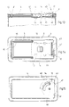
- the open end face is closed by a cover 4 which has a linearly guided slide 12.
- the slide 12 is part of the cover 4 and forms the closure for a removal opening 71.
- the detents locks 17 are arranged so that they can only be operated with two fingers of one hand at the same time.
- a handle 14 in the form of a gripping surface which, in the closed position, engages flush in a corresponding recess 70 on the cover 4.
- the lid 4 in turn has an annular flange 8, by means of which it is placed on the open end face of the container body 2 and permanently attached to it. As can be seen from FIGS. 23 and 24, it has two circumferential guide rails 20, one above the other, between which the slide 12 is guided.
- the guide strips 20 are designed somewhat wider on one side of the container, where the gripping surface 70 is also located.
- the locks 17 are also effective in this area.
- the locks 17 are each formed by a cam 18 on the cover 4 and an approximately contoured opening 19 on the slide 12.
- the cams 18 are arranged on the lower guide bar 20 of the cover 4 and, furthermore, a further opening 73 is arranged in alignment with the cam 18 on the upper guide bar, into which the cam engages in the closed position as well as in FIG Opening 19 on the slide 12.
- the cam 18 is seated on a resilient tongue 72, which is punched out, for example, of the lower guide bar 20 so that it has material connection to the guide bar only on one side.
- the cam 18 In the closed position, which is shown in solid lines in FIG. 24, the cam 18 extends through the opening 19 in the slide 12 and also engages in the opening 73 on the upper guide bar 20.
- the cams 18 of both locks 17 To open, the cams 18 of both locks 17 must be pressed down simultaneously with the fingers of one hand, the cams 18 deflecting downward due to the spring properties of the tongues 72. The pressure must be applied so that the cams disengage from the openings 19 and 73 so that the slider 12 can be pulled by a finger of the other hand on the gripping surface.
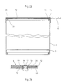
- FIGS. 25 to 28 Removal of the filling material, for example shown by pouring.
- a lid 4 is placed on the container body 2, which has a smaller removal opening 71 and a cover disk 74 which closes the remaining cross section.
- the slide 12 can be brought from the closed position shown in FIGS. 25 and 26 into an open position in which it lies largely above the cover plate 74 and opens the opening 71.
- the cover 4 has guide strips 20 above the cover disc 74 on opposite longitudinal sides, so that the slide 12 is guided between these guide strips and the cover disc 74.
- the slide 12 has a handle 14 in the form of a grip tab.
- the locks 17 are designed in the same way as in FIGS. 21 to 24. They are formed by cams 18 on the edge flange 8 and openings 19 in the slide 12. The cams 18 are in turn seated on resilient tongues 72, which in this case have been worked out of the cover disk 74. As in the exemplary embodiment described above, the two cams 18 and the openings 19 are arranged next to one another, for example on a line running perpendicular to the direction of movement.
- the slide 12 again has two openings 19 which are arranged and designed in the same way as in FIG. 26.
- the cams 18 are arranged differently. In the closed position, the cam 18 'engages in the opening 19, while the cam 18 "is ineffective below the slide 12.
- the removal opening 71 is made somewhat smaller by the right edge 75 being displaced further inward. About the removal opening To expose 71, the cam 18 'must first be pressed and the slide 12 must be moved in the opening direction with the other hand by gripping the handle 14. With this displacement, the slide reaches an intermediate position in which the cam 18 ⁇ , the tongue 72 ⁇ of the tongue 72 'of the other cam 18' opposite is engaged in the opening 19.
- the removal opening has not yet been opened in this intermediate position.
- the second lock is also released so that the slide 12 can be moved into the open position.
- the cams 18 'and 18" can be pressed one after the other. Is the function of the opening mechanism recognized, but the user can also press the cam 18 'at the same time and engage with the other finger in the opposite opening 19, so that the cam 18 "can not even snap into this opening.
- the removal opening 71 and the cams 18 ′, 18 ′′ with their tongues 72 ′ and 72 ′′ are designed in the same way as in the exemplary embodiment according to FIG. 29.
- the opening assigned to the cam 18 ′′ is formed as an elongated hole 76, the length of which corresponds to the displacement between the closed position and the intermediate position of the slide 12.
- the cam 18 ′ In order to open the removal opening 71, the cam 18 ′ must at least first be pressed into the opening 19 so that the slide 12 can be moved into the intermediate position, in which the cam 18 "strikes the opposite end of the elongated hole 76. By subsequently pressing the cam 18 ", the slide 12 can then be moved into the open position. If the user has recognized the opening mechanism, he can press both cams 18 'and 18" simultaneously in the closed position and at least the pressure on the cam 18 "for as long Let it continue until slot 76 has passed this cam.
Landscapes
- Engineering & Computer Science (AREA)
- Mechanical Engineering (AREA)
- Closures For Containers (AREA)
Abstract
Claims (32)
- Récipient (1), en particulier pour des produits coulants destinés à la consommation, comprenant un corps (2) lequel présente sur sa face ouverte un bourrelet (7) replié vers l'intérieur, un couvercle (4) immobilisé sur celui-ci, une ouverture de prélèvement et un organe de fermeture sous la forme d'une coulisse (12) avec une manette (14), qui peut être amené d'une position d'ouverture dans une position de fermeture dans laquelle il est arrêté au moyen d'un organe de verrouillage (17) agissant comme verrouillage protège-enfants, caractérisé en ce que le couvercle (4) présente sur des côtés sensiblement opposés des taquets (10, 11) qui s'engagent sous le bourrelet (7) dont au moins un (11) fait partie de la coulisse (12) laquelle est guidée sur le couvercle et peut être déplacée, au moyen de la manette (14) accessible à la face supérieure du couvercle et après l'actionnement des éléments de verrouillage (18, 19) qui forment le verrouillage, entre la position de fermeture dans laquelle le couvercle est bloqué sur le corps (2) et l'organe d'arrêt (17) enclenché, et la position d'ouverture dans laquelle le couvercle peut être retiré en dégageant la totalité du côté ouvert du corps.
- Récipient selon la revendication 1, caractérisé en ce que la coulisse (12) est placée sur la face inférieure du couvercle (4) et qu'elle traverse ledit couvercle avec la manette (14) qui lui est solidaire.
- Récipient selon l'une des revendications 1 ou 2, caractérisé en ce qu'au moins le taquet (10) placé en face de la coulisse (12) et solidaire du couvercle (4) est conformé en taquet d'enclenchement élastique (50) qui s'engage sous le bourrelet (7) du corps (2).
- Récipient selon l'une des revendications 1 à 3, caractérisé en ce que le taquet (11) de la coulisse (12) est, lui aussi, conformé en taquet d'enclenchement élastique (51).
- Récipient selon la revendication 4, caractérisé en ce que les taquets d'enclenchement élastiques (50, 51) ne s'écartent de manière élastique que lors de la mise en place du couvercle (4) et se verrouillent derrière le bourrelet (7) sous l'effet de forces de traction agissant sur ledit couvercle.
- Récipient selon l'une des revendications 4 ou 5, caractérisé en ce que les taquets d'enclenchement élastiques (50, 51) sont conformés sur le couvercle (4) et respectivement sur la coulisse (12).
- Récipient selon l'une des revendications 1 à 6, caractérisé en ce que l'organe d'arrêt (17) comprend au moins deux éléments de verrouillage (18, 19) disposés à distance l'un de l'autre mais à portée des doigts d'une seule main, qui agissent dans la position de fermeture de la coulisse (12) et qui, pour l'ouverture de ladite coulisse, ne peuvent être débloqués simultanément qu'au moyen d'au moins deux doigts.
- Récipient selon la revendication 7, caractérisé en ce que les deux éléments de verrouillage (18, 19) sont disposés l'un à côté de l'autre sur une ligne perpendiculaire à la direction de mouvement de la coulisse (12).
- Récipient selon la revendication 7, caractérisé en ce que les deux éléments de verrouillage (18, 19) sont décalés ou alignés l'un derrière l'autre dans la direction de mouvement de la coulisse (12).
- Récipient selon l'une des revendications 1 à 6, caractérisé en ce que l'organe d'arrêt (17) comprend au moins deux éléments de verrouillage (18, 19) disposés à distance l'un de l'autre et pouvant être débloqués avec les doigts, dont l'un agit dans la position de fermeture de la coulisse (12) et dont l'autre est disposé de manière qu'il se bloque dans une position intermédiaire de la coulisse (12) dans laquelle l'ouverture de prélèvement (71) est encore fermée et qu'il peut être débloqué dans la position intermédiaire à l'aide des doigts.
- Récipient selon la revendication 10, caractérisé en ce que les deux éléments de verrouillage (18, 19) agissent successivement dans la direction de mouvement de la coulisse (12).
- Récipient selon la revendication 10, caractérisé en ce que les deux éléments de verrouillage (18, 19) sont disposés et conformés de telle façon que l'un des éléments de verrouillage n'est activé que dans la position de fermeture et que l'autre intervient, dans la direction de mouvement de la coulisse (12), entre la position de fermeture et la position intermédiaire.
- Récipient selon l'une des revendications 1 à 12, caractérisé en ce que les éléments de verrouillage sont constitués par des ouvertures (19) ménagées dans la coulisse (12) ou dans le couvercle (4) et par des saillies (18) qui présentent sensiblement le même contour, s'enclenchent élastiquement dans lesdites ouvertures et servent d'organes de manoeuvre.
- Récipient selon l'une des revendications 1 à 13, caractérisé en ce que les organes de manoeuvre (18) sont prévus sur des languettes (72) élastiques.
- Récipient selon l'une des revendications 1 à 14, caractérisé en ce qu'au moins l'un des éléments de verrouillage (18, 19) constitue en même temps l'organe d'arrêt pour la coulisse (12) dans la position de fermeture.
- Récipient selon l'une des revendications 10 à 15, caractérisé en ce que, dans la position de fermeture de la coulisse (12), un organe de manoeuvre (18′) s'engage dans une ouverture (19) dans la coulisse (12), tandis que le second organe de manoeuvre (18") et la seconde ouverture sont séparés et ne viennent en prise que dans la position intermédiaire.
- Récipient selon l'une des revendications 13 à 15, caractérisé en ce que l'une des ouvertures (19) présente le même contour que l'organe de manoeuvre (18′), tandis que l'autre est conformée en trou oblong (76) qui s'étend, dans la direction de déplacement de la coulisse (12), entre la position de fermeture et la position intermédiaire.
- Récipient selon l'une des revendications 1 à 17, caractérisé en ce que l'organe d'arrêt (17) est constitué par au moins une saillie (33) montée élastiquement sur le couvercle (4) et par une surface d'arrêt (34) sur la coulisse (12) qui coopère avec ladite saillie, et que la saillie forme en même temps l'organe de manoeuvre pour l'organe d'arrêt.
- Récipient selon l'une des revendications 1 à 17, caractérisé en ce que l'organe d'arrêt (17) est constitué par au moins une baguette dentée (22, 24) disposée à la face inférieure du couvercle (4) et par une baguette dentée (26) correspondante montée de manière élastique sur la coulisse (12), cette dernière baguette dentée pouvant être désengrenée au moyen d'un organe de manoeuvre (18) contre l'action du ressort.
- Récipient selon la revendication 19, caractérisé en ce que la baguette dentée (24) sur le couvercle (4) se situe dans un plan parallèle à la surface du couvercle, et que l'organe de manoeuvre pour l'autre baguette dentée (26) sur la coulisse (12) forme en même temps la manette (27) de celle-ci.
- Récipient selon la revendication 19, caractérisé en ce que la baguette dentée (22) sur le couvercle (4) se situe dans un plan perpendiculaire à la surface du couvercle.
- Récipient selon l'une des revendications 19 ou 21, caractérisé en ce que deux baguettes dentées (22) sont prévues à distance l'une de l'autre, les dentures étant dirigées l'une vers l'autre, et que sur la coulisse (12) sont prévues deux baguettes dentées avec des dentures opposées qui, sous l'effet de ressort, sont déplacées vers l'extérieur dans les baguettes dentées (22) sur le couvercle (4) et séparées au moyen de deux organes de manoeuvre (18) devant être poussés l'un contre l'autre à l'aide d'une seule main.
- Récipient selon l'une des revendications 1 à 22, caractérisé en ce que la coulisse (12) est maintenue dans la position de fermeture au moyen d'un ressort (56) qui est réalisé sous la forme d'un support élastique soumis au flambage (36) avec position de point mort dans laquelle la coulisse (12) est maintenue dans la position de fermeture, et que le support soumis au flambage (36) sert en même temps d'organe d'arrêt étant donné que le point d'inflexion (39) du support soumis au flambage constitue l'organe de manoeuvre de l'organe d'arrêt et peut être amené par pression au-delà de la position de point mort dans une position instable dans laquelle la coulisse (12) peut être déplacée au moyen de la manette (14).
- Récipient selon l'une des revendications 1 à 23, caractérisé en ce que deux coulisses (12, 29) sont munies chacune d'une manette (14, 31) auxquelles est respectivement associé un organe d'arrêt (17).
- Récipient selon l'une des revendications 1 à 24, caractérisé en ce que la poignée de transport (5) forme en même temps une partie de l'organe d'arrêt (17) pour la coulisse (12) et que ledit organe d'arrêt peut être débloqué au moyen d'un mouvement pivotant de la poignée de transport.
- Récipient selon la revendication 25, caractérisé en ce que l'organe d'arrêt (17) comprend une saillie (42) montée de manière élastique sur le couvercle (4) ou sur la coulisse (12), qui s'engage dans un logement (43) ouvert vers le haut prévu sur le couvercle (4), et qu'une section (44) de la poignée de transport (5) peut être insérée par pivotement dans le logement (43) en repoussant la saillie (42).
- Récipient selon l'une des revendications 25 ou 26, caractérisé en ce que la poignée de transport (5) présente une section transversale en forme de bande, et que le logement (43) est conformé en fente correspondante.
- Récipient selon l'une des revendications 1 à 27, caractérisé en ce que l'organe d'arrêt (17) est relié au couvercle (4) ou à la coulisse (12) par l'intermédiaire d'une articulation et moulé par injection d'un seul tenant avec ceux-ci.
- Récipient selon l'une des revendications 1 à 28, caractérisé en ce que le couvercle (4) du récipient (1) forme avec la coulisse (12) un élément homogène qui peut être monté ultérieurement sur le corps (2) du récipient.
- Récipient selon l'une des revendications 1 à 29, caractérisé en ce que le couvercle (4) comporte au moins sur deux côtés opposés des surfaces de guidage (20) superposées entre lesquelles peut être déplacée la coulisse (12).
- Récipient selon l'une des revendications 1 à 30, caractérisé en ce que le couvercle (4) comporte une bride annulaire (8) qui peut être raccordée au corps (2) du récipient, et un disque de couvercle (74) qui recouvre la section transversale libre du corps (2) du récipient, exception faite de l'ouverture de prélèvement (71), que la coulisse (12) se trouve, dans la position d'ouverture, sensiblement au-dessus de ladite paroi, et que ladite paroi comporte les languettes (72) avec les organes de manoeuvre (18).
- Récipient selon l'une des revendications 1 à 31, caractérisé en ce que le couvercle (4) est conformé sensiblement en bride annulaire (8) munie de deux baguettes de guidage (20) qui dépassent dans la section transversale libre du corps (2) du récipient et forment des surfaces de guidage pour la coulisse (12), et que l'une des baguettes de guidage inférieures porte les languettes (72) avec les organes de manoeuvre (18), tandis que dans la baguette de guidage supérieure disposée au-dessus sont ménagées des ouvertures (73) correspondantes qui s'alignent avec les ouvertures (19) prévues dans la coulisse (12), dans la position de fermeture de ladite coulisse, et sont traversées, comme celles-ci, par les organes de manoeuvre (18).
Priority Applications (1)
| Application Number | Priority Date | Filing Date | Title |
|---|---|---|---|
| AT90910681T ATE83730T1 (de) | 1989-06-23 | 1990-06-23 | Behaelter fuer insbesondere rieselfaehige produkte. |
Applications Claiming Priority (4)
| Application Number | Priority Date | Filing Date | Title |
|---|---|---|---|
| DE8907662U DE8907662U1 (de) | 1989-06-23 | 1989-06-23 | Verpackungsbehälter |
| DE8907662U | 1989-06-23 | ||
| DE4015602 | 1990-05-15 | ||
| DE19904015602 DE4015602A1 (de) | 1990-05-15 | 1990-05-15 | Behaelter fuer rieselfaehige produkte, insbesondere haushaltsgrosspackung fuer waschmittel |
Publications (2)
| Publication Number | Publication Date |
|---|---|
| EP0478687A1 EP0478687A1 (fr) | 1992-04-08 |
| EP0478687B1 true EP0478687B1 (fr) | 1992-12-23 |
Family
ID=25893233
Family Applications (1)
| Application Number | Title | Priority Date | Filing Date |
|---|---|---|---|
| EP90910681A Expired - Lifetime EP0478687B1 (fr) | 1989-06-23 | 1990-06-23 | Recipient, notamment pour produits coulants |
Country Status (4)
| Country | Link |
|---|---|
| EP (1) | EP0478687B1 (fr) |
| AU (1) | AU5958990A (fr) |
| DE (1) | DE59000665D1 (fr) |
| WO (1) | WO1991000225A1 (fr) |
Cited By (1)
| Publication number | Priority date | Publication date | Assignee | Title |
|---|---|---|---|---|
| DE102019006379A1 (de) * | 2019-06-19 | 2020-12-24 | Brohl Wellpappe Gmbh & Co. Kg | Verpackung mit einer Fläche mit einem Zugang zum Verpackungsinneren |
Families Citing this family (6)
| Publication number | Priority date | Publication date | Assignee | Title |
|---|---|---|---|---|
| WO1992021583A1 (fr) * | 1991-05-27 | 1992-12-10 | Henkel Kommanditgesellschaft Auf Aktien | Fermeture avec couvercle mobile pour une boite pliante |
| FR2706423B1 (fr) * | 1993-06-09 | 1995-09-08 | Neuvibox | Couvercle de sécurité et contenant pourvu d'un tel couvercle. |
| DE9401206U1 (de) * | 1994-01-25 | 1995-05-24 | Joh. A. Benckiser Gmbh, 67059 Ludwigshafen | Deckel für einen Behälter |
| JP4609970B2 (ja) * | 2001-01-17 | 2011-01-12 | カシオ計算機株式会社 | 液晶表示装置 |
| PL2945876T3 (pl) * | 2013-01-16 | 2018-03-30 | Henkel Ag & Co. Kgaa | Pojemnik z urządzeniem zamykającym |
| US20180334297A1 (en) * | 2017-05-16 | 2018-11-22 | The Procter & Gamble Company | Container systems |
Citations (1)
| Publication number | Priority date | Publication date | Assignee | Title |
|---|---|---|---|---|
| DE3643600A1 (de) * | 1986-12-19 | 1988-07-07 | Henkel Kgaa | Deckel eines trommelfoermigen grossbehaelters |
Family Cites Families (5)
| Publication number | Priority date | Publication date | Assignee | Title |
|---|---|---|---|---|
| US2564252A (en) * | 1949-06-14 | 1951-08-14 | Jr Archie L Dickson | Box cap |
| FR1143524A (fr) * | 1953-09-25 | 1957-10-02 | Matiere Plastique | Boîte pour produits secs à l'état de division, par exemple en poudre ou en grains |
| US3240373A (en) * | 1964-10-26 | 1966-03-15 | Harold J Dulle | Safety closure for bottles |
| US4561544A (en) * | 1983-12-28 | 1985-12-31 | Calmar, Inc. | Child resistant container |
| US4520921A (en) * | 1984-03-23 | 1985-06-04 | Vissing Ellin D | Method and apparatus for closing cylindrical containers |
-
1990
- 1990-06-23 DE DE9090910681T patent/DE59000665D1/de not_active Expired - Fee Related
- 1990-06-23 WO PCT/EP1990/001001 patent/WO1991000225A1/fr not_active Ceased
- 1990-06-23 AU AU59589/90A patent/AU5958990A/en not_active Abandoned
- 1990-06-23 EP EP90910681A patent/EP0478687B1/fr not_active Expired - Lifetime
Patent Citations (1)
| Publication number | Priority date | Publication date | Assignee | Title |
|---|---|---|---|---|
| DE3643600A1 (de) * | 1986-12-19 | 1988-07-07 | Henkel Kgaa | Deckel eines trommelfoermigen grossbehaelters |
Cited By (1)
| Publication number | Priority date | Publication date | Assignee | Title |
|---|---|---|---|---|
| DE102019006379A1 (de) * | 2019-06-19 | 2020-12-24 | Brohl Wellpappe Gmbh & Co. Kg | Verpackung mit einer Fläche mit einem Zugang zum Verpackungsinneren |
Also Published As
| Publication number | Publication date |
|---|---|
| EP0478687A1 (fr) | 1992-04-08 |
| WO1991000225A1 (fr) | 1991-01-10 |
| AU5958990A (en) | 1991-01-17 |
| DE59000665D1 (de) | 1993-02-04 |
Similar Documents
| Publication | Publication Date | Title |
|---|---|---|
| DE69509099T2 (de) | Kindersicherer flaschnenverschluss | |
| DE69319442T2 (de) | Kindergesicherter verschluss mit versenkt eingebauter verriegelung | |
| EP0199900B1 (fr) | Distributeur de tablettes | |
| DE69809537T2 (de) | Betätigungsvorrichtung für eine sprühdose mit verbesserter befestigungsvorrichtung | |
| DE69409846T2 (de) | Kinder Sicherheitsverschluss | |
| DE69311544T2 (de) | Behälter und Verschluss | |
| DE3220346A1 (de) | Einwegbehaelter | |
| DE3801724A1 (de) | Kosmetikdose | |
| DE3006622A1 (de) | Kindern widerstehender bzw. kindersicherer behaelter und sicherheitsverschluss hierfuer | |
| DE2912381A1 (de) | Schneidgeraet | |
| EP0478687B1 (fr) | Recipient, notamment pour produits coulants | |
| EP1275591A2 (fr) | Distributeur de fluides | |
| DE7810971U1 (de) | Betaetigungsvorrichtung fuer Druckbehaelter | |
| DE2312939C3 (de) | Kindersichere Schutzkappe für in der Hand zu haltende Verteiler für Aerosol o.dgl | |
| DE3210361C2 (fr) | ||
| DE8535205U1 (de) | Verschluß | |
| DE8907662U1 (de) | Verpackungsbehälter | |
| EP0868360A1 (fr) | Capuchon de fermeture | |
| EP0087088B1 (fr) | Sangle porteuse pour récipients pourvus d'un couvercle | |
| DE68908721T2 (de) | Kindsicherer verschluss für eine flasche oder ähnliche behälter. | |
| EP3997004B1 (fr) | Récipient avec couvercle verrouillable | |
| EP0232550B1 (fr) | Récipient portable à fermeture inviolable par les enfants | |
| DE4015602A1 (de) | Behaelter fuer rieselfaehige produkte, insbesondere haushaltsgrosspackung fuer waschmittel | |
| DE3104604A1 (de) | Dosenverschluss | |
| DE3300190A1 (de) | Verschluss fuer behaelter mit verschliessbarem entnahmeroehrchen |
Legal Events
| Date | Code | Title | Description |
|---|---|---|---|
| PUAI | Public reference made under article 153(3) epc to a published international application that has entered the european phase |
Free format text: ORIGINAL CODE: 0009012 |
|
| 17P | Request for examination filed |
Effective date: 19911101 |
|
| AK | Designated contracting states |
Kind code of ref document: A1 Designated state(s): AT BE CH DE DK ES FR GB IT LI LU NL SE |
|
| 17Q | First examination report despatched |
Effective date: 19920610 |
|
| GRAA | (expected) grant |
Free format text: ORIGINAL CODE: 0009210 |
|
| AK | Designated contracting states |
Kind code of ref document: B1 Designated state(s): AT BE CH DE DK ES FR GB IT LI LU NL SE |
|
| PG25 | Lapsed in a contracting state [announced via postgrant information from national office to epo] |
Ref country code: SE Effective date: 19921223 Ref country code: ES Free format text: THE PATENT HAS BEEN ANNULLED BY A DECISION OF A NATIONAL AUTHORITY Effective date: 19921223 Ref country code: DK Effective date: 19921223 |
|
| REF | Corresponds to: |
Ref document number: 83730 Country of ref document: AT Date of ref document: 19930115 Kind code of ref document: T |
|
| REF | Corresponds to: |
Ref document number: 59000665 Country of ref document: DE Date of ref document: 19930204 |
|
| ET | Fr: translation filed | ||
| ITF | It: translation for a ep patent filed | ||
| GBT | Gb: translation of ep patent filed (gb section 77(6)(a)/1977) |
Effective date: 19930225 |
|
| PG25 | Lapsed in a contracting state [announced via postgrant information from national office to epo] |
Ref country code: AT Effective date: 19930623 |
|
| PG25 | Lapsed in a contracting state [announced via postgrant information from national office to epo] |
Ref country code: LU Free format text: LAPSE BECAUSE OF NON-PAYMENT OF DUE FEES Effective date: 19930630 |
|
| PLBE | No opposition filed within time limit |
Free format text: ORIGINAL CODE: 0009261 |
|
| STAA | Information on the status of an ep patent application or granted ep patent |
Free format text: STATUS: NO OPPOSITION FILED WITHIN TIME LIMIT |
|
| 26N | No opposition filed | ||
| PGFP | Annual fee paid to national office [announced via postgrant information from national office to epo] |
Ref country code: CH Payment date: 19950830 Year of fee payment: 6 |
|
| PGFP | Annual fee paid to national office [announced via postgrant information from national office to epo] |
Ref country code: BE Payment date: 19960603 Year of fee payment: 7 |
|
| PGFP | Annual fee paid to national office [announced via postgrant information from national office to epo] |
Ref country code: GB Payment date: 19960611 Year of fee payment: 7 Ref country code: FR Payment date: 19960611 Year of fee payment: 7 |
|
| PG25 | Lapsed in a contracting state [announced via postgrant information from national office to epo] |
Ref country code: LI Effective date: 19960630 Ref country code: CH Effective date: 19960630 |
|
| PGFP | Annual fee paid to national office [announced via postgrant information from national office to epo] |
Ref country code: NL Payment date: 19960630 Year of fee payment: 7 |
|
| PGFP | Annual fee paid to national office [announced via postgrant information from national office to epo] |
Ref country code: DE Payment date: 19960718 Year of fee payment: 7 |
|
| REG | Reference to a national code |
Ref country code: CH Ref legal event code: PL |
|
| PG25 | Lapsed in a contracting state [announced via postgrant information from national office to epo] |
Ref country code: GB Free format text: LAPSE BECAUSE OF NON-PAYMENT OF DUE FEES Effective date: 19970623 |
|
| PG25 | Lapsed in a contracting state [announced via postgrant information from national office to epo] |
Ref country code: BE Effective date: 19970630 |
|
| BERE | Be: lapsed |
Owner name: WEIDENHAMMER PACKUNGEN K.G. G.M.B.H. & CO. Effective date: 19970630 |
|
| PG25 | Lapsed in a contracting state [announced via postgrant information from national office to epo] |
Ref country code: NL Effective date: 19980101 |
|
| GBPC | Gb: european patent ceased through non-payment of renewal fee |
Effective date: 19970623 |
|
| PG25 | Lapsed in a contracting state [announced via postgrant information from national office to epo] |
Ref country code: FR Free format text: LAPSE BECAUSE OF NON-PAYMENT OF DUE FEES Effective date: 19980227 |
|
| NLV4 | Nl: lapsed or anulled due to non-payment of the annual fee |
Effective date: 19980101 |
|
| PG25 | Lapsed in a contracting state [announced via postgrant information from national office to epo] |
Ref country code: DE Free format text: LAPSE BECAUSE OF NON-PAYMENT OF DUE FEES Effective date: 19980303 |
|
| REG | Reference to a national code |
Ref country code: FR Ref legal event code: ST |
|
| REG | Reference to a national code |
Ref country code: FR Ref legal event code: ST |
|
| PG25 | Lapsed in a contracting state [announced via postgrant information from national office to epo] |
Ref country code: IT Free format text: LAPSE BECAUSE OF NON-PAYMENT OF DUE FEES;WARNING: LAPSES OF ITALIAN PATENTS WITH EFFECTIVE DATE BEFORE 2007 MAY HAVE OCCURRED AT ANY TIME BEFORE 2007. THE CORRECT EFFECTIVE DATE MAY BE DIFFERENT FROM THE ONE RECORDED. Effective date: 20050623 |