EP0478917B1 - Dispositif de rattrapage automatique de jeu pour un frein à disque à étrier flottant à commande mécanique - Google Patents
Dispositif de rattrapage automatique de jeu pour un frein à disque à étrier flottant à commande mécanique Download PDFInfo
- Publication number
- EP0478917B1 EP0478917B1 EP91112627A EP91112627A EP0478917B1 EP 0478917 B1 EP0478917 B1 EP 0478917B1 EP 91112627 A EP91112627 A EP 91112627A EP 91112627 A EP91112627 A EP 91112627A EP 0478917 B1 EP0478917 B1 EP 0478917B1
- Authority
- EP
- European Patent Office
- Prior art keywords
- adjusting
- sleeve
- ring
- brake
- extension
- Prior art date
- Legal status (The legal status is an assumption and is not a legal conclusion. Google has not performed a legal analysis and makes no representation as to the accuracy of the status listed.)
- Expired - Lifetime
Links
- 238000006073 displacement reaction Methods 0.000 claims description 3
- 238000010276 construction Methods 0.000 claims 1
- 230000006835 compression Effects 0.000 description 14
- 238000007906 compression Methods 0.000 description 14
- 230000003068 static effect Effects 0.000 description 8
- 230000008878 coupling Effects 0.000 description 5
- 238000010168 coupling process Methods 0.000 description 5
- 238000005859 coupling reaction Methods 0.000 description 5
- 230000001419 dependent effect Effects 0.000 description 4
- 238000000034 method Methods 0.000 description 3
- 230000008569 process Effects 0.000 description 3
- 230000009467 reduction Effects 0.000 description 3
- 230000005540 biological transmission Effects 0.000 description 2
- 238000011161 development Methods 0.000 description 2
- 230000018109 developmental process Effects 0.000 description 2
- 238000009434 installation Methods 0.000 description 2
- 238000004519 manufacturing process Methods 0.000 description 2
- 230000007246 mechanism Effects 0.000 description 2
- 230000036316 preload Effects 0.000 description 2
- 230000009471 action Effects 0.000 description 1
- 230000000694 effects Effects 0.000 description 1
- 230000005489 elastic deformation Effects 0.000 description 1
- 230000009191 jumping Effects 0.000 description 1
- 230000002093 peripheral effect Effects 0.000 description 1
- 230000035939 shock Effects 0.000 description 1
- 230000007480 spreading Effects 0.000 description 1
- 230000008961 swelling Effects 0.000 description 1
Images

Classifications
-
- F—MECHANICAL ENGINEERING; LIGHTING; HEATING; WEAPONS; BLASTING
- F16—ENGINEERING ELEMENTS AND UNITS; GENERAL MEASURES FOR PRODUCING AND MAINTAINING EFFECTIVE FUNCTIONING OF MACHINES OR INSTALLATIONS; THERMAL INSULATION IN GENERAL
- F16D—COUPLINGS FOR TRANSMITTING ROTATION; CLUTCHES; BRAKES
- F16D65/00—Parts or details
- F16D65/38—Slack adjusters
- F16D65/40—Slack adjusters mechanical
- F16D65/52—Slack adjusters mechanical self-acting in one direction for adjusting excessive play
- F16D65/56—Slack adjusters mechanical self-acting in one direction for adjusting excessive play with screw-thread and nut
- F16D65/567—Slack adjusters mechanical self-acting in one direction for adjusting excessive play with screw-thread and nut for mounting on a disc brake
-
- F—MECHANICAL ENGINEERING; LIGHTING; HEATING; WEAPONS; BLASTING
- F16—ENGINEERING ELEMENTS AND UNITS; GENERAL MEASURES FOR PRODUCING AND MAINTAINING EFFECTIVE FUNCTIONING OF MACHINES OR INSTALLATIONS; THERMAL INSULATION IN GENERAL
- F16D—COUPLINGS FOR TRANSMITTING ROTATION; CLUTCHES; BRAKES
- F16D2121/00—Type of actuator operation force
- F16D2121/02—Fluid pressure
-
- F—MECHANICAL ENGINEERING; LIGHTING; HEATING; WEAPONS; BLASTING
- F16—ENGINEERING ELEMENTS AND UNITS; GENERAL MEASURES FOR PRODUCING AND MAINTAINING EFFECTIVE FUNCTIONING OF MACHINES OR INSTALLATIONS; THERMAL INSULATION IN GENERAL
- F16D—COUPLINGS FOR TRANSMITTING ROTATION; CLUTCHES; BRAKES
- F16D2121/00—Type of actuator operation force
- F16D2121/14—Mechanical
-
- F—MECHANICAL ENGINEERING; LIGHTING; HEATING; WEAPONS; BLASTING
- F16—ENGINEERING ELEMENTS AND UNITS; GENERAL MEASURES FOR PRODUCING AND MAINTAINING EFFECTIVE FUNCTIONING OF MACHINES OR INSTALLATIONS; THERMAL INSULATION IN GENERAL
- F16D—COUPLINGS FOR TRANSMITTING ROTATION; CLUTCHES; BRAKES
- F16D2123/00—Multiple operation forces
-
- F—MECHANICAL ENGINEERING; LIGHTING; HEATING; WEAPONS; BLASTING
- F16—ENGINEERING ELEMENTS AND UNITS; GENERAL MEASURES FOR PRODUCING AND MAINTAINING EFFECTIVE FUNCTIONING OF MACHINES OR INSTALLATIONS; THERMAL INSULATION IN GENERAL
- F16D—COUPLINGS FOR TRANSMITTING ROTATION; CLUTCHES; BRAKES
- F16D2125/00—Components of actuators
- F16D2125/18—Mechanical mechanisms
- F16D2125/20—Mechanical mechanisms converting rotation to linear movement or vice versa
- F16D2125/34—Mechanical mechanisms converting rotation to linear movement or vice versa acting in the direction of the axis of rotation
- F16D2125/36—Helical cams, Ball-rotating ramps
Definitions
- the invention relates to an automatic adjusting device for a mechanically actuated disc brake with a sliding caliper which is mounted transversely to the brake disc and which overlaps the brake disc with its two halves of the caliper, each having a brake pad carrier with a brake lining, with an actuating shaft which is rotatably mounted in a caliper half and which terminates on its sleeve-shaped End has a radially projecting collar, which is provided on one side with angular raceways for receiving balls, which correspond to angular raceways on a bearing ring and serve to convert the rotary movement of the actuating shaft into an axial movement of a pressure screw connected to the piston in a rotationally fixed manner, whereby the actuating shaft is secured against axial displacement on that side of the federal government which faces away from the diagonal raceways, via an axial bearing on the sliding calliper, the bearing ring in relation to the brake calliper a xial displaceable, but against Rotation is secured and is supported on a
- An adjustment device of this type described in DE-OS 38 14 475 gradually adjusts for wear of the brake pads by means of an axially displaceable sawtooth ratchet.
- the clearance is thus determined by the selected tooth pitch. A reduction in the clearance due to a very small tooth pitch is not possible for manufacturing reasons.
- a correspondingly large actuation stroke (idle stroke) of the brake actuation is therefore required to overcome the clearance, which can also result in a reduction in the reserve of the actuation path.
- the size of the actuation stroke is also determined by the inclination of the inclined raceways on the bearing ring and on the actuation shaft. A small slope requires a relatively large actuation stroke for the spread. An increase in the slope, the faster Installation of the brake shoes on the brake disc with a reduction in the actuation stroke results in larger actuation cylinders due to smaller ratios in order to achieve the same braking effect.
- the adjustment device according to the invention is intended to achieve a significant simplification compared to the prior art and to reduce the number of adjustment parts required.
- the adjustment device according to the invention should also enable easier resetting, on the one hand avoiding chatter phenomena when the helical gear is skipped quickly, and on the other hand bypassing the use of a tolerance ring which acts as a frictional clutch and which makes resetting difficult due to fluctuations in the coefficient of friction.
- this object is achieved in that the adjusting sleeve is rotatably mounted on the extension piece of the adjusting nut and is supported on a collar thereof, that the spring component is supported on the adjusting ring, that the adjusting sleeve is connected to the adjusting nut via an adjusting coupling, in that the Adjuster ring or in the Actuating shaft formed groove is an axial groove and that the helical gears arranged on the end faces of the adjusting sleeve and the adjusting ring in the brake actuation direction with mutual compression allow the spring component to jump over.
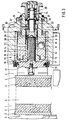
- the sliding caliper disc brake illustrated comprises a sliding caliper 1 which overlaps the brake disc 6 indicated by dash-dotted lines with its two caliper halves 4 and 5.
- the two halves of the saddle each have a brake pad carrier 2, which carries a brake pad 3 facing the brake disk 6.
- an actuating shaft 7 is rotatably mounted via a lever (not shown).
- This actuating shaft 7 ends in a sleeve-shaped end with a radially projecting collar 9.
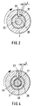
- This covenant 9 is provided on its side facing away from the lever with at least two, preferably three inclined raceways 10 for receiving balls 11, which on the other hand run in corresponding oblique raceways 12 on a bearing ring 13.
- the mutually corresponding inclined raceways 10 and 12 are arranged in relation to one another on the collar 9 or on the bearing ring 13 such that a rotation of the actuating shaft 7 is converted into an axial movement of the bearing ring 13 and an adjusting nut 14.
- a pressure screw 15 is screwed into this adjusting nut 14 and is connected in a rotationally fixed manner to a piston 21 which is secured against rotation.
- the latter is provided with a radially projecting shoulder 17 on which the bearing ring 13 is supported.
- a rotation lock in the form of an axially parallel guide groove 18 is provided, in which a guide pin 19 which also penetrates the piston 21 in a groove 22 engages .
- This guide pin 19 is formed by the front end of a screw bolt 20 screwed into a radial threaded bore of the sliding saddle 1.
- an axial bearing 27 is provided, via which the actuating shaft 7 is supported on the sliding caliper 1.
- the adjusting nut 14 is rotatably connected to an extension piece 24.
- An adjusting sleeve 28 and an adjusting ring 29 are rotatably arranged on the extension piece 24, the mutually facing end faces of which have helical teeth 30.
- the two adjustment parts 28 and 29 are through a compression spring 23 which is supported on the extension piece 24 is held in contact, since the adjusting sleeve 28 bears against the shoulder on the adjusting nut 14.
- the helical teeth 30 could also be replaced by a friction clutch.
- a friction clutch Preferably, however, a very small helical toothing is used, since friction clutches tend to unintentionally separate due to vibrations or shocks.
- the game L represents the release play. However, the play can also be omitted if the desired release play results solely from the manufacturing tolerances of the brake parts.
- a wrap spring 33 connecting these two parts is arranged on both sides of a collar on the circumferential surfaces of the adjusting nut 14 and the adjusting sleeve 28.
- This wrap spring 33 lies with its cylindrically wound spring body under radial prestress on the peripheral surfaces of the adjusting parts 14, 28 and forms a directional coupling.
- this directional clutch transmits a torque from the adjusting sleeve 28 to the adjusting nut 14, and when the brake is released, it slips like a freewheel.
- the downstream force-dependent clutch is produced by the helical gears 30 or otherwise by a friction clutch between the adjusting parts 28 and 29.
- the actuating shaft 7 If the actuating shaft 7 is moved in the direction of the arrow during the braking process, its pin 32 engages in the axial groove 31 of the adjusting ring 29 without play or with a play L as a result of the prestressing of the compression spring 23 via the helical gears 30 or via a friction clutch, the adjusting sleeve 28. This movement of the adjusting parts 28, 29 is immediately transmitted to the adjusting nut 14 by the wrap spring 33. The torque is greater than the friction torque between the shoulder 17 of the adjusting nut 14 and the bearing ring 13, which is established via the second compression spring 25. The clearance is adjusted by the rotation of the adjusting nut 14 with respect to the pressure screw 15.
- the biasing force of the compression spring 23 presses the adjusting parts 28, 29 against one another, and the pin 32 rotates these parts 28, 29 back as a result of the wear of the brake linings due to the release movement of the actuating shaft 7.
- the adjusting nut 14 is not rotated back because it is held in contact with the bearing ring 13 via the second compression spring 25 and because the wrap spring 33 also acts as a freewheel during the release movement.
- the release process which is necessary when replacing the brake pads and with a new basic setting, is extremely simple.
- the adjusting nut 14 is turned back in the locking direction of the wrap spring 33 by means of a key engaging on the extension piece 24, the teeth of the helical teeth 30 jumping over one another.
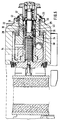
- the adjusting sleeve 28 is provided with an extension on which the adjusting ring 29 is rotatably and axially displaceable. This is acted upon by the compression spring 23, which in turn is supported on the extension piece 24 of the adjusting nut 14 via a washer on the locking ring 36. As a result, the helical toothing 30 of the force-dependent clutch is held in engagement.
- the adjusting sleeve 28 itself is positioned against axial displacement on the extension piece 24 of the adjusting nut 14 by a fixed stop 37.
- the adjusting sleeve 28 is thus fixed in its contact between the end face 38 of the adjusting nut 14 and the fixed stop 37 without spring preload, but with little play.
- the above-described undesirable axial static friction due to spring preload is thus eliminated between parts 14 and 28.
- the adjusting parts 28 and 29 can be rotated with the actuating shaft 7 in the freewheeling direction of the one-way clutch 33 without the adjustment nut 14 being undesirably taken along in this direction.
- the wrap spring 33 which acts as a directional coupling for torque transmission between the adjusting nut 14 and the adjusting sleeve 28, is omitted.
- a sleeve freewheel 34 which also serves as a directional coupling for torque transmission between the adjusting nut 14 and the adjusting sleeve 28.
- the outer ring 35 of the sleeve freewheel 34 sits on the inner circumference of the adjusting sleeve 28, and the The inner ring of the sleeve freewheel 34 is seated via its needle bearing on the outer circumference of the extension piece 24 of the adjusting nut 14.
- This embodiment also ensures that no static friction occurs between the adjusting sleeve 28 and the adjusting nut 14.
- the adjusting ring 29 is seated on a sleeve 39.
- This has two radially outwardly extending collars, one collar 40 engaging behind a radially inward collar of the adjusting sleeve 28 and the other collar 41 as a support for the compression spring 23 and serves as an attachment to the fixed stop 37.
- the adjusting parts 28 and 29 are clamped to one another, but no axial static friction occurs between the adjusting parts and the adjusting nut 14 via the compression spring 23.
Landscapes
- Engineering & Computer Science (AREA)
- General Engineering & Computer Science (AREA)
- Mechanical Engineering (AREA)
- Braking Arrangements (AREA)
Claims (7)
- Système automatique de rattrapage pour un frein à disque à commande mécanique comportant un étrier coulissant (1) installé perpendiculairement par rapport au disque de frein (6), et qui vient en prise, par ses deux demi-étriers (4-5) supportant chacun un support de garniture (2) et une garniture (3), avec le disque de frein (6),
un arbre de commande (7), monté rotatif dans un demi-étrier cet arbre portant à son extrémité, qui se prolonge en forme de douille, une collerette (9) qui, d'un côté, présente des chemins de roulement obliques (10) destinés à recevoir des billes (11) correspondant à d'autre chemins de roulement obliques (12) prévus sur un anneau formant palier (13), le tout réalisant la transformation du mouvement de rotation de l'arbre en un mouvement axial d'une vis de pression (15) solidaire de piston (21),
l'arbre de commande (7) étant assuré contre un déplacement axial sur le côté de sa collerette (9) qui est opposé à son chemin de roulement oblique (10), par un palier axial (27) porté par l'étrier,
l'anneau formant palier (13) étant mobile axialement par rapport à l'étrier mais étant assuré contre un mouvement de rotation, et étant en appui sur un écrou de rattrapage (14) en forme de douille, dans lequel la vis de pression (15) est vissée, et qui est fixé sans rotation possible à une rallonge (24) laquelle est contenue coaxialement dans l'arbre de commande (7) ;
un anneau de rattrapage (29) étant monté rotatif par rapport à la rallonge (24) de l'écrou de rattrapage (14),
l'anneau de rattrapage (29) ou l'arbre de commande (7) portant un tourillon radial (32) qui pénètre dans une rainure de l'arbre de commande (7) ou de l'anneau de rattrapage (29), et est associé à une gaine de rattrapage (28) se trouvant sur la rallonge (24),
l'anneau de rattrapage (29) et la gaine de rattrapage (28) portant en leurs parties frontales tournées l'une vers l'autre, des dentures obliques, l'une de ces deux pièces de rattrapage (28-29) portant des dentures obliques s'appuyant sur une collerette de l'écrou de rattrapage (14); une pièce à ressort (23) s'appuyant sur l'autre pièce de rattrapage pour maintenir les dentures obliques (30) en prise, avec un couplage de direction disposé dans le flux de force allant de l'anneau de rattrapage (29) vers l'écrou de rattrapage (14), ce couplage étant efficace dans le sens de commande du frein lors de la rotation de l'arbre de commande (7),
et un dispositif limiteur de couple qui limite le couple de rotation qui peut être transmis de l'anneau de rattrapage (29) à l'écrou de rattrapage (14),
caractérisé en ce que la gaine de rattrapage (28) est montée à rotation sur la rallonge (24) de l'écrou de rattrapage (14) et s'appuie sur une collerette de ce dernier ;
en ce que la pièce à ressort (23) s'appuie sur l'anneau de rattrapage (29),
en ce que la gaine de rattrapage (28) est liée à l'écrou de rattrapage (14) par le biais d'un accouplement de rattrapage (33-34),
en ce que la rainure (31) prévue dans l'anneau de rattrapage (29) ou l'arbre de commande (7) est une rainure axiale,
et en ce que les dentures obliques (30) prévues sur les faces frontales de la gaine (28) et de l'anneau (29) de rattrapage permettent un saut relatif dans la direction de la commande de freinage sous une compression de la pièce à ressort (23). - Dispositif de rattrapage selon la revendication 1, caractérisé en ce que l'accouplement de direction est produit par un ressort enroulé (33).
- Dispositif de rattrapage selon la revendication 1, caractérisé en ce que la direction d'accouplement sera produite par une roue libre de douille (34).
- Dispositif de rattrapage selon l'une des revendications 1 à 3, caractérisé en ce que l'anneau de réglage (29) est monté en rotation directement sur la rallonge (24) de l'écrou de rattrapage (14), et en ce que la pièce à ressort (23) s'appuie sur la rallonge (24) de l'écrou de rattrapage (14).
- Dispositif de rattrapage selon l'une des revendications 1 à 3, caractérisé en ce que la gaine de rattrapage est munie d'un prolongement positionné axialement par une butée (37) sur la rallonge (24) de l'écrou de réglage (14),
en ce que l'anneau de rattrapage (29) est monté à rotation et coulissement axial sur le prolongement de la gaine de réglage (28)
et en ce que la pièce à ressort (23) s'appuie sur une face frontale (36, 41) du prolongement de la gaine de rattrapage (28). - Dispositif de rattrapage selon la revendication 5, caractérisé en ce que le prolongement et la gaine de rattrapage (28) sont d'une seule pièce, et que la face frontale du prolongement est constituée d'un circlip (36).
- Dispositif de rattrapage selon la revendication 5, caractérisé en ce que le prolongement de la gaine de rattrapage (28) est constitué par une douille spéciale (39) qui prend par derrière la gaine de rattrapage (28) par une première collerette (40), et en ce que la partie frontale du prolongement est formée par une deuxième collerette (41) de la douille (39).
Applications Claiming Priority (2)
| Application Number | Priority Date | Filing Date | Title |
|---|---|---|---|
| DE4031616 | 1990-10-05 | ||
| DE4031616A DE4031616C2 (de) | 1990-10-05 | 1990-10-05 | Automatische Nachstelleinrichtung für eine mechanisch betätigte Gleitsattel-Scheibenbremse |
Publications (2)
| Publication Number | Publication Date |
|---|---|
| EP0478917A1 EP0478917A1 (fr) | 1992-04-08 |
| EP0478917B1 true EP0478917B1 (fr) | 1994-05-25 |
Family
ID=6415695
Family Applications (1)
| Application Number | Title | Priority Date | Filing Date |
|---|---|---|---|
| EP91112627A Expired - Lifetime EP0478917B1 (fr) | 1990-10-05 | 1991-07-26 | Dispositif de rattrapage automatique de jeu pour un frein à disque à étrier flottant à commande mécanique |
Country Status (3)
| Country | Link |
|---|---|
| US (1) | US5123505A (fr) |
| EP (1) | EP0478917B1 (fr) |
| DE (1) | DE4031616C2 (fr) |
Families Citing this family (34)
| Publication number | Priority date | Publication date | Assignee | Title |
|---|---|---|---|---|
| DE4307018A1 (de) * | 1993-03-05 | 1994-09-08 | Perrot Bremse Gmbh Deutsche | Nachstellvorrichtung für eine Scheibenbremse |
| DE4323292A1 (de) * | 1993-07-12 | 1995-01-19 | Perrot Bremse Gmbh Deutsche | Nachstellvorrichtung für eine Scheibenbremse |
| JP3104561B2 (ja) * | 1995-02-21 | 2000-10-30 | トヨタ自動車株式会社 | クラッチ装置 |
| DE19507308A1 (de) * | 1995-03-02 | 1996-09-05 | Perrot Bremsen Gmbh | Scheibenbremse |
| DE19515063C2 (de) * | 1995-04-27 | 2002-06-06 | Knorr Bremse Systeme | Scheibenbremse für Fahrzeuge, insbesondere Straßenfahrzeuge |
| SE508707C2 (sv) * | 1995-10-02 | 1998-10-26 | Volvo Ab | Anordning vid skivbromsar för motorfordon |
| DE19621533A1 (de) * | 1996-05-29 | 1997-12-04 | Bosch Gmbh Robert | Elektromotorische Bremsvorrichtung |
| US5722516A (en) * | 1996-11-12 | 1998-03-03 | Meritor Heavy Vehicle Systems, Llc | Disc brake with rigid connection between load plate and adjusting piston |
| US5794738A (en) * | 1996-11-12 | 1998-08-18 | Rockwell Heavy Vehicle Systems, Inc. | Disc brake with gear driven adjusting piston |
| DE19654729A1 (de) * | 1996-12-30 | 1999-07-22 | Bosch Gmbh Robert | Elektromotorische Bremsvorrichtung |
| DE19750273A1 (de) * | 1997-11-13 | 1999-05-20 | Bosch Gmbh Robert | Elektromechanische Bremse für Kraftfahrzeuge |
| DE19818157B4 (de) * | 1998-04-23 | 2012-05-16 | Robert Bosch Gmbh | Elektromechanische Radbremsvorrichtung |
| SE516495C2 (sv) | 2000-05-31 | 2002-01-22 | Haldex Brake Prod Ab | Bromsmekanism och bromsok för en skivbroms |
| SE522395C2 (sv) | 2000-05-31 | 2004-02-03 | Haldex Brake Prod Ab | Modulformad bromsmekanism |
| SE516513C2 (sv) | 2000-05-31 | 2002-01-22 | Haldex Brake Prod Ab | Skivbroms innefattande en bromsmekanism |
| SE522332C2 (sv) | 2000-05-31 | 2004-02-03 | Haldex Brake Prod Ab | Förfarande för att montera en bromsmekanism i ett bromsok samt ett sådant bromsok |
| JP4711562B2 (ja) * | 2001-08-29 | 2011-06-29 | 曙ブレーキ工業株式会社 | 電動式ブレーキ機構を備えたブレーキ装置 |
| JP4032386B2 (ja) * | 2002-11-29 | 2008-01-16 | 株式会社日立製作所 | 電動ディスクブレーキ |
| DE10262110B4 (de) * | 2002-12-23 | 2016-07-14 | Haldex Brake Products Ab | Bremsmechanismus für eine Scheibenbremse |
| AU2003292256A1 (en) * | 2002-12-23 | 2004-07-22 | Haldex Brake Products Ab | Brake gear for a disc brake |
| JP4546410B2 (ja) * | 2006-03-13 | 2010-09-15 | 日信工業株式会社 | 車両用ディスクブレーキ |
| DE102008005454B4 (de) * | 2008-01-22 | 2010-03-25 | Knorr-Bremse Systeme für Nutzfahrzeuge GmbH | Scheibenbremse mit Rutschkupplung für die Nachstelleinrichtung |
| DE102010008927B4 (de) * | 2010-02-23 | 2019-10-24 | Lucas Automotive Gmbh | Fahrzeugbremse mit Spindel/Mutter-Anordnung |
| DE102010011725A1 (de) * | 2010-03-17 | 2011-09-22 | Haldex Brake Products Ab | Scheibenbremse und Herstellungsverfahren für eine Scheibenbremse |
| DE102012014886A1 (de) * | 2012-07-26 | 2014-01-30 | Knorr-Bremse Systeme für Nutzfahrzeuge GmbH | Zuspanneinrichtung einer Scheibenbremse für ein Nutzfahrzeug |
| EP2865916B1 (fr) * | 2012-09-28 | 2016-10-19 | Honda Motor Co., Ltd. | Étrier de frein |
| JP6333020B2 (ja) * | 2014-03-31 | 2018-05-30 | 日信工業株式会社 | ディスクブレーキ装置 |
| US10066692B2 (en) * | 2014-04-04 | 2018-09-04 | Haldex Brake Products Ab | Brake actuation mechanism for a disc brake and disc brake comprising the same |
| DE102014017438A1 (de) * | 2014-11-25 | 2016-05-25 | Wabco Europe Bvba | Scheibenbremse. insbesondere für Nutzfahrzeuge |
| KR102167450B1 (ko) | 2019-03-14 | 2020-10-19 | 주식회사 만도 | 스티어 바이 와이어용 조향장치 |
| US11105386B2 (en) * | 2020-01-15 | 2021-08-31 | Chih-Hsien Liao | Brake caliper device having automatic pad wear compensation mechanism |
| DE102021203069A1 (de) * | 2020-04-03 | 2021-10-07 | Mando Corporation | Reibungsbremssystem für ein Fahrzeug |
| DE102021214437A1 (de) * | 2021-02-18 | 2022-08-18 | Mando Corporation | Reibungsbremssystem für ein Fahrzeug |
| IT202100012968A1 (it) * | 2021-05-19 | 2022-11-19 | Brembo Spa | Impianto frenante con freni a disco di tipo brake-by-wire, dotato di regolazione dinamica della distanza tra il disco freno e le pastiglie e relativo metodo di regolazione della distanza tra il disco freno e le pastiglie in un impianto frenante di tipo brake-by-wire |
Family Cites Families (6)
| Publication number | Priority date | Publication date | Assignee | Title |
|---|---|---|---|---|
| HU170699B (fr) * | 1974-01-31 | 1977-08-28 | ||
| BR8000881A (pt) * | 1979-02-14 | 1980-10-21 | Kelsey Hayes Co | Ajustador de folga,mecanismo de freio e acionador de freio de calibre |
| DE3445563A1 (de) * | 1984-12-14 | 1986-06-19 | Alfred Teves Gmbh, 6000 Frankfurt | Nachstellvorrichtung fuer eine scheibenbremse, insbesondere fuer kraftfahrzeuge |
| DE8633923U1 (de) * | 1986-12-18 | 1988-04-21 | Lucas Industries P.L.C., Birmingham, West Midlands | Betätigungsvorrichtung mit selbsttätiger Nachstellung für Bremsen, insbesondere von Schwerlastfahrzeugen |
| DE3814475A1 (de) * | 1988-04-28 | 1989-11-09 | Perrot Bremse Gmbh Deutsche | Mechanisch betaetigte gleitsattel-scheibenbremse |
| DE3841593A1 (de) * | 1988-04-28 | 1990-06-13 | Perrot Bremse Gmbh Deutsche | Mechanisch betaetigte gleitsattel-scheibenbremse |
-
1990
- 1990-10-05 DE DE4031616A patent/DE4031616C2/de not_active Expired - Fee Related
-
1991
- 1991-07-26 EP EP91112627A patent/EP0478917B1/fr not_active Expired - Lifetime
- 1991-10-07 US US07/772,658 patent/US5123505A/en not_active Expired - Fee Related
Also Published As
| Publication number | Publication date |
|---|---|
| US5123505A (en) | 1992-06-23 |
| EP0478917A1 (fr) | 1992-04-08 |
| DE4031616C2 (de) | 1999-11-25 |
| DE4031616A1 (de) | 1992-04-09 |
Similar Documents
| Publication | Publication Date | Title |
|---|---|---|
| EP0478917B1 (fr) | Dispositif de rattrapage automatique de jeu pour un frein à disque à étrier flottant à commande mécanique | |
| DE19729024C1 (de) | Verschleißnachstellvorrichtung für Scheibenbremsen | |
| EP2307756B1 (fr) | Dispositif de rattrapage de jeu pour un frein à disque | |
| DE2608502C3 (de) | Lösevorrichtung für die Unterbrechung und automatische Rückführung der Betriebsfunktion eines Federspeicherbremszylinders | |
| DE2408706A1 (de) | Betaetigungsvorrichtung fuer eine fahrzeug-bremsanlage mit selbsttaetiger spielnachstellvorrichtung | |
| DE3005420C2 (fr) | ||
| DE69724983T9 (de) | Scheibenbremse mit zahnradgetriebenem nachstellkolben | |
| DE19648581B4 (de) | Scheibenbremse mit Feststellbremsfunktion | |
| DE2354322C2 (de) | Hydraulisch und mechanisch wirkende Bremsbetätigungsvorrichtung | |
| DE2508577C2 (de) | Selbsttätige Nachstellvorrichtung für eine Scheibenbremse | |
| DE2362283A1 (de) | Spielnachstell-vorrichtung | |
| DE2546402A1 (de) | Fahrzeug-bremsbetaetigungsvorrichtung | |
| DE9115195U1 (de) | Betätigungsvorrichtung mit selbsttätiger Nachstellung für Bremsen, insbesondere von Lastkraftwagen und Omnibussen | |
| DE3621712A1 (de) | Nachstellvorrichtung fuer eine scheibenbremse, insbesondere fuer kraftfahrzeuge | |
| EP1886044B1 (fr) | Regleur de timonerie destine a un frein a tambour | |
| DE3142799C2 (de) | Mechanisch betätigte Gleitsattel-Scheibenbremse | |
| DE2643950C2 (de) | Selbsttätige Nachstellvorrichtung für die Bremsbacken einer Fahrzeug-Innenbacken-Trommelbremse | |
| EP3271600B1 (fr) | Embrayage à friction équipé d'un dispositif de rattrapage d'usure | |
| DE3445564A1 (de) | Nachstellvorrichtung fuer eine scheibenbremse, insbesondere fuer kraftfahrzeuge | |
| DE2428645C3 (de) | Spielnachstell-Einrichtung für ein Betätigungsgestänge einer Bremse oder Kupplung für Schienenfahrzeuge | |
| EP1714050A1 (fr) | Dispositif de rattrapage de jeu d'un frein a disque, notamment d'un frein a disque a commande pneumatique | |
| DE2112241C3 (de) | Im Betätigungszylinder einer Reibungsbremse angeordnete Nachstellvorrichtung | |
| EP3867544B1 (fr) | Frein à disque | |
| DE2503875A1 (de) | Mechanische bremsbetaetigungsvorrichtung fuer eine fahrzeugbremse | |
| DE2731725A1 (de) | Selbsttaetige gestaengenachstellvorrichtung fuer fahrzeugbremsgestaenge |
Legal Events
| Date | Code | Title | Description |
|---|---|---|---|
| PUAI | Public reference made under article 153(3) epc to a published international application that has entered the european phase |
Free format text: ORIGINAL CODE: 0009012 |
|
| AK | Designated contracting states |
Kind code of ref document: A1 Designated state(s): FR GB IT SE |
|
| 17P | Request for examination filed |
Effective date: 19920422 |
|
| 17Q | First examination report despatched |
Effective date: 19930719 |
|
| GRAA | (expected) grant |
Free format text: ORIGINAL CODE: 0009210 |
|
| AK | Designated contracting states |
Kind code of ref document: B1 Designated state(s): FR GB IT SE |
|
| ITF | It: translation for a ep patent filed | ||
| GBT | Gb: translation of ep patent filed (gb section 77(6)(a)/1977) |
Effective date: 19940707 |
|
| ET | Fr: translation filed | ||
| EAL | Se: european patent in force in sweden |
Ref document number: 91112627.4 |
|
| PLBE | No opposition filed within time limit |
Free format text: ORIGINAL CODE: 0009261 |
|
| STAA | Information on the status of an ep patent application or granted ep patent |
Free format text: STATUS: NO OPPOSITION FILED WITHIN TIME LIMIT |
|
| 26N | No opposition filed | ||
| PGFP | Annual fee paid to national office [announced via postgrant information from national office to epo] |
Ref country code: SE Payment date: 19980724 Year of fee payment: 8 |
|
| PGFP | Annual fee paid to national office [announced via postgrant information from national office to epo] |
Ref country code: FR Payment date: 19980727 Year of fee payment: 8 |
|
| PG25 | Lapsed in a contracting state [announced via postgrant information from national office to epo] |
Ref country code: SE Free format text: THE PATENT HAS BEEN ANNULLED BY A DECISION OF A NATIONAL AUTHORITY Effective date: 19990727 |
|
| PG25 | Lapsed in a contracting state [announced via postgrant information from national office to epo] |
Ref country code: FR Free format text: THE PATENT HAS BEEN ANNULLED BY A DECISION OF A NATIONAL AUTHORITY Effective date: 19990731 |
|
| EUG | Se: european patent has lapsed |
Ref document number: 91112627.4 |
|
| REG | Reference to a national code |
Ref country code: FR Ref legal event code: ST |
|
| REG | Reference to a national code |
Ref country code: GB Ref legal event code: IF02 |
|
| PGFP | Annual fee paid to national office [announced via postgrant information from national office to epo] |
Ref country code: GB Payment date: 20020725 Year of fee payment: 12 |
|
| PG25 | Lapsed in a contracting state [announced via postgrant information from national office to epo] |
Ref country code: GB Free format text: LAPSE BECAUSE OF NON-PAYMENT OF DUE FEES Effective date: 20030726 |
|
| GBPC | Gb: european patent ceased through non-payment of renewal fee |
Effective date: 20030726 |
|
| PG25 | Lapsed in a contracting state [announced via postgrant information from national office to epo] |
Ref country code: IT Free format text: LAPSE BECAUSE OF NON-PAYMENT OF DUE FEES;WARNING: LAPSES OF ITALIAN PATENTS WITH EFFECTIVE DATE BEFORE 2007 MAY HAVE OCCURRED AT ANY TIME BEFORE 2007. THE CORRECT EFFECTIVE DATE MAY BE DIFFERENT FROM THE ONE RECORDED. Effective date: 20050726 |