EP0478945A2 - Procédé de changement de vitesse automatique d'une transmission à roues dentées à positions multiples au moyen d'assistance par pression - Google Patents
Procédé de changement de vitesse automatique d'une transmission à roues dentées à positions multiples au moyen d'assistance par pression Download PDFInfo
- Publication number
- EP0478945A2 EP0478945A2 EP91114222A EP91114222A EP0478945A2 EP 0478945 A2 EP0478945 A2 EP 0478945A2 EP 91114222 A EP91114222 A EP 91114222A EP 91114222 A EP91114222 A EP 91114222A EP 0478945 A2 EP0478945 A2 EP 0478945A2
- Authority
- EP
- European Patent Office
- Prior art keywords
- gear
- pressure value
- working pressure
- clutch
- clutch actuator
- Prior art date
- Legal status (The legal status is an assumption and is not a legal conclusion. Google has not performed a legal analysis and makes no representation as to the accuracy of the status listed.)
- Granted
Links
Images

Classifications
-
- F—MECHANICAL ENGINEERING; LIGHTING; HEATING; WEAPONS; BLASTING
- F16—ENGINEERING ELEMENTS AND UNITS; GENERAL MEASURES FOR PRODUCING AND MAINTAINING EFFECTIVE FUNCTIONING OF MACHINES OR INSTALLATIONS; THERMAL INSULATION IN GENERAL
- F16H—GEARING
- F16H61/00—Control functions within control units of change-speed- or reversing-gearings for conveying rotary motion ; Control of exclusively fluid gearing, friction gearing, gearings with endless flexible members or other particular types of gearing
- F16H61/04—Smoothing ratio shift
- F16H61/0437—Smoothing ratio shift by using electrical signals
-
- F—MECHANICAL ENGINEERING; LIGHTING; HEATING; WEAPONS; BLASTING
- F16—ENGINEERING ELEMENTS AND UNITS; GENERAL MEASURES FOR PRODUCING AND MAINTAINING EFFECTIVE FUNCTIONING OF MACHINES OR INSTALLATIONS; THERMAL INSULATION IN GENERAL
- F16H—GEARING
- F16H61/00—Control functions within control units of change-speed- or reversing-gearings for conveying rotary motion ; Control of exclusively fluid gearing, friction gearing, gearings with endless flexible members or other particular types of gearing
- F16H61/04—Smoothing ratio shift
- F16H2061/0425—Bridging torque interruption
- F16H2061/0429—Bridging torque interruption by torque supply with a clutch in parallel torque path
-
- F—MECHANICAL ENGINEERING; LIGHTING; HEATING; WEAPONS; BLASTING
- F16—ENGINEERING ELEMENTS AND UNITS; GENERAL MEASURES FOR PRODUCING AND MAINTAINING EFFECTIVE FUNCTIONING OF MACHINES OR INSTALLATIONS; THERMAL INSULATION IN GENERAL
- F16H—GEARING
- F16H61/00—Control functions within control units of change-speed- or reversing-gearings for conveying rotary motion ; Control of exclusively fluid gearing, friction gearing, gearings with endless flexible members or other particular types of gearing
- F16H61/04—Smoothing ratio shift
- F16H2061/0444—Smoothing ratio shift during fast shifting over two gearsteps, e.g. jumping from fourth to second gear
- F16H2061/0448—Smoothing ratio shift during fast shifting over two gearsteps, e.g. jumping from fourth to second gear using a particular sequence of gear ratios or friction members
-
- F—MECHANICAL ENGINEERING; LIGHTING; HEATING; WEAPONS; BLASTING
- F16—ENGINEERING ELEMENTS AND UNITS; GENERAL MEASURES FOR PRODUCING AND MAINTAINING EFFECTIVE FUNCTIONING OF MACHINES OR INSTALLATIONS; THERMAL INSULATION IN GENERAL
- F16H—GEARING
- F16H2306/00—Shifting
- F16H2306/14—Skipping gear shift
-
- F—MECHANICAL ENGINEERING; LIGHTING; HEATING; WEAPONS; BLASTING
- F16—ENGINEERING ELEMENTS AND UNITS; GENERAL MEASURES FOR PRODUCING AND MAINTAINING EFFECTIVE FUNCTIONING OF MACHINES OR INSTALLATIONS; THERMAL INSULATION IN GENERAL
- F16H—GEARING
- F16H3/00—Toothed gearings for conveying rotary motion with variable gear ratio or for reversing rotary motion
- F16H3/006—Toothed gearings for conveying rotary motion with variable gear ratio or for reversing rotary motion power being selectively transmitted by parallel flow paths, e.g. dual clutch transmissions
-
- F—MECHANICAL ENGINEERING; LIGHTING; HEATING; WEAPONS; BLASTING
- F16—ENGINEERING ELEMENTS AND UNITS; GENERAL MEASURES FOR PRODUCING AND MAINTAINING EFFECTIVE FUNCTIONING OF MACHINES OR INSTALLATIONS; THERMAL INSULATION IN GENERAL
- F16H—GEARING
- F16H61/00—Control functions within control units of change-speed- or reversing-gearings for conveying rotary motion ; Control of exclusively fluid gearing, friction gearing, gearings with endless flexible members or other particular types of gearing
- F16H61/04—Smoothing ratio shift
- F16H61/06—Smoothing ratio shift by controlling rate of change of fluid pressure
- F16H61/061—Smoothing ratio shift by controlling rate of change of fluid pressure using electric control means
-
- F—MECHANICAL ENGINEERING; LIGHTING; HEATING; WEAPONS; BLASTING
- F16—ENGINEERING ELEMENTS AND UNITS; GENERAL MEASURES FOR PRODUCING AND MAINTAINING EFFECTIVE FUNCTIONING OF MACHINES OR INSTALLATIONS; THERMAL INSULATION IN GENERAL
- F16H—GEARING
- F16H61/00—Control functions within control units of change-speed- or reversing-gearings for conveying rotary motion ; Control of exclusively fluid gearing, friction gearing, gearings with endless flexible members or other particular types of gearing
- F16H61/68—Control functions within control units of change-speed- or reversing-gearings for conveying rotary motion ; Control of exclusively fluid gearing, friction gearing, gearings with endless flexible members or other particular types of gearing specially adapted for stepped gearings
- F16H61/684—Control functions within control units of change-speed- or reversing-gearings for conveying rotary motion ; Control of exclusively fluid gearing, friction gearing, gearings with endless flexible members or other particular types of gearing specially adapted for stepped gearings without interruption of drive
- F16H61/688—Control functions within control units of change-speed- or reversing-gearings for conveying rotary motion ; Control of exclusively fluid gearing, friction gearing, gearings with endless flexible members or other particular types of gearing specially adapted for stepped gearings without interruption of drive with two inputs, e.g. selection of one of two torque-flow paths by clutches
-
- Y—GENERAL TAGGING OF NEW TECHNOLOGICAL DEVELOPMENTS; GENERAL TAGGING OF CROSS-SECTIONAL TECHNOLOGIES SPANNING OVER SEVERAL SECTIONS OF THE IPC; TECHNICAL SUBJECTS COVERED BY FORMER USPC CROSS-REFERENCE ART COLLECTIONS [XRACs] AND DIGESTS
- Y10—TECHNICAL SUBJECTS COVERED BY FORMER USPC
- Y10T—TECHNICAL SUBJECTS COVERED BY FORMER US CLASSIFICATION
- Y10T74/00—Machine element or mechanism
- Y10T74/19—Gearing
- Y10T74/19219—Interchangeably locked
- Y10T74/19251—Control mechanism
Definitions
- the invention relates to a method according to the preamble of claim 1.
- EP 0 273 735 A2 discloses a method for electronically controlling a gear change transmission which is arranged downstream of a drive motor in the power flow via a power shift clutch, in which an optimal gear is selected as a function of shift lines which take into account the driving speed and accelerator pedal position.
- the object on which the invention is based essentially consists in a method according to the preamble of claim 1 to enable switching without interruption of traction between two gears which are not adjacent according to their translation, in which one and the same partial transmission in the drive connection between the input and output shaft is switched on and therefore only a single gear is skipped in a transmission arrangement, for example with only two partial transmissions (gearshifts over two gears).
- the invention can be used both for upshifts and for downshifts, the clutch torque in middle gear in the sense of the invention being kept above the value associated with this middle gear, but in downshifts correspondingly below the value associated with middle gear.
- the drive motor can rev up in a first switching phase by lowering the working pressure, d. H. the speed of the input shaft increases steadily from the start of the switchover.
- the clutch actuator for actuating the powershift clutch of the partial transmission engaged in the middle gear in the drive connection can be filled or placed under an application pressure.
- the drive motor can be intercepted according to claim 6, i. H. engine revs are reduced.
- each with idler gears that can be coupled by a gear coupling with its shaft it is customary in a partial transmission that is not engaged in the drive connection between the input shaft and the output shaft, the idler gear of a gear stage adjacent to the respective gear in relation to the gear ratio by engaging it to preselect the associated gear coupling.
- the gear stage of the is in a downshift over two non-adjacent gears middle gear indented by the measure according to claim 8.
- the gear clutch of the gear stage of the lower of the two non-adjacent gears is engaged in a downshift via two non-adjacent gears by the measure according to claim 9.
- the powershift clutch of the middle gear can transmit the torque of the input shaft alone, the other powershift clutch or its associated working pressure is completely switched off, so that, according to claim 13, the middle gear can be engaged and the torque is controlled so high above the torque value associated with the middle gear is that the drive motor or its speed is decelerated steadily.
- a clutch control signal according to claim 14 for filling the powershift clutch associated with the higher gear or the relevant clutch actuator is generated in the method according to the invention in the third shift phase.
- the upshift over two non-adjacent gears is ended in the method according to the invention by the measure of claim 17 when the engine speed has dropped to the speed value corresponding to the higher gear.
- the gear clutch of the gear stage of the middle gear according to claim 18 and the gear clutch of the gear stage of the higher gear according to claim 19 can be actuated or controlled in an upshift via two non-adjacent gears.
- the clutch control signal for the start of filling of the powershift clutch or the clutch actuator of the higher gear in the third shift phase can be generated in an upshift via two non-adjacent gears.
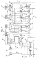
- an input shaft 5 which can be driven by a drive motor of a motor vehicle via a hydrodynamic torque converter, is connected to an output shaft 6 by means of two powershift clutches 9 and 10, respectively, via two partial transmissions 7 and 8 lying parallel to one another in the power flow, which are or can be brought into drive connection in the usual manner with at least one vehicle axle of the motor vehicle.
- One partial transmission 7 has four gear stages 11 to 14, with which the reverse gear R or the three forward gears I, III and V are formed.
- the two idler gears 22 and 23 of the gear stages 11 and 12 lying spatially next to one another can optionally be coupled with their countershaft 17 by an intermediate gear coupling 19, which is drawn in the neutral, disengaged position.
- the two idler gears 24 and 25 of the gear stages 13 and 14, which are spatially adjacent to one another, are connected by an intermediate gear clutch 20, which is drawn in its neutral, disengaged position, can optionally be coupled to the countershaft 17.
- the other sub-transmission 8 has a gear stage 15 with an idler gear 26 to form the second gear and a spatially adjacent gear stage 16 with an idler gear 27 to form the fourth gear.
- the two idler gears 26 and 27 can optionally be coupled by an intermediate gear clutch 21 with their countershaft 18, the gear clutch 21 being drawn in its neutral, disengaged position.
- the gear clutches 19 and 20 of the one sub-transmission 7 are engaged by preselection when the associated powershift clutch 9 is disengaged and the power flow is engaged by engaging the other powershift clutch 10 via one of the gear stages 15, 16 of the sub-transmission 8.
- gear clutch 21 of the other sub-transmission 8 is engaged by preselection when the associated powershift clutch 10 is disengaged and the power flow is engaged by engaging the other powershift clutch 9 via one of the gear stages 11 to 14 of the sub-transmission 7.
- the gear ratios of the gear stages 11 to 16 are coordinated with one another in such a way that for these gear changes also a change in the power flow from one Partial transmission takes place on the other.
- Overlap controls are known, cf.
- Förster The non-positive switching of gear ratios of vehicle transmissions" VDI-Zeitung 99 (1957) No. 27; 21st September.
- the method according to the invention enables a change between two gears formed in one and the same partial transmission, which are not adjacent to one another due to the aforementioned interpretation of the ratios of the gear stages without interrupting the tractive force.
- the method is described below for a downshift, for example from IV. To II. Gear, in particular with reference to FIG. 3, and for an upshift, for example from II. To IV. Gear, in particular with reference to FIG. 4.
- the powershift clutch 9 for engaging the partial transmission 7 in the drive connection between the input and output shafts 5 and 6 can be engaged by a clutch actuator 28 of the axial piston type and can be disengaged by spring means, not shown.
- a working pressure line 60 is connected to the clutch actuator 28, which leads to a clutch switching valve 62, which is fed by a main pressure line 64 and is controlled by an electromagnetic proportional valve 67 via a control pressure line 65.
- the powershift clutch 10 for engaging the partial transmission 8 in the drive connection between the input and output shafts 5 and 6 is engaged by a clutch actuator 29 of the axial piston type and disengaged by spring means, not shown. To act on its axial piston is to the
- Coupling actuator 29 is connected to a working pressure line 61, which leads to a clutch switching valve 63, which is fed by the main pressure line 64 and is controlled by an electromagnetic proportional valve 68 via a control pressure line 66.
- An electronic transmission control 86 which operates in a known manner as a function of input signals, in particular with regard to the driving speed, the engine load, the power requirement, the transmission state and a selector with the aid of stored shift lines, has outputs 87 and 90, which each have an output stage 88 or 91 are each connected to one of the proportional valves 67 and 68 by means of control lines 89 and 92, which are supplied with pressure via a secondary pressure line 69.
- the gear clutch 20 of the partial transmission 8 can be actuated by a shift actuator 70 of the axial piston type, which is held by resilient means in the central neutral position shown, in which the idler gears 24 and 25 are uncoupled from the countershaft 17.
- the switching actuator 70 can be switched into its two end positions by means of connected working pressure lines 71 and 72, which lead to a switching valve 73.
- the switching valve 73 fed by a secondary pressure line 74 can be controlled via a control pressure line 75 by an electromagnetic switching control valve 76, which is fed by a further secondary pressure line 77 and can be controlled by an output 93 of the transmission control 86 via an output stage 94 and a connected control line 95.
- the gear clutch 21 of the partial transmission 8 can be actuated by a shift actuator 78 of the axial piston type, which is held by resilient means in the central neutral position shown, in which the two idler gears 26 and 27 are uncoupled from the countershaft 18.
- the switching actuator 78 is in its two end positions can be switched by means of connected working pressure lines 79 and 80, which lead to a switching valve 81, which is fed by the secondary pressure line 74 and can be controlled via connected control pressure lines 82 and 84 by means of electromagnetic switching control valves 83 and 85, which are fed by the secondary pressure line 77.
- the shift control valves 83 and 85 can be controlled by means of connected control lines 98 and 101 with output stages 97 and 100 from outputs 96 and 99 of the transmission control 86.
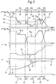
- FIG. 3 shows the sequence of a downshift from IVth gear to IInd gear in the gear change transmission of FIG. 1 in five switching phases.
- Fig. 3a the course of the working pressure p28 in the clutch actuator 28 of the powershift clutch 9 and the course of the working pressure p29 in the clutch actuator 29 of the powershift clutch 10 is shown over time t.
- 3b shows the profile of the clutch torque M K9 of the powershift clutch 9 as well as the profile of the clutch torque M K10 of the powershift clutch 10 over time t.
- Fig. 3c shows the course of the output torque M6 of the output shaft 6 over time t.
- Fig. 3d shows the course of the speed n5 of the input shaft 5 over time t again.
- the working pressure line 80 of the shift actuator 78 for actuating the gear clutch 21 into the position coupling the idler gear 27 to the countershaft 18 is connected by the switching valve 81 to the secondary pressure line 74, the shift control valve 85 excited by the transmission control 86 for the IV. Gear has controlled this switching valve 81 accordingly.
- the powershift clutch 9 is disengaged because the working pressure p28 in the associated clutch actuator 28 is switched off by the clutch control valve 62 with the help of the proportional valve 67.
- the electromagnetic shift control valve 76 excited by the transmission control 86 has switched the shift valve 73 into the position in which the working pressure line 71 for actuating the shift actuator 70 into the end position for coupling the idler gear 24 of the gear stage 13 of III.
- Ganges through the gear clutch 20 is connected to the secondary pressure line 74, so that in the partial transmission 7 of III. Gear is selected.
- a first shift phase 36 is triggered by corresponding signals at the outputs 87 and 90, in which the proportional valve 68 reduces the working pressure p29 of the clutch actuator 29
- Powershift clutch 10 causes a constant phase pressure value 38, which lies between the engagement pressure value 37 and a low contact pressure value 43 and allows the drive motor to continuously rev up, as is the steady increase 30 in the speed n5 between the speed value 32 corresponding to the IVth gear and the III .
- Gear corresponding speed value 34 shows.
- the pressure level is only so high that the drive motor can continue to rev up. If the working pressure p29 has dropped to the contact pressure value 43, a second switching phase 42 is triggered, in which the working pressure p29 of the clutch actuator 29 of the powershift clutch 10 is completely switched off and the working pressure p28 of the clutch actuator 28 of the powershift clutch 9 to a phase pressure value 44 is regulated, which between the contact pressure value 39 and the III. Gear associated engagement pressure value is and is only so high that the curve 30 of the speed n5 of the input shaft 5 continues to rise without the speed value of III. Ganges to stay.
- the increased phase pressure value 48 of the working pressure p28 is matched to the contact pressure value 43 of the working pressure p29 in such a way that both powershift clutches 9 and 10 transmit the engine torque, i.e. the torque of the input shaft 5 and the speed n5 of the input shaft 5 the speed value 33 of the 2nd gear is maintained.
- a fourth switching phase 49 is triggered, in which the overlapping control of the two working pressures p28 and p29 the powershift clutch 9 of the III. Gear switched off and the powershift clutch 10 of the 2nd gear is fully engaged, ie with the end of the fifth switching phase 49, the powershift clutch 10 transmits the full torque of the input shaft 5, the working pressure p29 then having reached the corresponding engagement pressure value 37 again.
- 3c illustrates the low-jerk course 35 of the output torque M6 of the output shaft 6 during the IV-II circuit according to the invention.
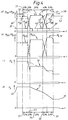
- a first shift phase 51 is triggered via corresponding signals at the outputs 87 and 90, in which the working pressure p29 in the clutch actuator 29 of the power shift clutch 10 under Initiated by the proportional valve 68 to an engagement pressure value 52, at which the powershift clutch 10 still transmits the full torque of the input shaft 5, while the proportional valve 67 at the clutch actuator 28 of the powershift clutch 9 initiates the filling process with control of working pressure p28, the latter via sets the duration of the filling process to an application pressure value 39.
- the speed n5 of the input shaft 5 does not change here.
- a second switching phase 53 is triggered, in which, using the usual overlap control for the relevant working pressures p28 and p29 the powershift clutch 9 engaged and the powershift clutch 10 disengaged so that this switching phase runs without interruption of the tractive force and still at a constant speed (speed value 33 of the lower II. gear) of the input shaft 5.
- fourth switching phase 56 is triggered, in which, using the usual overlap control for the affected working pressures p28 and p29, the powershift clutch 9 of III. Disengaged gear and the powershift clutch 10 of the fourth gear is engaged, this shift phase thus also running without interruption of the tractive force - but with control of the required pressure level with a continuously decreasing curve 31 of the speed n5 of the input shaft 5.
- the proportional valve 68 is caused by the transmission control 86 to lower the working pressure p29 in the clutch actuator 29 of the powershift clutch 10 of the IVth gear to approximately the engagement pressure value 52 regulate so that the speed n5 is kept at the speed value 32 of the fourth gear.
- Fig. 4b is self-interpreting in relation to the respective course of the clutch torque M K9 of the powershift clutch 9 and the clutch torque M K10 of the powershift clutch 10 due to the explanation of the pressure profiles of the associated working pressures p28 and p29 in Fig. 4a.
- 4c illustrates the jerk-free profile 59 of the output torque Msm of the output shaft 6, which deviates only slightly from a jerk-free profile, in the upshifting according to the invention over two gears.
Landscapes
- Engineering & Computer Science (AREA)
- General Engineering & Computer Science (AREA)
- Mechanical Engineering (AREA)
- Control Of Transmission Device (AREA)
- Friction Gearing (AREA)
Applications Claiming Priority (2)
| Application Number | Priority Date | Filing Date | Title |
|---|---|---|---|
| DE4031570A DE4031570C2 (de) | 1990-10-05 | 1990-10-05 | Anordnung zum selbsttätigen Schalten mittels Druckmittel-Hilfskraft eines Mehrwege-Zahnräderwechselgetriebes |
| DE4031570 | 1990-10-05 |
Publications (3)
| Publication Number | Publication Date |
|---|---|
| EP0478945A2 true EP0478945A2 (fr) | 1992-04-08 |
| EP0478945A3 EP0478945A3 (en) | 1993-10-20 |
| EP0478945B1 EP0478945B1 (fr) | 1996-06-05 |
Family
ID=6415669
Family Applications (1)
| Application Number | Title | Priority Date | Filing Date |
|---|---|---|---|
| EP91114222A Expired - Lifetime EP0478945B1 (fr) | 1990-10-05 | 1991-08-24 | Procédé de changement de vitesse automatique d'une transmission à roues dentées à positions multiples au moyen d'assistance par pression |
Country Status (4)
| Country | Link |
|---|---|
| US (1) | US5172602A (fr) |
| EP (1) | EP0478945B1 (fr) |
| DE (1) | DE4031570C2 (fr) |
| ES (1) | ES2090189T3 (fr) |
Cited By (8)
| Publication number | Priority date | Publication date | Assignee | Title |
|---|---|---|---|---|
| DE10232835A1 (de) * | 2002-07-19 | 2004-02-05 | Zf Friedrichshafen Ag | Doppelkupplungsgetriebe |
| WO2005008103A1 (fr) * | 2003-07-16 | 2005-01-27 | Volkswagen Aktiengesellschaft | Procede de commutation d'une boite de vitesses a double embrayage d'automobile |
| EP1435474A3 (fr) * | 2002-12-30 | 2005-10-05 | Volkswagen Aktiengesellschaft | Méthode d'amortissement de vibrations dans l'arbre de transmission et arbre de transmission |
| EP1304510A3 (fr) * | 2001-10-17 | 2007-02-28 | ZF FRIEDRICHSHAFEN Aktiengesellschaft | Procédé de commande d'une transmission à deux embrayages |
| EP1184597A3 (fr) * | 2000-08-29 | 2007-05-02 | Aisin Seiki Kabushiki Kaisha | Transmission à engrenage de type bi-axiale |
| DE102004001709B4 (de) * | 2004-01-13 | 2013-04-25 | Audi Ag | Antriebsaggregat für Kraftfahrzeuge |
| EP1450075B1 (fr) * | 2003-02-21 | 2013-12-04 | BorgWarner, Inc. | Procédé de commande d'une transmission à deux embrayages |
| DE102016114087A1 (de) | 2015-08-07 | 2017-02-09 | Avl List Gmbh | Verfahren zur Durchführung von Schaltvorgängen in einem Fahrzeugantriebsstrang |
Families Citing this family (33)
| Publication number | Priority date | Publication date | Assignee | Title |
|---|---|---|---|---|
| DE4137143A1 (de) * | 1991-11-12 | 1993-05-13 | Zahnradfabrik Friedrichshafen | Kraftfahrzeuggetriebe |
| GB2297811A (en) * | 1995-02-07 | 1996-08-14 | New Holland Belguim Nv | Transmission control sytem moves synchroniser to neutral and engages clutch for a predetermined time |
| DE19511897C2 (de) * | 1995-03-31 | 1999-06-02 | Daimler Chrysler Ag | Verfahren zum Steuern einer ein- und ausrückbaren Reibschlußverbindung bei einer Schaltungsvorrichtung eines automatischen Stufengetriebes eines Kraftfahrzeuges |
| DE19709417A1 (de) * | 1996-03-14 | 1997-10-30 | Luk Getriebe Systeme Gmbh | Vorrichtung zur Ansteuerung eines Drehmomentübertragungssystems und eines Getriebes, sowie ein Verfahren hierfür |
| DE19711820A1 (de) * | 1996-08-08 | 1998-09-24 | Volkswagen Ag | Verfahren zum Schalten eines Doppelkupplungsgetriebes und Doppelkupplungsgetriebe |
| US6145398A (en) * | 1998-02-20 | 2000-11-14 | New Venture Gear, Inc. | Electronically controlled shift system for a manual transmission |
| RU2002131942A (ru) * | 2000-04-28 | 2004-05-27 | Лук Ламеллен Унд Купплюнгсбау Бетайлигунгс Кг (De) | Управляющее устройство для коробки передач с двухдисковым сцеплением |
| JP2001336631A (ja) * | 2000-05-30 | 2001-12-07 | Aisin Ai Co Ltd | 自動変速装置の制御装置 |
| JP3293613B2 (ja) * | 2000-06-23 | 2002-06-17 | 株式会社日立製作所 | 自動車用制御装置,自動車の制御方法,変速機 |
| WO2002055910A1 (fr) * | 2001-01-12 | 2002-07-18 | Zf Sachs Ag | Procede permettant de faire fonctionner un ensemble transmission possedant un dispositif embrayage multiple et une boite de vitesse couplable sous charge, et ensemble transmission de ce type dote d'une unite de commande correspondante |
| DE10133919A1 (de) * | 2001-07-12 | 2003-01-23 | Bayerische Motoren Werke Ag | Elektromechanisches Getriebe |
| EP1353095A1 (fr) * | 2002-04-10 | 2003-10-15 | Van Doorne's Transmissie B.V. | Méthode de commande pour une transmission automatique |
| DE10393110D2 (de) | 2002-09-25 | 2005-05-25 | Luk Fahrzeug Hydraulik | Schaltstrategie und Getriebesteuerung für ein Getriebe, insbesondere für ein Doppelkupplungsgetriebe |
| DE50310550D1 (de) * | 2002-10-16 | 2008-11-06 | Luk Lamellen & Kupplungsbau | Getriebe und verfahren zum ansteuern einer kupplung, insbesondere einer doppelkupplung |
| US6832978B2 (en) * | 2003-02-21 | 2004-12-21 | Borgwarner, Inc. | Method of controlling a dual clutch transmission |
| KR100569140B1 (ko) * | 2003-12-10 | 2006-04-07 | 현대자동차주식회사 | 이중 클러치 변속기 |
| DE102004046558A1 (de) * | 2004-09-24 | 2006-04-06 | Volkswagen Ag | Sensoranordnung und Verfahren zur Steuerung eines automatisierten Doppelkupplungsgetriebes |
| EP1994299B1 (fr) * | 2006-03-02 | 2012-05-16 | Volvo Lastvagnar Ab | Procédé et dispositif de commande d'un embrayage à disque |
| JP5091514B2 (ja) * | 2007-03-20 | 2012-12-05 | 株式会社小松製作所 | 産業車両用変速機 |
| DE102007033927B4 (de) * | 2007-07-20 | 2017-03-09 | Volkswagen Ag | Verfahren zur Steuerung der Schaltungen eines Doppelkupplungsgetriebes eines Kraftfahrzeuges, insbesondere eines automatischen Doppelkupplungsgetriebes |
| KR101316314B1 (ko) | 2011-06-09 | 2013-10-08 | 기아자동차주식회사 | 차량의 dct 제어방법 |
| KR101305842B1 (ko) | 2011-06-09 | 2013-09-06 | 기아자동차주식회사 | 차량의 더블클러치변속기 제어방법 |
| KR101305852B1 (ko) | 2011-06-09 | 2013-09-06 | 현대자동차주식회사 | 차량의 변속기 제어방법 |
| EP2828621B1 (fr) | 2012-03-23 | 2017-09-06 | Pacific Rim Engineered Products (1987) Ltd. | Mécanisme d'engagement d'engrenage pour transmissions et procédés associés |
| CN104395648B (zh) | 2012-03-23 | 2017-06-30 | 环太平洋工程产品(1987)有限公司 | 具有提供替选传动比的替选扭矩传输路径的双离合器式动力变速器 |
| JP5947086B2 (ja) * | 2012-04-02 | 2016-07-06 | ダイムラー・アクチェンゲゼルシャフトDaimler AG | 車両の変速制御装置 |
| US10830313B2 (en) | 2014-11-21 | 2020-11-10 | Avl Powertrain Engineering, Inc. | Dual-clutch transmission with planetary gearset and multiple first gears |
| US10221921B2 (en) | 2014-11-21 | 2019-03-05 | Avl Powertrain Engineering, Inc. | Torque split dual-clutch transmission |
| US9897165B2 (en) * | 2014-11-21 | 2018-02-20 | Avl Power Train Engineering, Inc. | Dual-clutch transmission with multiple first gears |
| KR101694029B1 (ko) | 2015-07-09 | 2017-01-09 | 현대자동차주식회사 | 차량의 dct 변속 제어방법 |
| KR101673814B1 (ko) * | 2015-10-08 | 2016-11-08 | 현대자동차주식회사 | 차량의 변속 제어방법 |
| US9651145B1 (en) * | 2015-11-13 | 2017-05-16 | GM Global Technology Operations LLC | Transmission gear shifting |
| CN108340766B (zh) * | 2018-01-03 | 2021-06-04 | 北京理工大学 | 混合动力系统、车辆及其控制方法 |
Family Cites Families (10)
| Publication number | Priority date | Publication date | Assignee | Title |
|---|---|---|---|---|
| JPS53132659A (en) * | 1977-04-22 | 1978-11-18 | Toyota Motor Corp | Oil pressure control device of automatic transmission |
| DE2848624A1 (de) * | 1978-11-09 | 1980-05-22 | Bosch Gmbh Robert | Verfahren zur beeinflussung einer brennkraftmaschine und vorrichtung zur durchfuehrung des verfahrens |
| JPS59155650A (ja) * | 1983-02-21 | 1984-09-04 | Nissan Motor Co Ltd | 自動変速機の油圧制御装置 |
| US4513631A (en) * | 1983-06-16 | 1985-04-30 | General Motors Corporation | Dual input clutch transmission |
| JPS6145163A (ja) * | 1984-08-10 | 1986-03-05 | Hitachi Ltd | 自動変速システム |
| JPH0663560B2 (ja) * | 1985-08-21 | 1994-08-22 | 三菱自動車工業株式会社 | 車両用自動変速機 |
| JPS63167162A (ja) * | 1986-12-27 | 1988-07-11 | Isuzu Motors Ltd | 電子制御自動変速機の制御装置 |
| JP2791660B2 (ja) * | 1987-04-10 | 1998-08-27 | 株式会社小松製作所 | 変速機の制御装置 |
| DE4017961A1 (de) * | 1989-06-10 | 1990-12-13 | Zahnradfabrik Friedrichshafen | Steuersystem fuer ein lastschaltbares doppel-kupplungsgetriebe |
| DE4000832C1 (en) * | 1990-01-13 | 1991-02-14 | Mercedes-Benz Aktiengesellschaft, 7000 Stuttgart, De | Gear change transmission with lay shaft - has advance shift gear stage in force transmission path of partial gear train(s) |
-
1990
- 1990-10-05 DE DE4031570A patent/DE4031570C2/de not_active Expired - Fee Related
-
1991
- 1991-08-24 EP EP91114222A patent/EP0478945B1/fr not_active Expired - Lifetime
- 1991-08-24 ES ES91114222T patent/ES2090189T3/es not_active Expired - Lifetime
- 1991-10-05 US US07/772,659 patent/US5172602A/en not_active Expired - Fee Related
Cited By (12)
| Publication number | Priority date | Publication date | Assignee | Title |
|---|---|---|---|---|
| EP1184597A3 (fr) * | 2000-08-29 | 2007-05-02 | Aisin Seiki Kabushiki Kaisha | Transmission à engrenage de type bi-axiale |
| EP1304510A3 (fr) * | 2001-10-17 | 2007-02-28 | ZF FRIEDRICHSHAFEN Aktiengesellschaft | Procédé de commande d'une transmission à deux embrayages |
| DE10232835A1 (de) * | 2002-07-19 | 2004-02-05 | Zf Friedrichshafen Ag | Doppelkupplungsgetriebe |
| DE10232835B4 (de) * | 2002-07-19 | 2010-02-11 | Zf Friedrichshafen Ag | Doppelkupplungsgetriebe |
| EP1435474A3 (fr) * | 2002-12-30 | 2005-10-05 | Volkswagen Aktiengesellschaft | Méthode d'amortissement de vibrations dans l'arbre de transmission et arbre de transmission |
| EP1450075B1 (fr) * | 2003-02-21 | 2013-12-04 | BorgWarner, Inc. | Procédé de commande d'une transmission à deux embrayages |
| WO2005008103A1 (fr) * | 2003-07-16 | 2005-01-27 | Volkswagen Aktiengesellschaft | Procede de commutation d'une boite de vitesses a double embrayage d'automobile |
| DE102004001709B4 (de) * | 2004-01-13 | 2013-04-25 | Audi Ag | Antriebsaggregat für Kraftfahrzeuge |
| DE102016114087A1 (de) | 2015-08-07 | 2017-02-09 | Avl List Gmbh | Verfahren zur Durchführung von Schaltvorgängen in einem Fahrzeugantriebsstrang |
| CN106438995A (zh) * | 2015-08-07 | 2017-02-22 | Avl里斯脱有限公司 | 一种在车辆传动系中实现换挡过程的方法 |
| AT517581B1 (de) * | 2015-08-07 | 2017-03-15 | Avl List Gmbh | Verfahren zur durchführung von schaltvorgängen in einem fahrzeugantriebsstrang |
| AT517581A4 (de) * | 2015-08-07 | 2017-03-15 | Avl List Gmbh | Verfahren zur durchführung von schaltvorgängen in einem fahrzeugantriebsstrang |
Also Published As
| Publication number | Publication date |
|---|---|
| US5172602A (en) | 1992-12-22 |
| EP0478945B1 (fr) | 1996-06-05 |
| EP0478945A3 (en) | 1993-10-20 |
| DE4031570C2 (de) | 1995-10-12 |
| DE4031570A1 (de) | 1992-04-09 |
| ES2090189T3 (es) | 1996-10-16 |
Similar Documents
| Publication | Publication Date | Title |
|---|---|---|
| EP0478945B1 (fr) | Procédé de changement de vitesse automatique d'une transmission à roues dentées à positions multiples au moyen d'assistance par pression | |
| EP2037160B1 (fr) | Procédé de commande de changement de vitesse d'une boîte de vitesse à plusieurs groupes automatisée | |
| EP2376814B1 (fr) | Procédé pour faire fonctionner un système de transmission | |
| EP2524156B1 (fr) | Procédé pour faire fonctionner un dispositif de transmission comprenant plusieurs éléments de changement de vitesse à friction et au moins un élément de changement de vitesse à complémentarité de forme | |
| EP0517705B1 (fr) | Procede de changement de vitesse dans une transmission a variation discontinue de la vitesse | |
| DE60207135T2 (de) | Automatikgetriebe | |
| DE3207938C2 (de) | Unter Last schaltbare mechanische Getriebeanordnung | |
| EP1031769B1 (fr) | Boíte de vitesses robotisée pour véhicule et système de commande pour une telle boíte de vitesses | |
| EP2630393A1 (fr) | Boîte de vitesses couplable sous charge | |
| DE19844783C1 (de) | Verfahren zum Schalten eines Zahnräderwechselgetriebes | |
| DE4320858A1 (de) | Vorrichtung zum Steuern eines Automatikgetriebes | |
| DE69012744T2 (de) | Schaltungssteuerungssystem eines automatischen Getriebes. | |
| DE4014603C2 (de) | Getriebe mit Einwegkupplungen und Vorrichtung zur Steuerung des Getriebes | |
| DE19924501A1 (de) | Lastschaltbares Stufenwechselgetriebe | |
| EP1438525A1 (fr) | Procede de commande de boite de vitesses a plusieurs groupes | |
| DE10317144A1 (de) | Mehrachsen-Planetengetriebe | |
| DE19814569C2 (de) | Zahnräderwechselgetriebe mit einem Zahnräder-Synchronisiergetriebe | |
| DE19853825C1 (de) | Kraftfahrzeug-Antriebsstrang und Verfahren zum Steuern eines Schaltvorganges eines Kraftfahrzeug-Antriebsstranges | |
| DE69202835T2 (de) | Öldrucksteuerung für automatisches Fahrzeuggetriebe. | |
| EP2870384B1 (fr) | Procédé de fonctionnement d'une boite de vitesses automatique | |
| DE19861303B4 (de) | Stufengetriebe und Verfahren zum Auslegen eines Ganges eines Stufengetriebes | |
| DE3836421C2 (de) | Elektrohydraulische Steuereinrichtung für ein automatisches Schaltgetriebe | |
| DE69202931T2 (de) | Steuervorrichtung für automatisches Fahrzeuggetriebe. | |
| DE3700380A1 (de) | Lastschaltgetriebe | |
| DE3840733C2 (fr) |
Legal Events
| Date | Code | Title | Description |
|---|---|---|---|
| PUAI | Public reference made under article 153(3) epc to a published international application that has entered the european phase |
Free format text: ORIGINAL CODE: 0009012 |
|
| AK | Designated contracting states |
Kind code of ref document: A2 Designated state(s): ES FR GB IT |
|
| PUAL | Search report despatched |
Free format text: ORIGINAL CODE: 0009013 |
|
| AK | Designated contracting states |
Kind code of ref document: A3 Designated state(s): ES FR GB IT |
|
| 17P | Request for examination filed |
Effective date: 19930918 |
|
| 17Q | First examination report despatched |
Effective date: 19950927 |
|
| GRAH | Despatch of communication of intention to grant a patent |
Free format text: ORIGINAL CODE: EPIDOS IGRA |
|
| ITF | It: translation for a ep patent filed | ||
| GRAA | (expected) grant |
Free format text: ORIGINAL CODE: 0009210 |
|
| AK | Designated contracting states |
Kind code of ref document: B1 Designated state(s): ES FR GB IT |
|
| GBT | Gb: translation of ep patent filed (gb section 77(6)(a)/1977) |
Effective date: 19960627 |
|
| ET | Fr: translation filed | ||
| REG | Reference to a national code |
Ref country code: ES Ref legal event code: FG2A Ref document number: 2090189 Country of ref document: ES Kind code of ref document: T3 |
|
| REG | Reference to a national code |
Ref country code: ES Ref legal event code: FG2A Ref document number: 2090189 Country of ref document: ES Kind code of ref document: T3 |
|
| PLBE | No opposition filed within time limit |
Free format text: ORIGINAL CODE: 0009261 |
|
| STAA | Information on the status of an ep patent application or granted ep patent |
Free format text: STATUS: NO OPPOSITION FILED WITHIN TIME LIMIT |
|
| 26N | No opposition filed | ||
| REG | Reference to a national code |
Ref country code: GB Ref legal event code: 732E |
|
| REG | Reference to a national code |
Ref country code: FR Ref legal event code: TP |
|
| REG | Reference to a national code |
Ref country code: GB Ref legal event code: 732E |
|
| PGFP | Annual fee paid to national office [announced via postgrant information from national office to epo] |
Ref country code: GB Payment date: 20010713 Year of fee payment: 11 |
|
| PGFP | Annual fee paid to national office [announced via postgrant information from national office to epo] |
Ref country code: FR Payment date: 20010801 Year of fee payment: 11 |
|
| PGFP | Annual fee paid to national office [announced via postgrant information from national office to epo] |
Ref country code: ES Payment date: 20010803 Year of fee payment: 11 |
|
| REG | Reference to a national code |
Ref country code: GB Ref legal event code: IF02 |
|
| PG25 | Lapsed in a contracting state [announced via postgrant information from national office to epo] |
Ref country code: GB Free format text: LAPSE BECAUSE OF NON-PAYMENT OF DUE FEES Effective date: 20020824 |
|
| PG25 | Lapsed in a contracting state [announced via postgrant information from national office to epo] |
Ref country code: ES Free format text: LAPSE BECAUSE OF NON-PAYMENT OF DUE FEES Effective date: 20020825 |
|
| GBPC | Gb: european patent ceased through non-payment of renewal fee |
Effective date: 20020824 |
|
| PG25 | Lapsed in a contracting state [announced via postgrant information from national office to epo] |
Ref country code: FR Free format text: LAPSE BECAUSE OF NON-PAYMENT OF DUE FEES Effective date: 20030430 |
|
| REG | Reference to a national code |
Ref country code: FR Ref legal event code: ST |
|
| REG | Reference to a national code |
Ref country code: ES Ref legal event code: FD2A Effective date: 20030912 |
|
| PG25 | Lapsed in a contracting state [announced via postgrant information from national office to epo] |
Ref country code: IT Free format text: LAPSE BECAUSE OF NON-PAYMENT OF DUE FEES;WARNING: LAPSES OF ITALIAN PATENTS WITH EFFECTIVE DATE BEFORE 2007 MAY HAVE OCCURRED AT ANY TIME BEFORE 2007. THE CORRECT EFFECTIVE DATE MAY BE DIFFERENT FROM THE ONE RECORDED. Effective date: 20050824 |