EP0478966A2 - Discriminateur numérique de correspondance de phase pour alimentation triphasée - Google Patents
Discriminateur numérique de correspondance de phase pour alimentation triphasée Download PDFInfo
- Publication number
- EP0478966A2 EP0478966A2 EP91114804A EP91114804A EP0478966A2 EP 0478966 A2 EP0478966 A2 EP 0478966A2 EP 91114804 A EP91114804 A EP 91114804A EP 91114804 A EP91114804 A EP 91114804A EP 0478966 A2 EP0478966 A2 EP 0478966A2
- Authority
- EP
- European Patent Office
- Prior art keywords
- phase
- load
- source
- power source
- phase power
- Prior art date
- Legal status (The legal status is an assumption and is not a legal conclusion. Google has not performed a legal analysis and makes no representation as to the accuracy of the status listed.)
- Granted
Links
Images



Classifications
-
- H—ELECTRICITY
- H02—GENERATION; CONVERSION OR DISTRIBUTION OF ELECTRIC POWER
- H02J—ELECTRIC POWER NETWORKS; CIRCUIT ARRANGEMENTS OR SYSTEMS FOR SUPPLYING OR DISTRIBUTING ELECTRIC POWER; SYSTEMS FOR STORING ELECTRIC ENERGY
- H02J3/00—Circuit arrangements for AC mains or AC distribution networks
- H02J3/38—Arrangements for feeding a single network from two or more generators or sources in parallel; Arrangements for feeding already energised networks from additional generators or sources in parallel
Definitions
- the invention disclosed broadly relates to the switching of multi-phase electrical power sources, and more particularly, relates to the precise matching of the relative phases in a multi-phase system for switching between power sources.
- Delta power systems and some unreferenced Y power systems are commonly used in power generation and distribution networks. These are normally three-phase power sources.
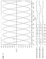
- the voltage waveforms of a three-phase power system are shown in Fig. 1.
- three-phase voltage waveforms are represented by Phase A, Phase B and Phase C, which are generated so as to be 120 degrees in phase separation, respectively.
- the measurement of the relative phase relation between two sources in a multi-phase system is important in power switching control applications.
- phase rotation detection unit is used when switching from one power source to an asynchronous second source.
- This device most closely matches the phase of the load to the second power source.
- the phase rotation-go/no go unit of Ross/Woodworth can be accomplished by the digital phase match discrimination of the present invention.
- Matchup in this case is defined as finding, for each phase (commonly labeled A, B or C) of the load, that phase of the second source which is closest in time (phase angle).
- phase rotation direction for this disclosure will always be taken to be to A to B to C, but the solution is also applicable for sources with A to C to B rotation provided all sources have the same rotation.
- the problem is to establish real time knowledge of the angle of rotation of the required waveforms of sufficient accuracy to calculate the best of three matchups with a tolerable worst case error. Error is due to the difference in source frequencies and source waveform sampling rate. This can be achieved with a logic system that receives as data the zero-voltage crossing of the three waveforms from each source or from the load and the "new" source.
- the invention includes a "polarity change detector” which detects any change of polarity in any of the three phases of the present or new power source or the load.
- a "logic network” produces outputs based on the inputs provided from the load and the new source or from both sources and the present source-to-load configuration.
- the logic network outputs and derived from a known lookup table.
- the output from the logic network is latched by a sampling clock derived from the "polarity change detector” circuit.
- the output of the latch provides the best phase-matching solution at any given time.
- Fig. 1 shows three phases, A, B and C for a three-phase power system.
- the three phases of the power system are 120 degrees apart.
- phases B and C are equal and opposite.
- This zero-voltage cross-over detection scheme is disclosed in USP 4,901,005 to Shin and Woodworth, entitled “Zero Voltage Crossover Detector for Poly-Phase Systems" wherein a scheme for detecting zero crossing of one phase of a three-phase power supply is disclosed.
- the waveform polarities A, B and C are shown in the waveform polarities A, B and C.
- the problem is to resolve the relative phases of an asynchronous, three-phase power source and a load driven by a second, similar source, such that an optimal phase to phase matchup can be made between them while preserving the phase rotation direction.
- the matchup in this case is defined as finding, for each phase commonly labeled A, B and C, of the load that phase of the second or "new" source which is closest in phase angle.
- Analysis of the problem demonstrates that given typical power sources with three-phases at 120 degrees with respect to each other, the best of three matchups yield a theoretical worst case angular discontinuity of 60 degrees.
- the problem then is to establish real time knowledge of the angular rotation and the required waveforms with sufficient accuracy to calculate the best of three matchups with a tolerable worst case error.
- This can be achieved with a logic system that receives a data point and a zero voltage crossing of the three waveforms from each source or from the load and the "new" source.
- This phase matchup can be seen in Fig. 3, wherein the power source 1 has it's A Phase at peak voltage and power source 2 has it's A Phase 60 degrees advanced from power source 1.
- the theoretical 60 degree angular misalignment shown is the worst case possible.
- Fig. 4a shows a truth table for the connection of the load to the new source based on the polarities it derived from the load and new source waveforms for the six different states as shown in Fig. 1. Only three available paths are allowable for converting the new source to the load. That is, A to A, A to B, or A to C with the phase of the new source matching the corresponding phase of the load.
- New path 1 connects new source phase A to load A, source B to load B and source C to load C.
- New path 2 connects source A to load B, source B to load C, and source C to load A.
- New path 3 connects course A to load C, source B to load A and source C to load B.
- Fig. 4b shows a truth table for the connection of the load to new source using both source voltage polarities to find the new path.
- To use the translation truth table note the angular location of where a phase of the present source is and a positive peak, or at any other convenient reference point. Knowing which phase it is (A, B or C), select the appropriate row in the translation table. Then note the present path (1, 2 or 3) being used and select the appropriate column in the table. The intersection of the row and column selected is the load phase which should be used in the "new path" truth table of Fig. 4a. This method is called “method B.”
- Fig. 5a Shown in Fig. 5a is an embodiment of the present invention for the circuit which analyzes the angular position of an asynchronous alternating current (AC) three-phase voltage source and the load.
- the circuit provides an output based upon the angular displacement of the new source and load (method A).
- the output is used to select one connection path from a set of three available connection paths which would allow a transfer of power from the present source to the new source with an angular shift at the electrical load of no more than 60 electrical degrees.
- Element 50 is a register.
- Element 58 detects a change of voltage polarity on any of the three new source phases.
- a change of voltage polarity represents a transition from a positive voltage to a negative voltage, or from a negative voltage to a positive voltage.
- a sampling clock 52 is used to latch the state of the new source polarities into the storage device register 50. This creates a history of the new source polarities at the output of the register. The history has a maximum time lapse equal to the time period of the sampling clock.
- Element 58 compares a history of each phase polarity to the corresponding real time phase polarity. If any real time phase polarity is not equivalent to its corresponding history value, a change in polarity output is generated.
- PROM element 54 analyzes the angular displacement dynamics of the asynchronous source and the load and calculates which matrix connection of the new source to the load will cause the least amount of angular shift of the load if the source of power to the load were to switch from the present source to the new source.
- PROM 54 is a logic network which updates its output whenever its inputs change.
- the inputs to PROM 54 consist of either the load and new source polarities or the present and new source polarities and the "present path."
- the present path describes the matrix connection on the present source to the load. For example, if source phase A is connected to load phase A, source B to load B, and source C to load C, this is one connection. If source phase A is connected to load phase B, source B to load C and source C to load A, this a second possible connection. The third connection exists when source A connects to load C, source B to load A and source C to load B. The present path describes which of these three connections are being used to provide power to the load from the present source.
- PROM 54 continuously monitors the three-phase polarities of the source or load waveforms and calculates a new path which yields the best alignment of phases between the new source and the load.
- the output of PROM 54 is the new phase match path, or "new path.”
- Register 56 is a latching device which latches a new path output from PROM 54 in a storage device at moments of time controlled by the output of element 58, or when a change of polarity is detected in any phase of the new source. This means that on average the "new path" is latched every 60 electrical degrees with respect to the new source. The new path is latched after every change of new source polarity for the following reason: When a change in any phase polarity is detected for a source, the angular position of the three-phase source is exactly known. Monitoring the source polarity is an efficient, accurate method for determining the actual angular position of the source voltage. The accuracy of the position of the source is subject only to the delays associated with detecting and reporting the change in the polarity. This time delay has a small effect on the accuracy of the circuit output in the form of an implementation dependent error factor. This sampling method is valid regardless of which source (present or new) is monitored for polarity changes.
- the circuit described allows an external power transfer control circuit to transfer power to an electrical load from an AC power source to another asynchronous AC power source with a maximum angular displacement at the load of 60 electrical degrees.
- the circuit may use information about the present connection path of a source to a load along with information about the voltage polarities of both the source which is powering the load at a defined time and a source which is available to provide power to the load. Alternately, the circuit may utilize new source and load voltage polarity information.
- the circuit calculates which connection path between the new source and the load should be selected to allow a transfer of power from the present source to the new source to occur with an angular shift on the load of no more than 60 electrical degrees.
- FIG. 5b A block diagram of an embodiment of the invention using voltage polarity signals from both power sources and the present path to the load is shown in Fig. 5b. It operates in the same manner as the circuit as described in relation to Fig. 5a with the addition of "present path" signals to the PROM 54.
- the polarity change detector 58 shown in Figs. 5a and b can be realized in the embodiment as shown in Fig. 6.
- Register 50 is connected to the sample clock 52 and receives the source waveform polarities.
- Register 50 outputs delayed signals to a set of exclusive OR gates.
- Exclusive OR gates 64, 66 and 68 provide a logically "true” signal when the waveform has changed state. When any of the polarities have changed state, a "logically true” is produced at the output of the OR gate 70.
- Register 62 outputs its signal to output register 56 to latch the new path 80 which is valid until the next change of polarity is detected. Both method A and method B implementations are shown in Fig. 6.
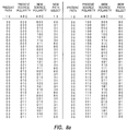
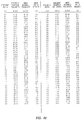
- the PROM is programmed to output the lookup table shown in Fig. 7. For six inputs, three from the new power source and three from the load, there are 64 possible values. Each input combination produces a best match as determined by the truth table of Fig. 4a. If the polarities from both sources are used and the present path is included, the lookup table consists of 256 entries (eight inputs). The listing of these values is shown in Fig. 8. The solution is determined by the translation table and truth table in Figs. 4a and b.
- the new path decoding (a phase match selection) 80 is represented by: 00 - invalid path; 01 - new source phase A to load phase A, B to B, and C to C; 10 new source phase A to load phase B, B to C, C to A; and 11 - new source phase A to load phase C; B to A, C to B.
- the polarity lines are represented by 0 for a negative voltage and 1 for a positive voltage. Referring to Fig. 1, the states of phases are represented as follows: 0 - 60 degrees : A+, B-, C+ ; state 101. 60 - 120 degrees : A+, B-, C- ; state 100. 120 - 180 degrees : A+, B+, C- ; state 110.
- 180 - 240 degrees A-, B+, C- ; state 010.
- 240 - 300 degrees A-, B+, C+ ; state 011.
- 300 - 360 degrees A-, B-, C+ ; state 001.
Landscapes
- Engineering & Computer Science (AREA)
- Power Engineering (AREA)
- Supply And Distribution Of Alternating Current (AREA)
- Measuring Phase Differences (AREA)
- Ac-Ac Conversion (AREA)
Applications Claiming Priority (2)
| Application Number | Priority Date | Filing Date | Title |
|---|---|---|---|
| US07/592,748 US5212407A (en) | 1990-10-04 | 1990-10-04 | Digital phase match discriminator for three-phase power |
| US592748 | 1990-10-04 |
Publications (3)
| Publication Number | Publication Date |
|---|---|
| EP0478966A2 true EP0478966A2 (fr) | 1992-04-08 |
| EP0478966A3 EP0478966A3 (en) | 1992-10-28 |
| EP0478966B1 EP0478966B1 (fr) | 1995-12-13 |
Family
ID=24371913
Family Applications (1)
| Application Number | Title | Priority Date | Filing Date |
|---|---|---|---|
| EP19910114804 Expired - Lifetime EP0478966B1 (fr) | 1990-10-04 | 1991-09-03 | Discriminateur numérique de correspondance de phase pour alimentation triphasée |
Country Status (4)
| Country | Link |
|---|---|
| US (1) | US5212407A (fr) |
| EP (1) | EP0478966B1 (fr) |
| JP (1) | JP2582962B2 (fr) |
| DE (1) | DE69115419T2 (fr) |
Cited By (3)
| Publication number | Priority date | Publication date | Assignee | Title |
|---|---|---|---|---|
| EP0567801A3 (fr) * | 1992-04-30 | 1994-03-23 | Ibm | |
| US20200269182A1 (en) * | 2017-09-05 | 2020-08-27 | Husqvarna Ab | Separator, separator system and methods of their operation |
| US11185808B2 (en) * | 2017-09-05 | 2021-11-30 | Husqvarna Ab | Separator and method of operating a separator |
Families Citing this family (4)
| Publication number | Priority date | Publication date | Assignee | Title |
|---|---|---|---|---|
| EP0681755B1 (fr) * | 1993-01-29 | 1996-09-04 | Citeq | Procede et appareil d'interconnexion de deux reseaux a courant alternatif polyphase synchrone |
| DE19653323C2 (de) * | 1996-12-20 | 2001-07-12 | Beha C Gmbh | Vorrichtung zur Bestimmung des Vorzeichens einer Phasenverschiebung zweier elektrischer Signale |
| US8856557B2 (en) | 2010-06-03 | 2014-10-07 | International Business Machines Corporation | Digital power balancing controller |
| CN110138001A (zh) * | 2018-02-09 | 2019-08-16 | 无锡美凯能源科技有限公司 | 一种应用于微电网逆变装置的相序识别及自调整方法 |
Family Cites Families (12)
| Publication number | Priority date | Publication date | Assignee | Title |
|---|---|---|---|---|
| GB1144897A (en) * | 1965-06-21 | 1969-03-12 | Rotax Ltd | Method and apparatus for use when connecting together two a.c. supplies |
| US4021704A (en) * | 1976-02-27 | 1977-05-03 | Borg-Warner Corporation | Phase sequence correcting system for three-phase AC power |
| US4218625A (en) * | 1978-01-25 | 1980-08-19 | Beckwith Robert W | Synchronizing check relay |
| US4308465A (en) * | 1979-05-25 | 1981-12-29 | General Electric Company | Frequency control for paralleled AC systems |
| US4427933A (en) * | 1981-10-30 | 1984-01-24 | Westinghouse Electric Corp. | Load commutated inverter gating control system and motor drive with such control system |
| US4499534A (en) * | 1982-10-12 | 1985-02-12 | Borg-Warner Corporation | Control system for controlling an SCR network to regulate three-phase A-C power flow |
| CA1193351A (fr) * | 1983-06-14 | 1985-09-10 | Gerald Roberge | Methode et systeme d'interconnexion de reseaux triphases syncrones au asynchrones au moyen d'impedances reactives variables |
| US4677264A (en) * | 1984-12-24 | 1987-06-30 | Mitsubishi Denki Kabushiki Kaisha | Contact material for vacuum circuit breaker |
| DE3562962D1 (en) * | 1985-01-21 | 1988-06-30 | Siemens Ag | Method for connecting electric synchronous machines and/or alternating current electric networks in parallel |
| US4761563A (en) * | 1987-10-27 | 1988-08-02 | International Business Machines Corporation | Asynchronous multiphase switching gear |
| US4901005A (en) * | 1988-12-05 | 1990-02-13 | International Business Machines Corporation | Zero voltage crossover detector for polyphase systems |
| US4937462A (en) * | 1989-01-23 | 1990-06-26 | Sundstrand Corporation | No break power transfer control for a VSCF power generating system |
-
1990
- 1990-10-04 US US07/592,748 patent/US5212407A/en not_active Expired - Fee Related
-
1991
- 1991-07-30 JP JP19033591A patent/JP2582962B2/ja not_active Expired - Lifetime
- 1991-09-03 DE DE69115419T patent/DE69115419T2/de not_active Expired - Fee Related
- 1991-09-03 EP EP19910114804 patent/EP0478966B1/fr not_active Expired - Lifetime
Cited By (4)
| Publication number | Priority date | Publication date | Assignee | Title |
|---|---|---|---|---|
| EP0567801A3 (fr) * | 1992-04-30 | 1994-03-23 | Ibm | |
| US20200269182A1 (en) * | 2017-09-05 | 2020-08-27 | Husqvarna Ab | Separator, separator system and methods of their operation |
| US11185808B2 (en) * | 2017-09-05 | 2021-11-30 | Husqvarna Ab | Separator and method of operating a separator |
| US11607640B2 (en) * | 2017-09-05 | 2023-03-21 | Husqvarna Ab | Separator, separator system and methods of their operation |
Also Published As
| Publication number | Publication date |
|---|---|
| JP2582962B2 (ja) | 1997-02-19 |
| US5212407A (en) | 1993-05-18 |
| EP0478966A3 (en) | 1992-10-28 |
| EP0478966B1 (fr) | 1995-12-13 |
| DE69115419D1 (de) | 1996-01-25 |
| DE69115419T2 (de) | 1996-06-20 |
| JPH0662534A (ja) | 1994-03-04 |
Similar Documents
| Publication | Publication Date | Title |
|---|---|---|
| EP0478966B1 (fr) | Discriminateur numérique de correspondance de phase pour alimentation triphasée | |
| US5796259A (en) | Methods and apparatus for detection of fault direction | |
| EP0397932B1 (fr) | Dispositif de commande d'un filtre actif | |
| US5959858A (en) | Electric power conversion apparatus | |
| US5523937A (en) | Frequency converter, procedure for controlling it and motor control using a frequency converter | |
| US5311066A (en) | Universal phase match path generator for three-phase power | |
| KR100187965B1 (ko) | 변환기의 전기밸브 제어방법 | |
| JP3551373B2 (ja) | 系統連系用電力変換装置及びその制御方法 | |
| EP1204198B1 (fr) | Procédé et système pour la détection d'un niveau zéro de courant dans un convertisseur commuté par réseau | |
| US4710703A (en) | Direction sensing system for an AC power supply and AC motor drive with such direction sensing system | |
| US4873619A (en) | Method and apparatus for controlling a static converter at an asymetrical network | |
| JP2000287453A (ja) | 多重電力変換装置 | |
| WO1995034125A1 (fr) | Methode pour determiner la vitesse de rotation, la grandeur et la direction instantanee d'un flux | |
| RU1774433C (ru) | Импульсный синхронизатор | |
| EP0583875B1 (fr) | Procédé et appareil de cÔntrole d'un convertisseur de puissance | |
| SU1272327A1 (ru) | Устройство импульсного регулировани мощности в @ -фазной сети без нейтрали | |
| SU1372543A1 (ru) | Способ управлени трехфазным непосредственным преобразователем частоты | |
| RU2084073C1 (ru) | Устройство управления параллельным инвертором | |
| EP0711028A2 (fr) | Dispositif de commande pour convertisseur de puissance | |
| SU938260A1 (ru) | Система управлени тиристорным электроприводом | |
| SU943986A1 (ru) | Устройство автоматического прекращени асинхронного хода в энергосистеме | |
| JP3553180B2 (ja) | コンバータ装置 | |
| SU1103331A1 (ru) | Цифровое фазосдвигающее устройство | |
| JP2571007B2 (ja) | バイポーラ信号切換器 | |
| SU1144201A1 (ru) | Управл емый электропривод |
Legal Events
| Date | Code | Title | Description |
|---|---|---|---|
| PUAI | Public reference made under article 153(3) epc to a published international application that has entered the european phase |
Free format text: ORIGINAL CODE: 0009012 |
|
| AK | Designated contracting states |
Kind code of ref document: A2 Designated state(s): DE FR GB |
|
| PUAL | Search report despatched |
Free format text: ORIGINAL CODE: 0009013 |
|
| 17P | Request for examination filed |
Effective date: 19920817 |
|
| AK | Designated contracting states |
Kind code of ref document: A3 Designated state(s): DE FR GB |
|
| 17Q | First examination report despatched |
Effective date: 19940513 |
|
| GRAA | (expected) grant |
Free format text: ORIGINAL CODE: 0009210 |
|
| AK | Designated contracting states |
Kind code of ref document: B1 Designated state(s): DE FR GB |
|
| REF | Corresponds to: |
Ref document number: 69115419 Country of ref document: DE Date of ref document: 19960125 |
|
| ET | Fr: translation filed | ||
| PGFP | Annual fee paid to national office [announced via postgrant information from national office to epo] |
Ref country code: GB Payment date: 19960827 Year of fee payment: 6 |
|
| PLBE | No opposition filed within time limit |
Free format text: ORIGINAL CODE: 0009261 |
|
| STAA | Information on the status of an ep patent application or granted ep patent |
Free format text: STATUS: NO OPPOSITION FILED WITHIN TIME LIMIT |
|
| 26N | No opposition filed | ||
| PG25 | Lapsed in a contracting state [announced via postgrant information from national office to epo] |
Ref country code: DE Effective date: 19970603 |
|
| PG25 | Lapsed in a contracting state [announced via postgrant information from national office to epo] |
Ref country code: FR Effective date: 19970630 |
|
| REG | Reference to a national code |
Ref country code: FR Ref legal event code: ST |
|
| REG | Reference to a national code |
Ref country code: FR Ref legal event code: ST |
|
| PG25 | Lapsed in a contracting state [announced via postgrant information from national office to epo] |
Ref country code: GB Free format text: LAPSE BECAUSE OF NON-PAYMENT OF DUE FEES Effective date: 19970903 |
|
| GBPC | Gb: european patent ceased through non-payment of renewal fee |
Effective date: 19970903 |