EP0479007A2 - Drahtelektrode - Google Patents
Drahtelektrode Download PDFInfo
- Publication number
- EP0479007A2 EP0479007A2 EP91115531A EP91115531A EP0479007A2 EP 0479007 A2 EP0479007 A2 EP 0479007A2 EP 91115531 A EP91115531 A EP 91115531A EP 91115531 A EP91115531 A EP 91115531A EP 0479007 A2 EP0479007 A2 EP 0479007A2
- Authority
- EP
- European Patent Office
- Prior art keywords
- wire electrode
- wire
- erosion
- sheath
- highly conductive
- Prior art date
- Legal status (The legal status is an assumption and is not a legal conclusion. Google has not performed a legal analysis and makes no representation as to the accuracy of the status listed.)
- Granted
Links
- 230000003628 erosive effect Effects 0.000 claims abstract description 14
- 229910052709 silver Inorganic materials 0.000 claims abstract description 12
- 239000004332 silver Substances 0.000 claims abstract description 12
- BQCADISMDOOEFD-UHFFFAOYSA-N Silver Chemical compound [Ag] BQCADISMDOOEFD-UHFFFAOYSA-N 0.000 claims abstract description 11
- KDLHZDBZIXYQEI-UHFFFAOYSA-N Palladium Chemical compound [Pd] KDLHZDBZIXYQEI-UHFFFAOYSA-N 0.000 claims abstract description 6
- 239000004020 conductor Substances 0.000 claims abstract description 6
- 238000009760 electrical discharge machining Methods 0.000 claims abstract description 6
- 238000001704 evaporation Methods 0.000 claims abstract description 6
- 230000008020 evaporation Effects 0.000 claims abstract description 5
- PCHJSUWPFVWCPO-UHFFFAOYSA-N gold Chemical compound [Au] PCHJSUWPFVWCPO-UHFFFAOYSA-N 0.000 claims abstract description 5
- 229910052737 gold Inorganic materials 0.000 claims abstract description 5
- 239000010931 gold Substances 0.000 claims abstract description 5
- HCHKCACWOHOZIP-UHFFFAOYSA-N Zinc Chemical compound [Zn] HCHKCACWOHOZIP-UHFFFAOYSA-N 0.000 claims abstract description 4
- 229910045601 alloy Inorganic materials 0.000 claims abstract description 4
- 239000000956 alloy Substances 0.000 claims abstract description 4
- 229910001092 metal group alloy Inorganic materials 0.000 claims abstract description 4
- 229910052725 zinc Inorganic materials 0.000 claims abstract description 4
- 239000011701 zinc Substances 0.000 claims abstract description 4
- OKTJSMMVPCPJKN-UHFFFAOYSA-N Carbon Chemical compound [C] OKTJSMMVPCPJKN-UHFFFAOYSA-N 0.000 claims abstract description 3
- 229910052787 antimony Inorganic materials 0.000 claims abstract description 3
- WATWJIUSRGPENY-UHFFFAOYSA-N antimony atom Chemical compound [Sb] WATWJIUSRGPENY-UHFFFAOYSA-N 0.000 claims abstract description 3
- 229910052797 bismuth Inorganic materials 0.000 claims abstract description 3
- JCXGWMGPZLAOME-UHFFFAOYSA-N bismuth atom Chemical compound [Bi] JCXGWMGPZLAOME-UHFFFAOYSA-N 0.000 claims abstract description 3
- 229910052793 cadmium Inorganic materials 0.000 claims abstract description 3
- BDOSMKKIYDKNTQ-UHFFFAOYSA-N cadmium atom Chemical compound [Cd] BDOSMKKIYDKNTQ-UHFFFAOYSA-N 0.000 claims abstract description 3
- 229910002804 graphite Inorganic materials 0.000 claims abstract description 3
- 239000010439 graphite Substances 0.000 claims abstract description 3
- 229910052741 iridium Inorganic materials 0.000 claims abstract description 3
- GKOZUEZYRPOHIO-UHFFFAOYSA-N iridium atom Chemical compound [Ir] GKOZUEZYRPOHIO-UHFFFAOYSA-N 0.000 claims abstract description 3
- 229910052763 palladium Inorganic materials 0.000 claims abstract description 3
- 229910052703 rhodium Inorganic materials 0.000 claims abstract description 3
- 239000010948 rhodium Substances 0.000 claims abstract description 3
- MHOVAHRLVXNVSD-UHFFFAOYSA-N rhodium atom Chemical compound [Rh] MHOVAHRLVXNVSD-UHFFFAOYSA-N 0.000 claims abstract description 3
- 229910001369 Brass Inorganic materials 0.000 claims description 6
- 239000010951 brass Substances 0.000 claims description 6
- 239000010949 copper Substances 0.000 claims description 5
- RYGMFSIKBFXOCR-UHFFFAOYSA-N Copper Chemical compound [Cu] RYGMFSIKBFXOCR-UHFFFAOYSA-N 0.000 claims description 4
- 229910052802 copper Inorganic materials 0.000 claims description 3
- KUNSUQLRTQLHQQ-UHFFFAOYSA-N copper tin Chemical compound [Cu].[Sn] KUNSUQLRTQLHQQ-UHFFFAOYSA-N 0.000 claims description 3
- 229910000906 Bronze Inorganic materials 0.000 claims description 2
- 229910017518 Cu Zn Inorganic materials 0.000 claims description 2
- 229910017752 Cu-Zn Inorganic materials 0.000 claims description 2
- 229910017943 Cu—Zn Inorganic materials 0.000 claims description 2
- 229910000831 Steel Inorganic materials 0.000 claims description 2
- 239000010974 bronze Substances 0.000 claims description 2
- TVZPLCNGKSPOJA-UHFFFAOYSA-N copper zinc Chemical compound [Cu].[Zn] TVZPLCNGKSPOJA-UHFFFAOYSA-N 0.000 claims description 2
- 239000010959 steel Substances 0.000 claims description 2
- 229910017755 Cu-Sn Inorganic materials 0.000 claims 1
- 229910017927 Cu—Sn Inorganic materials 0.000 claims 1
- ZOKXTWBITQBERF-UHFFFAOYSA-N Molybdenum Chemical compound [Mo] ZOKXTWBITQBERF-UHFFFAOYSA-N 0.000 claims 1
- 229910052750 molybdenum Inorganic materials 0.000 claims 1
- 239000011733 molybdenum Substances 0.000 claims 1
- WFKWXMTUELFFGS-UHFFFAOYSA-N tungsten Chemical compound [W] WFKWXMTUELFFGS-UHFFFAOYSA-N 0.000 claims 1
- 229910052721 tungsten Inorganic materials 0.000 claims 1
- 239000010937 tungsten Substances 0.000 claims 1
- 238000000576 coating method Methods 0.000 description 5
- 229910052751 metal Inorganic materials 0.000 description 4
- 239000002184 metal Substances 0.000 description 4
- 239000011248 coating agent Substances 0.000 description 2
- 239000011162 core material Substances 0.000 description 2
- 230000002500 effect on skin Effects 0.000 description 2
- 230000000694 effects Effects 0.000 description 2
- 238000002474 experimental method Methods 0.000 description 2
- -1 (Cu-Sn) Substances 0.000 description 1
- 230000005540 biological transmission Effects 0.000 description 1
- 230000015572 biosynthetic process Effects 0.000 description 1
- 238000011109 contamination Methods 0.000 description 1
- 238000005260 corrosion Methods 0.000 description 1
- 230000007797 corrosion Effects 0.000 description 1
- 238000005336 cracking Methods 0.000 description 1
- 238000013016 damping Methods 0.000 description 1
- 230000002349 favourable effect Effects 0.000 description 1
- 239000000463 material Substances 0.000 description 1
- 238000005259 measurement Methods 0.000 description 1
- 238000002844 melting Methods 0.000 description 1
- 150000002739 metals Chemical class 0.000 description 1
- 239000002245 particle Substances 0.000 description 1
- 230000003746 surface roughness Effects 0.000 description 1
Classifications
-
- B—PERFORMING OPERATIONS; TRANSPORTING
- B23—MACHINE TOOLS; METAL-WORKING NOT OTHERWISE PROVIDED FOR
- B23H—WORKING OF METAL BY THE ACTION OF A HIGH CONCENTRATION OF ELECTRIC CURRENT ON A WORKPIECE USING AN ELECTRODE WHICH TAKES THE PLACE OF A TOOL; SUCH WORKING COMBINED WITH OTHER FORMS OF WORKING OF METAL
- B23H7/00—Processes or apparatus applicable to both electrical discharge machining and electrochemical machining
- B23H7/02—Wire-cutting
- B23H7/08—Wire electrodes
-
- C—CHEMISTRY; METALLURGY
- C22—METALLURGY; FERROUS OR NON-FERROUS ALLOYS; TREATMENT OF ALLOYS OR NON-FERROUS METALS
- C22C—ALLOYS
- C22C9/00—Alloys based on copper
- C22C9/04—Alloys based on copper with zinc as the next major constituent
Definitions
- the invention relates to a wire electrode for cutting workpieces by means of spark erosion, consisting of an erosion wire with or without a sheath, at least the sheath containing one or more metallic alloy components with a low evaporation temperature, such as zinc, cadmium, lead, antimony, bismuth, graphite or the like.
- a wire electrode of this type, with a sheath, is already known from DE-P 29 06 245.
- the sheathing of the eroding wire offers the advantage that a high-strength eroding wire can be used, which can be held under high tensile force during eroding by means of tensioning devices, so that a clean cut is produced.
- a thread break during the cut can now be avoided in that the metal layer of the sheathing forms a thermal shield, which is also quickly broken by the discharge crater due to its small thickness and releases alloy components of low evaporation temperature, such as zinc.
- a covered wire electrode is much cheaper than the use of a non-covered one.
- the cutting performance i.e. the removal rate in mm2 / min and / or the surface quality is further improved.
- the object is achieved in that the wire electrode is covered with a covering layer made of an electrically highly conductive material, such as silver, gold, rhodium, palladium or iridium, with a very small layer thickness.
- a covering layer made of an electrically highly conductive material, such as silver, gold, rhodium, palladium or iridium, with a very small layer thickness.
- the cover layer consists of silver. It has proven to be particularly favorable if this cover layer has a layer thickness of 0.05 to 0.8 ⁇ m. Experiments have shown that from a layer thickness of 0.02 ⁇ m a noteworthy effect already sets in. It is advantageous if the The core of the EDM wire is made of an electrically highly conductive material, such as copper, brass, (Cu-Zn), bronze, (Cu-Sn), steel with a Cu jacket or the like.
- the graphic shows measurement results in comparison to a bare brass EDM wire with different brass EDM wires, which are coated with a pure silver layer in different ways.
- erosion wires with a diameter of 0.33 mm, a significant increase in the removal rate can be determined if the erosion wire is silver-plated.
- the coatings of 2 to 10 g / kg brass indicated in the graphic result in a silver layer of 0.12 to 0.64 ⁇ m with this diameter.
- this highly conductive layer causes a very uniform erosion, which is particularly advantageous for fine and precision cutting.
- the high current density corresponding to the skin effect causes the wear of the electrode to decrease compared to normal electrodes.
- the throughput speed of the wire electrode can be reduced in fine and precision cutting (cost savings), the crater formation being flatter at the same time, so that there is less surface roughness.
- the ductile layer of the highly conductive material significantly improves the sliding resistance on the electrical contact. Wear is reduced, there is much less vibration, and the wire runs smoothly with a precise cut.
- the surface Due to the high conductivity of the thin coating, the surface has a high contact capacity. This achieves a more precise and faster positioning accuracy in the initial setting and thus a considerable time and cost saving.
- the removed silver, gold particles, etc. also cause an improved conductivity in the cutting channel, so that the spark transfer is also improved.
- the ductile coating reduces stress corrosion cracking of the core material. Ultimately, this improves the life of the electrode wire.
Landscapes
- Chemical & Material Sciences (AREA)
- Chemical Kinetics & Catalysis (AREA)
- Electrochemistry (AREA)
- Engineering & Computer Science (AREA)
- Mechanical Engineering (AREA)
- Electrical Discharge Machining, Electrochemical Machining, And Combined Machining (AREA)
- Electronic Switches (AREA)
- Magnetic Heads (AREA)
- Superconductors And Manufacturing Methods Therefor (AREA)
- Other Surface Treatments For Metallic Materials (AREA)
- Materials For Medical Uses (AREA)
- Inorganic Fibers (AREA)
Abstract
Description
- Die Erfindung betrifft eine Drahtelektrode zum Schneiden von Werkstücken mittels Funkenerosion, bestehend aus einem Erodierdraht mit oder ohne Ummantelung, wobei zumindest die Ummantelung einen oder mehrere metallische Legierungsbestandteile mit niedriger Verdampfungstemperatur wie Zink, Kadmium, Blei, Antimon, Wismut, Graphit oder dergleichen enthält.
- Eine Drahtelektrode dieser Art, und zwar mit einer Ummantelung, ist aus der DE-P 29 06 245 bereits bekannt. Die Ummantelung des Erodierdrahtes bietet den Vorteil, daß ein hochfester Erodierdraht verwendet werden kann, der beim Erodieren mittels Spannvorrichtungen unter hoher Zugkraft gehalten werden kann, so daß ein sauberer Schnitt entsteht. Hingegen kann ein Fadenbruch während des Schnittes nunmehr dadurch vermieden werden, daß die Metallschicht der Ummantelung eine thermische Abschirmung bildet, die außerdem wegen ihrer geringen Dicke von dem Entladungskrater schnell durchbrochen wird und Legierungsbestandteile niedriger Verdampfungstemperatur, wie z.B. Zink, freisetzt. Insofern ist eine ummantelte Drahtelektrode wesentlich günstiger als die Verwendung einer nicht ummantelten.
- Aus der japanischen Offenlegungsschrift 50-102999, zitiert in der DE-P 29 06 245, Spalte 2, Zeilen 20 bis 24, ist es ferner bereits bekannt, eine Drahtelektrode aus einem hochfesten Werkstoff mit einem hochleitfähigen Metall, wie Gold oder Silber, zu ummanteln, um die Elektrode gegen einen Verlust ihrer Biegbarkeit infolge Beschmutzung bei Entladung zu schützen. Eine Verbesserung der Schnitteigenschaften einer solchen Drahtelektrode konnte (siehe daselbst) nicht festgestellt werden. Vielmehr entsprechen die Schnitteigenschaften lediglich denjenigen, die der Elektrodendraht selbst besitzt. Aus diesem Grund haben sich derartige Drahtelektroden mit Silberbeschichtungen nicht durchsetzen können, sondern stattdessen diejenigen mit Ummantelungen aus Metallen oder Metallegierungen, die mindestens einen niedrigschmelzenden Anteil haben.
- Es ist in jedem Fall erwünscht, daß die Schnittleistung, d.h. die Abtragsleistung in mm²/min und/oder die Oberflächengüte, weiter verbessert wird.
- Es ist deshalb Aufgabe der Erfindung, eine Drahtelektrode der eingangs näher bezeichneten Art anzugeben, bei der ohne wesentlichen Mehraufwand die Abtragsleistung und die erhaltene Oberflächengüte noch weiter gesteigert wird.
- Erfindungsgemäß wird die Aufgabe dadurch gelöst, daß die Drahtelektrode mit einer Deckschicht aus einem elektrisch hochleitfähigen Werkstoff, wie Silber, Gold, Rhodium, Paladium oder Iridium von ganz geringer Schichtdicke belegt ist. Aus wirtschaftlichen Gründen ist es zweckmäßig, wenn die Deckschicht aus Silber besteht. Als besonders günstig hat es sich herausgestellt, wenn diese Deckschicht eine Schichtdicke von 0,05 bis 0,8 µm aufweist. Versuche haben gezeigt, daß ab Schichtdicken von 0,02 µm bereits ein nennenswerter Effekt einsetzt. Es ist vorteilhaft, wenn die Seele des Erodierdrahtes aus elektrisch gut leitendem Werkstoff, wie Kupfer, Messing, (Cu-Zn), Bronze, (Cu-Sn), Stahl mit Cu-Mantel oder dergleichen besteht.
- Bereits in der eingangs erwähnten DE-P 29 06 245 wurde der Gedanke erwogen, den Erodierdraht zunächst mit einer Kupfer- oder Silberschicht zu umgeben, die dann mit der den thermischen Schutz bewirkenden Metallschicht bedeckt ist. Eine Erhöhung der Schnittleistung konnte auf diese Art und Weise allerdings nicht erreicht werden. Die Erfindung verläßt beide oben ausführlich beschriebenen Wege: Einerseits wird nun die hochleitfähige Schicht nicht zwischen Erodierdraht und Ummantelung, sondern außen auf die Mantelschicht aufgebracht, wenn überhaupt ein ummantelter Erodierdraht verwendet wird. Sie ist andererseits extrem dünn gehalten, und gerade die extrem geringe Schichtdicke führt zu einer Erhöhung der Schnittleistung um etwa 20 %. Die gleichmäßig dünne und den Verschleiß der Elektrode reduzierende Silberschicht mit ihrer hohen Leitfähigkeit, erhöht die Stromdichte. Dabei behindert diese äußerst dünne hochleitfähige Schicht auch nicht die Verdampfung der unter dieser liegenden niedrig verdampfenden Legierungsbestandteile. Denkbar für eine Erklärung dieses Phänomens wäre hier die Auswirkung des Skin-Effekts.
- Die näheren Einzelheiten der Erfindung werden nachstehend anhand eines Ausführungsbeispieles verdeutlicht.
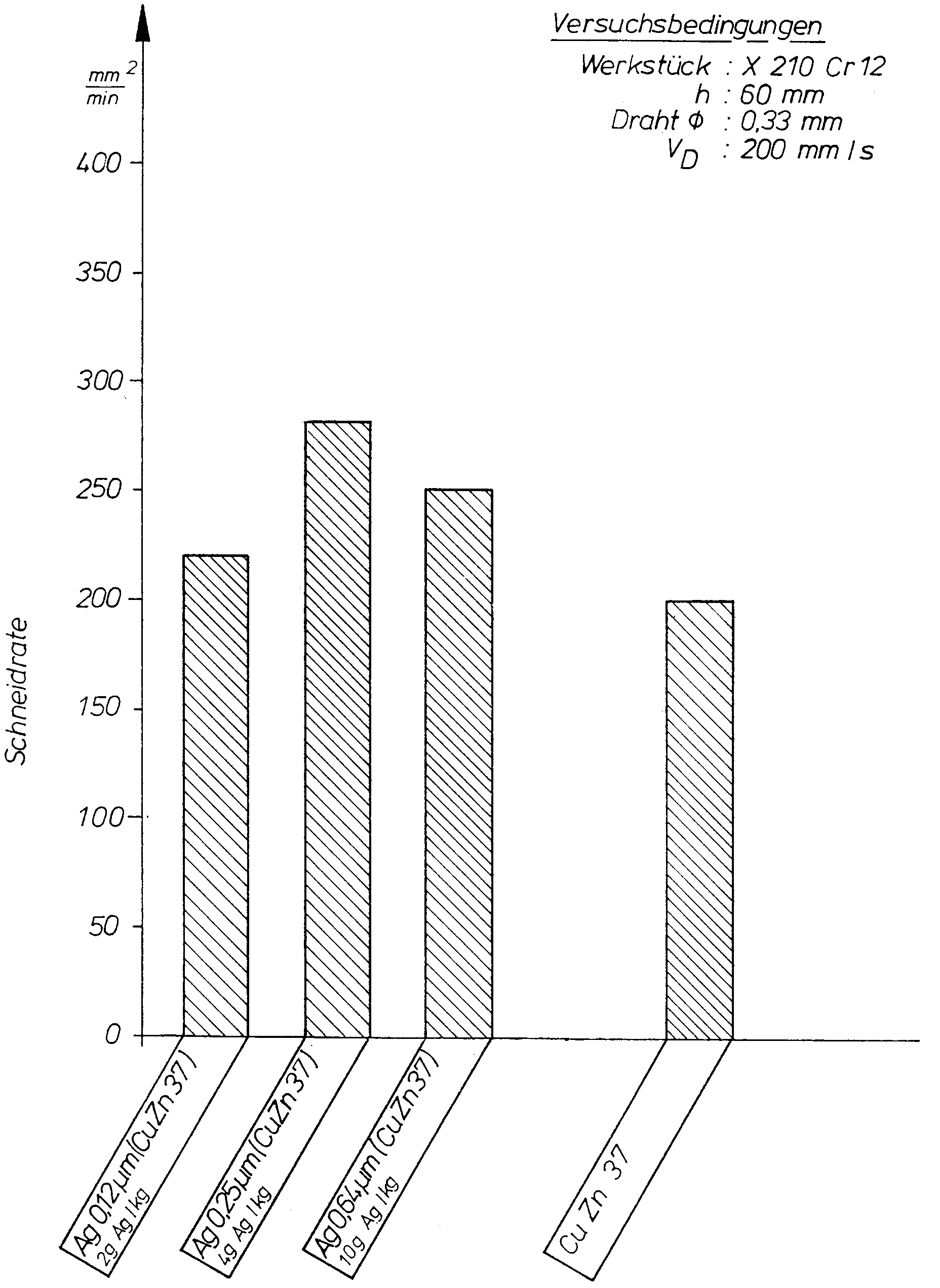
- Die Grafik gibt Meßergebnisse im Vergleich zu einem blanken Messingerodierdraht mit verschiedenen Messing-Erodierdrähten wieder, die in unterschiedlicher Weise mit einer reinen Silberschicht belegt sind. So ist bei Erodierdrähten mit 0,33 mm Durchmesser eine erhebliche Steigerung der Abtragsleistung festzustellen, wenn der Erodierdraht versilbert ist. Die in der Grafik angegebenen Belegungen von 2 bis 10 g/kg Messing ergeben bei diesem Durchmesser eine Silberschicht von 0,12 bis 0,64 µm.
- Die in der Grafik dargestellten Versuche wurden auf modernen Schneidanlagen mit Generatoren von 200 bis 300 kHz durchgeführt. Bei diesen Versuchen zeigte sich, daß die Funkenentladungen präzise und sauber ohne Dämpfung übertragen werden, während nicht überzogene Erodierelektroden dazu neigen, daß die Funkenübertragungen gedämpft werden.
- Desweiteren bewirkt diese hochleitfähige Schicht eine sehr gleichmäßige Erosion, was insbesondere beim Fein- und Präzisschneiden Vorteile bringt. Die hohe Stromdichte entsprechend dem Skin-Effekt bewirkt, daß der Verschleiß der Elektrode gegenüber normalen Elektroden abnimmt. Hierdurch kann beim Fein- und Präzisschneiden die Durchlaufgeschwindigkeit der Drahtelektrode verringert werden (Kostenersparnis), wobei gleichzeitig die Kraterbildung flacher ist, so daß eine geringere Oberflächenrauhheit entsteht. Durch die duktile Schicht des hochleitenden Werkstoffs ist der Gleitwiderstand am Elektrokontakt wesentlich verbessert. Der Verschleiß geht zurück, es gibt wesentlich geringere Vibrationen, und der Draht läuft bei einem präzisen Schnitt ruhig ab.
- Durch die hohe Leitfähigkeit der dünnen Beschichtung hat die Oberfläche eine hohe Kontaktfähigkeit. Hierdurch erreicht man eine präzisere und schnellere Positioniergenauigkeit beim anfänglichen Einstellen und damit eine erhebliche Zeit- und Kostenersparnis. Die abgetragenen Silber-, Goldpartikel, etc. bewirken darüberhinaus eine verbesserte Leitfähigkeit im Schneidkanal, so daß der Funkenübergang gleichfalls verbessert wird. Außerdem wird durch den duktilen Überzug eine Verminderung der Spannungsrißkorrosion des Kernmaterials erreicht. Letztlich verbessert sich damit die Lebensdauer des Elektrodendrahtes.
Claims (4)
- Drahtelektrode zum Schneiden von Werkstücken mittels Funkenerosion, bestehend aus einem Erodierdraht mit oder ohne Ummantelung, wobei zumindest die Ummantelung einen oder mehrere metallische Legierungsbestandteile mit niedriger Verdampfungstemperatur, wie Zink, Kadmium, Blei, Antimon, Wismut, Graphit oder dergleichen enthält, dadurch gekennzeichnet, daß die Drahtelektrode mit einer Deckschicht aus einem elektrisch hochleitfähigem Werkstoff, wie z. B. Silber, Gold, Rhodium, Paladium oder Iridium oder deren Legierungen von ganz geringer Schichtdicke belegt ist.
- Drahtelektrode nach Anspruch 1, dadurch gekennzeichnet, daß die Deckschicht aus Silber besteht.
- Drahtelektrode nach Anspruch 1 und 2, dadurch gekennzeichnet, daß die Deckschicht eine Schichtdicke von 0,05 bis 0,8 µm aufweist.
- Drahtelektrode nach Anspruch 1, dadurch gekennzeichnet, daß die Seele des Erodierdrahtes aus elektrisch gut leitendem Werkstoff, wie Kupfer Kupferseele mit Messing, Messing, (Cu-Zn), Bronze, (Cu-Sn), Stahl mit Cu-Mantel, Wolfram, Molybdän oder dergleichen besteht.
Applications Claiming Priority (2)
| Application Number | Priority Date | Filing Date | Title |
|---|---|---|---|
| DE9013722U DE9013722U1 (de) | 1990-10-02 | 1990-10-02 | Drahtelektrode |
| DE9013722U | 1990-10-02 |
Publications (3)
| Publication Number | Publication Date |
|---|---|
| EP0479007A2 true EP0479007A2 (de) | 1992-04-08 |
| EP0479007A3 EP0479007A3 (en) | 1992-06-03 |
| EP0479007B1 EP0479007B1 (de) | 1993-11-10 |
Family
ID=6857993
Family Applications (1)
| Application Number | Title | Priority Date | Filing Date |
|---|---|---|---|
| EP91115531A Expired - Lifetime EP0479007B1 (de) | 1990-10-02 | 1991-09-13 | Drahtelektrode |
Country Status (16)
| Country | Link |
|---|---|
| US (1) | US5231270A (de) |
| EP (1) | EP0479007B1 (de) |
| JP (1) | JPH04261714A (de) |
| KR (1) | KR100194245B1 (de) |
| CN (1) | CN1029298C (de) |
| AT (1) | ATE97047T1 (de) |
| BR (1) | BR9104229A (de) |
| DE (2) | DE9013722U1 (de) |
| DK (1) | DK0479007T3 (de) |
| ES (1) | ES2045996T3 (de) |
| HK (1) | HK195795A (de) |
| LT (1) | LT3340B (de) |
| LV (1) | LV10752B (de) |
| MX (1) | MX9101383A (de) |
| RU (1) | RU2008148C1 (de) |
| UA (1) | UA25965A1 (de) |
Families Citing this family (15)
| Publication number | Priority date | Publication date | Assignee | Title |
|---|---|---|---|---|
| US6610930B1 (en) | 1998-09-16 | 2003-08-26 | Kulicke & Soffa Investments, Inc. | Composite noble metal wire |
| DE19883017B4 (de) * | 1998-11-13 | 2007-09-27 | Mitsubishi Denki K.K. | Oberflächenbehandlungsverfahren und Elektrode für ein Oberflächenbehandlungsverfahren |
| DE19913694A1 (de) * | 1999-03-25 | 2000-11-02 | Berkenhoff Gmbh | Drahtelektrode |
| ATE238874T1 (de) * | 1999-12-09 | 2003-05-15 | Charmilles Technologies | Drahtelektrode zum funkenerodieren und verfahren zur herstellung |
| JP3884210B2 (ja) * | 2000-03-08 | 2007-02-21 | 尚武 毛利 | ワイヤ電極による加工方法及び装置 |
| MY137479A (en) * | 2000-09-18 | 2009-01-30 | Nippon Steel Corp | Bonding wire for semiconductor device and method for producing the same |
| US6737602B2 (en) | 2002-09-24 | 2004-05-18 | Brian Stelter | EDM apparatus and method incorporating combined electro-erosion and mechanical sawing features |
| US9284647B2 (en) * | 2002-09-24 | 2016-03-15 | Mitsubishi Denki Kabushiki Kaisha | Method for coating sliding surface of high-temperature member, high-temperature member and electrode for electro-discharge surface treatment |
| KR101063575B1 (ko) * | 2002-09-24 | 2011-09-07 | 미츠비시덴키 가부시키가이샤 | 고온부재의 슬라이딩면 코팅 방법 및 고온부재와 방전표면 처리용 전극 |
| CN1692179B (zh) * | 2002-10-09 | 2011-07-13 | 石川岛播磨重工业株式会社 | 回转体及其涂覆方法 |
| JP4943827B2 (ja) * | 2006-11-30 | 2012-05-30 | 矢崎総業株式会社 | 抵抗溶接方法及び導体ユニット |
| RU2466835C2 (ru) * | 2009-11-23 | 2012-11-20 | Государственное образовательное учреждение высшего профессионального образования "Воронежский государственный технический университет" | Способ эрозионно-термической обработки |
| CN102019474B (zh) * | 2010-09-16 | 2012-01-04 | 南京航空航天大学 | 线电极电化学磨削微细工具在线制备系统及方法 |
| EP2808873A1 (de) * | 2013-05-28 | 2014-12-03 | Nexans | Elektrisch leitfähiger Draht und Verfahren zu seiner Herstellung |
| CN103342913B (zh) * | 2013-06-17 | 2015-07-01 | 哈尔滨工业大学 | 用于绝缘陶瓷电火花加工技术的导电涂覆材料及利用其制备辅助电极的方法 |
Family Cites Families (8)
| Publication number | Priority date | Publication date | Assignee | Title |
|---|---|---|---|---|
| GB2015909B (en) | 1978-03-03 | 1982-12-01 | Charmilles Sa Ateliers | Electrode for spark erosion machining |
| JPS5548536A (en) * | 1978-10-04 | 1980-04-07 | Toshiba Corp | Electrode material for electrospark machining |
| SE444278B (sv) * | 1979-10-11 | 1986-04-07 | Charmilles Sa Ateliers | Tradformig elektrod samt sett att tillverka sadan elektrod |
| JPS5715636A (en) * | 1980-07-04 | 1982-01-27 | Masami Kobayashi | Wire-cut electric discharge machining wire |
| JPS6029234A (ja) * | 1983-07-11 | 1985-02-14 | Mitsubishi Electric Corp | ワイヤカツト放電加工用ワイヤ電極 |
| JPS6132872A (ja) * | 1984-07-26 | 1986-02-15 | Fuji Xerox Co Ltd | コロナ放電電極の表面処理方法 |
| EP0312674B1 (de) * | 1987-10-23 | 1992-08-19 | Berkenhoff GmbH | Erodierelektrode, insbesondere Drahtelektrode für die funkenerosive Bearbeitung |
| KR920010862B1 (ko) * | 1988-06-30 | 1992-12-19 | 미쯔비시 덴끼 가부시기가이샤 | 와이어컷방전 가공용 와이어전극 |
-
1990
- 1990-10-02 DE DE9013722U patent/DE9013722U1/de not_active Expired - Lifetime
-
1991
- 1991-09-13 DE DE91115531T patent/DE59100585D1/de not_active Expired - Lifetime
- 1991-09-13 ES ES91115531T patent/ES2045996T3/es not_active Expired - Lifetime
- 1991-09-13 DK DK91115531.5T patent/DK0479007T3/da active
- 1991-09-13 EP EP91115531A patent/EP0479007B1/de not_active Expired - Lifetime
- 1991-09-13 AT AT91115531T patent/ATE97047T1/de not_active IP Right Cessation
- 1991-09-26 US US07/766,634 patent/US5231270A/en not_active Expired - Lifetime
- 1991-09-30 CN CN91109441A patent/CN1029298C/zh not_active Expired - Lifetime
- 1991-10-01 MX MX9101383A patent/MX9101383A/es unknown
- 1991-10-01 UA UA5001593A patent/UA25965A1/uk unknown
- 1991-10-01 KR KR1019910017238A patent/KR100194245B1/ko not_active Expired - Lifetime
- 1991-10-01 BR BR919104229A patent/BR9104229A/pt not_active IP Right Cessation
- 1991-10-01 JP JP3253238A patent/JPH04261714A/ja active Pending
- 1991-10-01 RU SU915001593A patent/RU2008148C1/ru active
-
1993
- 1993-04-20 LV LVP-93-251A patent/LV10752B/lv unknown
- 1993-05-06 LT LTIP515A patent/LT3340B/lt not_active IP Right Cessation
-
1995
- 1995-12-28 HK HK195795A patent/HK195795A/xx not_active IP Right Cessation
Also Published As
| Publication number | Publication date |
|---|---|
| RU2008148C1 (ru) | 1994-02-28 |
| UA25965A1 (uk) | 1999-02-26 |
| US5231270A (en) | 1993-07-27 |
| KR920007729A (ko) | 1992-05-27 |
| DE59100585D1 (de) | 1993-12-16 |
| DE9013722U1 (de) | 1991-01-24 |
| EP0479007A3 (en) | 1992-06-03 |
| HK195795A (en) | 1996-01-05 |
| MX9101383A (es) | 1992-06-05 |
| KR100194245B1 (ko) | 1999-06-15 |
| LT3340B (en) | 1995-07-25 |
| DK0479007T3 (da) | 1994-03-14 |
| LV10752A (lv) | 1995-08-20 |
| CN1029298C (zh) | 1995-07-12 |
| BR9104229A (pt) | 1992-06-02 |
| ES2045996T3 (es) | 1994-01-16 |
| JPH04261714A (ja) | 1992-09-17 |
| LV10752B (en) | 1995-12-20 |
| EP0479007B1 (de) | 1993-11-10 |
| ATE97047T1 (de) | 1993-11-15 |
| CN1060805A (zh) | 1992-05-06 |
| LTIP515A (en) | 1994-11-25 |
Similar Documents
| Publication | Publication Date | Title |
|---|---|---|
| DE2906245C3 (de) | Drahtelektrode für das funkenerosive Schneiden | |
| EP0479007B1 (de) | Drahtelektrode | |
| DE69813840T3 (de) | Drahtelektrode für funkerosionsbearbeitung und verfahren zur herstellung derselben | |
| EP1295664B1 (de) | Drahtelektrode zum funkenerosiven Schneiden | |
| EP0312674B1 (de) | Erodierelektrode, insbesondere Drahtelektrode für die funkenerosive Bearbeitung | |
| DE68903054T2 (de) | Elektrodendraht fuer schneiddrahterosionsmaschine. | |
| DE60206413T2 (de) | Draht für hochgeschwindigkeitsfunkenerosion | |
| DE2604291C3 (de) | Werkstoffanordnung für elektrische Schwachstromkontakte | |
| WO2010063410A1 (de) | Drahtelektrode zum funkenerosiven schneiden | |
| DE69205758T2 (de) | Hochleistungsdrahtelektrode für Funkerosionsbearbeitung und Verfahren zur Herstellung derselben. | |
| EP1038625A2 (de) | Drahtelektrode | |
| WO2010037451A1 (de) | Drahtelektrode zum funkenerosiven schneiden | |
| DE3415054C2 (de) | ||
| EP0232524A2 (de) | Schneiddraht für Elektroentladungsbearbeitung | |
| EP0925138A1 (de) | Hochfeste erodierelektrode | |
| WO2001043909A1 (de) | Elektrode zum elektrochemischen feinbohren von werkstücken sowie verfahren zu ihrer herstellung | |
| DE60032548T2 (de) | Drahtelektrode zum funkenerosiven Schneiden | |
| EP0239879B1 (de) | Stromzuführung für eine drahtförmige Elektrode einer Elektroerosionsmaschine | |
| DE102013009767A1 (de) | Drahtelektrode zum funkenerosiven Schneiden von Gegenständen | |
| DE60105410T2 (de) | Drahtelektrode zum funkenerosiven schneiden | |
| EP0088220B1 (de) | Kontaktelement und Verfahren zu dessen Herstellung | |
| DE3402091A1 (de) | Verbundwerkstoff fuer elektrische kontaktstuecke | |
| DE2028076C3 (de) | Verfahren zur Kontaktierung von Siliziumkarbid-Halbleiterkörpern | |
| DE2607781C3 (de) | Elektrischer Schutzrohrkontakt | |
| DE1948345A1 (de) | Werkstoff fuer elektrische Kontakte |
Legal Events
| Date | Code | Title | Description |
|---|---|---|---|
| PUAI | Public reference made under article 153(3) epc to a published international application that has entered the european phase |
Free format text: ORIGINAL CODE: 0009012 |
|
| AK | Designated contracting states |
Kind code of ref document: A2 Designated state(s): AT BE CH DE DK ES FR GB GR IT LI LU NL SE |
|
| PUAL | Search report despatched |
Free format text: ORIGINAL CODE: 0009013 |
|
| AK | Designated contracting states |
Kind code of ref document: A3 Designated state(s): AT BE CH DE DK ES FR GB GR IT LI LU NL SE |
|
| 17P | Request for examination filed |
Effective date: 19920604 |
|
| 17Q | First examination report despatched |
Effective date: 19921022 |
|
| GRAA | (expected) grant |
Free format text: ORIGINAL CODE: 0009210 |
|
| ITF | It: translation for a ep patent filed | ||
| AK | Designated contracting states |
Kind code of ref document: B1 Designated state(s): AT BE CH DE DK ES FR GB GR IT LI LU NL SE |
|
| REF | Corresponds to: |
Ref document number: 97047 Country of ref document: AT Date of ref document: 19931115 Kind code of ref document: T |
|
| REF | Corresponds to: |
Ref document number: 59100585 Country of ref document: DE Date of ref document: 19931216 |
|
| GBT | Gb: translation of ep patent filed (gb section 77(6)(a)/1977) |
Effective date: 19931207 |
|
| REG | Reference to a national code |
Ref country code: ES Ref legal event code: FG2A Ref document number: 2045996 Country of ref document: ES Kind code of ref document: T3 |
|
| REG | Reference to a national code |
Ref country code: GR Ref legal event code: FG4A Free format text: 3009711 |
|
| ET | Fr: translation filed | ||
| REG | Reference to a national code |
Ref country code: DK Ref legal event code: T3 |
|
| PLBE | No opposition filed within time limit |
Free format text: ORIGINAL CODE: 0009261 |
|
| STAA | Information on the status of an ep patent application or granted ep patent |
Free format text: STATUS: NO OPPOSITION FILED WITHIN TIME LIMIT |
|
| 26N | No opposition filed | ||
| EAL | Se: european patent in force in sweden |
Ref document number: 91115531.5 |
|
| REG | Reference to a national code |
Ref country code: GB Ref legal event code: IF02 |
|
| PGFP | Annual fee paid to national office [announced via postgrant information from national office to epo] |
Ref country code: GR Payment date: 20020912 Year of fee payment: 12 |
|
| PGFP | Annual fee paid to national office [announced via postgrant information from national office to epo] |
Ref country code: SE Payment date: 20020916 Year of fee payment: 12 |
|
| PGFP | Annual fee paid to national office [announced via postgrant information from national office to epo] |
Ref country code: LU Payment date: 20020917 Year of fee payment: 12 |
|
| PGFP | Annual fee paid to national office [announced via postgrant information from national office to epo] |
Ref country code: BE Payment date: 20020918 Year of fee payment: 12 |
|
| PGFP | Annual fee paid to national office [announced via postgrant information from national office to epo] |
Ref country code: DK Payment date: 20020924 Year of fee payment: 12 |
|
| PG25 | Lapsed in a contracting state [announced via postgrant information from national office to epo] |
Ref country code: LU Free format text: LAPSE BECAUSE OF NON-PAYMENT OF DUE FEES Effective date: 20030913 |
|
| PG25 | Lapsed in a contracting state [announced via postgrant information from national office to epo] |
Ref country code: SE Free format text: LAPSE BECAUSE OF NON-PAYMENT OF DUE FEES Effective date: 20030914 |
|
| PG25 | Lapsed in a contracting state [announced via postgrant information from national office to epo] |
Ref country code: DK Free format text: LAPSE BECAUSE OF NON-PAYMENT OF DUE FEES Effective date: 20030930 Ref country code: BE Free format text: LAPSE BECAUSE OF NON-PAYMENT OF DUE FEES Effective date: 20030930 |
|
| BERE | Be: lapsed |
Owner name: *BERKENHOFF G.M.B.H. Effective date: 20030930 |
|
| PG25 | Lapsed in a contracting state [announced via postgrant information from national office to epo] |
Ref country code: GR Free format text: LAPSE BECAUSE OF NON-PAYMENT OF DUE FEES Effective date: 20040402 |
|
| EUG | Se: european patent has lapsed | ||
| REG | Reference to a national code |
Ref country code: DK Ref legal event code: EBP |
|
| PGFP | Annual fee paid to national office [announced via postgrant information from national office to epo] |
Ref country code: ES Payment date: 20100921 Year of fee payment: 20 Ref country code: CH Payment date: 20100923 Year of fee payment: 20 |
|
| PGFP | Annual fee paid to national office [announced via postgrant information from national office to epo] |
Ref country code: IT Payment date: 20100923 Year of fee payment: 20 Ref country code: AT Payment date: 20100920 Year of fee payment: 20 Ref country code: FR Payment date: 20100930 Year of fee payment: 20 |
|
| PGFP | Annual fee paid to national office [announced via postgrant information from national office to epo] |
Ref country code: GB Payment date: 20100924 Year of fee payment: 20 |
|
| PGFP | Annual fee paid to national office [announced via postgrant information from national office to epo] |
Ref country code: NL Payment date: 20100921 Year of fee payment: 20 |
|
| PGFP | Annual fee paid to national office [announced via postgrant information from national office to epo] |
Ref country code: DE Payment date: 20101122 Year of fee payment: 20 |
|
| REG | Reference to a national code |
Ref country code: DE Ref legal event code: R071 Ref document number: 59100585 Country of ref document: DE |
|
| REG | Reference to a national code |
Ref country code: DE Ref legal event code: R071 Ref document number: 59100585 Country of ref document: DE |
|
| REG | Reference to a national code |
Ref country code: NL Ref legal event code: V4 Effective date: 20110913 |
|
| REG | Reference to a national code |
Ref country code: CH Ref legal event code: PL |
|
| REG | Reference to a national code |
Ref country code: GB Ref legal event code: PE20 Expiry date: 20110912 |
|
| PG25 | Lapsed in a contracting state [announced via postgrant information from national office to epo] |
Ref country code: GB Free format text: LAPSE BECAUSE OF EXPIRATION OF PROTECTION Effective date: 20110912 |
|
| PG25 | Lapsed in a contracting state [announced via postgrant information from national office to epo] |
Ref country code: NL Free format text: LAPSE BECAUSE OF EXPIRATION OF PROTECTION Effective date: 20110913 |
|
| PG25 | Lapsed in a contracting state [announced via postgrant information from national office to epo] |
Ref country code: DE Free format text: LAPSE BECAUSE OF EXPIRATION OF PROTECTION Effective date: 20110914 |
|
| REG | Reference to a national code |
Ref country code: ES Ref legal event code: FD2A Effective date: 20130719 |
|
| PG25 | Lapsed in a contracting state [announced via postgrant information from national office to epo] |
Ref country code: ES Free format text: LAPSE BECAUSE OF EXPIRATION OF PROTECTION Effective date: 20110914 |