EP0479323A2 - Extracteur de vecteur de mouvement - Google Patents
Extracteur de vecteur de mouvement Download PDFInfo
- Publication number
- EP0479323A2 EP0479323A2 EP19910116998 EP91116998A EP0479323A2 EP 0479323 A2 EP0479323 A2 EP 0479323A2 EP 19910116998 EP19910116998 EP 19910116998 EP 91116998 A EP91116998 A EP 91116998A EP 0479323 A2 EP0479323 A2 EP 0479323A2
- Authority
- EP
- European Patent Office
- Prior art keywords
- moving vector
- vector extractor
- difference
- extractor
- value
- Prior art date
- Legal status (The legal status is an assumption and is not a legal conclusion. Google has not performed a legal analysis and makes no representation as to the accuracy of the status listed.)
- Withdrawn
Links
Images


Classifications
-
- G—PHYSICS
- G06—COMPUTING OR CALCULATING; COUNTING
- G06T—IMAGE DATA PROCESSING OR GENERATION, IN GENERAL
- G06T7/00—Image analysis
- G06T7/20—Analysis of motion
- G06T7/223—Analysis of motion using block-matching
-
- G—PHYSICS
- G06—COMPUTING OR CALCULATING; COUNTING
- G06T—IMAGE DATA PROCESSING OR GENERATION, IN GENERAL
- G06T7/00—Image analysis
- G06T7/20—Analysis of motion
- G06T7/254—Analysis of motion involving subtraction of images
-
- H—ELECTRICITY
- H04—ELECTRIC COMMUNICATION TECHNIQUE
- H04N—PICTORIAL COMMUNICATION, e.g. TELEVISION
- H04N23/00—Cameras or camera modules comprising electronic image sensors; Control thereof
- H04N23/60—Control of cameras or camera modules
- H04N23/68—Control of cameras or camera modules for stable pick-up of the scene, e.g. compensating for camera body vibrations
-
- H—ELECTRICITY
- H04—ELECTRIC COMMUNICATION TECHNIQUE
- H04N—PICTORIAL COMMUNICATION, e.g. TELEVISION
- H04N23/00—Cameras or camera modules comprising electronic image sensors; Control thereof
- H04N23/60—Control of cameras or camera modules
- H04N23/68—Control of cameras or camera modules for stable pick-up of the scene, e.g. compensating for camera body vibrations
- H04N23/681—Motion detection
- H04N23/6811—Motion detection based on the image signal
-
- H—ELECTRICITY
- H04—ELECTRIC COMMUNICATION TECHNIQUE
- H04N—PICTORIAL COMMUNICATION, e.g. TELEVISION
- H04N23/00—Cameras or camera modules comprising electronic image sensors; Control thereof
- H04N23/60—Control of cameras or camera modules
- H04N23/68—Control of cameras or camera modules for stable pick-up of the scene, e.g. compensating for camera body vibrations
- H04N23/682—Vibration or motion blur correction
-
- H—ELECTRICITY
- H04—ELECTRIC COMMUNICATION TECHNIQUE
- H04N—PICTORIAL COMMUNICATION, e.g. TELEVISION
- H04N23/00—Cameras or camera modules comprising electronic image sensors; Control thereof
- H04N23/60—Control of cameras or camera modules
- H04N23/68—Control of cameras or camera modules for stable pick-up of the scene, e.g. compensating for camera body vibrations
- H04N23/682—Vibration or motion blur correction
- H04N23/685—Vibration or motion blur correction performed by mechanical compensation
- H04N23/687—Vibration or motion blur correction performed by mechanical compensation by shifting the lens or sensor position
-
- G—PHYSICS
- G06—COMPUTING OR CALCULATING; COUNTING
- G06T—IMAGE DATA PROCESSING OR GENERATION, IN GENERAL
- G06T2207/00—Indexing scheme for image analysis or image enhancement
- G06T2207/10—Image acquisition modality
- G06T2207/10016—Video; Image sequence
Definitions
- This invention is related to the extraction technology of moving vector from an image signal for preventing VTR with a camera incorporated therein from shaking.
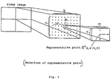
- This representative point matching method will be explained in a case a given frame image is divided into four blocks as shown in Fig. 2 and a moving vector of one of those blocks is calculated.
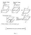
- Fig. 3 describes the concept.
- a data for the absolute value of the difference including a curved line K whose value is 0 will be obtained, then by accumulating this data for the absolute value of the difference for each representative point, the accumulated value at the intersection of the curved line K will be the minimum value, and this is the position of the moving vector.
- the accumulation function p(i, j) will be a funnel-like concavity centering the moving vector position (i, j).
- accumulation memory needs to have multi-bit capacity for calculating the sum of the absolute value of the difference between frames in order to store the sum of multi-value, then the accumulation memory will have a lot of capacity. For example, when one moving vector is extracted, assuming the absolute value of the difference value corresponding to one representative point to be a bit, a searching area to be m pixel ⁇ n pixel and the accumulated time, i.e. the number of representative points to be p, the accumulation memory will need to be (a + ⁇ p) m ⁇ n bit .
- the object of the present invention is to reduce the capacity of accumulation memory, and to make the scale of hardware small, with maintaining the precision of moving vector extraction.
- a moving vector extractor is characterized by operation of binarization after operation of multi-value correlation and extraction of a displacement value that has the minimum or maximum value of the accumulated value of a binarized as a moving vector.
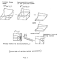
- an absolute value or squared value is calculated of the difference between successive frames with predetermined time distance, and it is transformed into a line as candidates of moving vector through binarization as shown in Fig. 1, and the accumulated value for the concerned pixels of number of P is calculated, and the position that has the maximum or minimum value is calculated.
- This position is the cross point of candidate lines of moving vector and a moving vector will be extracted based on this position.
- the capacity necessary for the accumulation memory becomes (1 + ⁇ p) ⁇ m ⁇ n and can be reduced to (1 + ⁇ p) / (a + ⁇ p) compared to the conventional method.
- Fig. 1 shows a principle of the present invention.
- Fig. 2 shows the position of a representative point.
- Fig. 3 shows a concept of representative point matching method.
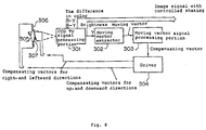
- Fig. 4 shows a block diagram of the first embodiment of the present invention.
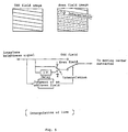
- Fig. 5 shows a concept of interpolation of line in a field image.
- Fig. 6 shows a block diagram of the second embodiment of the present invention.
- Fig. 7 shows a block diagram of the third embodiment of the present invention.
- Fig. 8 shows a block diagram of the forth embodiment of the present invention.
- Fig. 1 shows the principle of the present invention
- Fig. 2 is a descriptive drawing showing a position of representative point
- Fig. 4 is a block diagram of the first embodiment.
- representative points aligned on b columns in the horizontal direction and on c lines in the vertical direction are selected, so that a rectangle block is defined by each representative point centered in the block.
- the block is a searching area of m pixels in the horizontal direction and n pixels in the vertical direction.
- the brightness of each representative point in the previous frame is stored in a memory.
- the brightness of representative point on dth column and eth row is denoted here as a n-1 d,e (0, 0).
- This absolute value of the difference value is binarized by a threshold A. It means when
- ⁇ A, p d,e (i, j) 0 when
- ⁇ A, p d,e (i, j) 1 (2)
- a basic data of moving vector can be obtained for each representative point, and this basic data of moving vector has one candidate curved line of moving vector.
- the basic data of moving vector of total representative points of b rows ⁇ c columns are added in an accumulation memory, then an address (i, j) of the minimum of the accumulated value.
- the address (i, j) gives a moving vector.
- moving vector (i, j)
- p(i, j) min (4)
- an input terminal 10, to which image signal is given is connected with a + input terminal of a subtracter 21 through an A/D convertor 11, low band pass filter 12 to reduce influence from noise, and high band pass filter to reduce influence from the change of brightness over the whole image.
- Output from high pass filter 13 is connected with - input terminal of subtracter 21 through representative memory 18 and 19, and the data of the representative memory will be transferred to memory 19 after registration in memory 18.
- Subtracter 21 and absolute value calculator 22 are provided for calculating correlation between two frames, and the absolute value calculator 22 is connected with comparator 26 for binarization.
- Adder 23 which accumulates and adds the binarized data is connected with comparator 23, and accumulation memory 24 is connected with adder 23.
- Extractor 25 is connected with accumulation memory 24 for extracting moving vector.
- Timing generator 20 counts clocks CK, horizontal synchronous signals and vertical synchronous signals that are inputted from outside, so as to generate control signals for such as A/D convertor 11, representative memory 18 and 19, accumulation memory 24 and extractor 25.
- analog image signals inputted from image input terminal 10 are quantized into 8 bits in A/D convertor 11, and unnecessary noises are temporally removed by low pass filter 12 and high pass filter 13, and outputted as brightness a n d,e (i, j).
- Image signals whose noises are removed are stored in representative memory 18 as representative point a n d,e (0, 0) of current frame at the timing generated by timing generator 20.
- the brightness of this representative point is transferred to representative memory 19 during the next vertical synchronous term, and outputted to subtracter 21 as representative point a n-1 d,e (0, 0) of previous frame.
- addressing of representative memory 18 and 19, and read/write indication are operated by timing generator 21.
- Output signal from absolute value system 22 is added to comparator 26, and binarized by threshold A using the above formula (2), and accumulated and added to accumulation memory 24 by adder 23.
- the moving vector is extracted from the difference between two successive frame images, and the two frame images mean a combination of a previous odd field image and a current odd field image, or a combination of a previous even field image and a current even field image.
- successive field images may also be used.
- a moving vector is extracted from the difference between an odd field image and an even field image, or between an even field image and an odd field image. Since each field line of one of even and odd field image displaces from the field line of the other by a half of distance between successive field lines, interpolated lines between successive field lines are to be generated in one of odd or even field.
- Fig. 6 describes the second embodiment of the present invention, and this is a compensation system for shaking of VTR with a camera incorporated therein which uses a moving vector extractor explained in the above first embodiment.
- 101 represents a CCD TV signal processing portion
- 102 is a moving vector extractor
- 103 is a field memory or frame memory for storing an image of the previous field or frame
- 104 represents a moving vector signal processing portion which judges the reliability of a band filter for determining compensation frequency and of moving vector extraction
- 105 represents an interpolating enlargement processing portion which enlarges a part of an image with interpolation stored in a field memory or a frame memory.
- a brightness signal outputted from CCD TV signal processing portion 101 is inputted into moving vector extractor 102, and a moving vector is extracted from image signal of two successive fields or a frames.
- the brightness signal and a signal of color difference R-Y and B-Y outputted from CCD TV signal processing portion 101 are stored in a field or frame memory 103, and are partially enlarged in interpolating enlargement processing portion 105 after the delay of one field or one frame.
- the moving vector extracted by moving vector extractor 102 is inputted into a control terminal of interpolating enlargement processing portion 105 through moving vector signal processing portion 104, and it is compensated for the amount of the extracted moving vectors that are elements of shaking, in upper and lower, right and left sides by interpolating enlargement processing portion 105 , and TV image signal, in which the shaking is controlled, is obtained.
- Fig. 7 shows the third embodiment of the present invention, and this is a compensation system for shaking of VTR with a camera incorporated therein, which uses a moving vector extractor explained in the above first embodiment.
- CCD TV signal processing portion 201 controls the number of high speed output clocks accompanying vertical electric change translation , so the movement of an image upward, downward, rightward or leftward is also controllable by controllable delay 202.
- Brightness signal of an image outputted from CCD TV signal processing portion 201 is inputted into moving vector extractor 203 through controllable delay line 202, and a moving vector is extracted from image signal as well as in the operation of the second embodiment.
- the moving vector extracted is inputted into moving vector processing portion 204 and processing is performed there, in which the reliability is judged of a band filter for determining compensation frequency and of moving vector extraction.
- the compensating vectors for upward and downward directions are fed back to CCD TV signal processing portion 201, and compensating vectors for rightward and leftward directions are fed back to controllable delay line 202, and shaking is compensated through closed loop servo.
- Fig. 8 shows the third embodiment of the present invention, and this is a compensation system for the shaking of VTR with a camera incorporated therein, including a moving vector extractor explained in the above first embodiment.
- 301 represents CCD TV signal processing portion
- 302 is a moving vector extractor, and a moving vector is extracted similarly to the operation of the second embodiment.
- the extracted moving vector is inputted into moving vector processing portion 303 and processing is preformed, in which it is judged the reliability of a band filter for determining compensation frequency and of moving vector extraction.
- Lens 305 is supported by actuators 306 and 307 so as to be movable in two dimensions perpendicular to the optical axis of the lens. It means lens 305 is moved in two dimensions by impressing compensation voltage to the actuators.
- Compensating vector outputted from moving vector signal processing portion 303 is amplified in driver 304 in the directions of up, down, right and leftward, and by impressing compensation voltage to actuator 306 and 307, the position of lens 305 is compensated.
- a feed-back loop for compensating movement of an image is constructed.
- the receptor of CCD should be driven together with the lens.
- an absolute value of the difference between frames is calculated. It is also possible to calculate squared value of the difference value for obtaining the moving vector.
- the present invention has advantages that the result of multi-value correlation is binarized to be accumulated, so the hardware for extracting moving vector is smaller in size due to its simplicity calculation as well as small memory size, than a system accumulating multi-value data.
- moving extracting system for compensating shaking of VTR with a camera incorporated therein.
Landscapes
- Engineering & Computer Science (AREA)
- Multimedia (AREA)
- Signal Processing (AREA)
- Computer Vision & Pattern Recognition (AREA)
- Physics & Mathematics (AREA)
- General Physics & Mathematics (AREA)
- Theoretical Computer Science (AREA)
- Resistance Heating (AREA)
- Image Analysis (AREA)
- Compression Or Coding Systems Of Tv Signals (AREA)
Applications Claiming Priority (2)
| Application Number | Priority Date | Filing Date | Title |
|---|---|---|---|
| JP2269255A JPH04145777A (ja) | 1990-10-05 | 1990-10-05 | 動きベクトル検出装置 |
| JP269255/90 | 1990-10-05 |
Publications (2)
| Publication Number | Publication Date |
|---|---|
| EP0479323A2 true EP0479323A2 (fr) | 1992-04-08 |
| EP0479323A3 EP0479323A3 (fr) | 1994-02-16 |
Family
ID=17469809
Family Applications (1)
| Application Number | Title | Priority Date | Filing Date |
|---|---|---|---|
| EP19910116998 Withdrawn EP0479323A2 (fr) | 1990-10-05 | 1991-10-04 | Extracteur de vecteur de mouvement |
Country Status (3)
| Country | Link |
|---|---|
| EP (1) | EP0479323A2 (fr) |
| JP (1) | JPH04145777A (fr) |
| KR (1) | KR940006308B1 (fr) |
Families Citing this family (4)
| Publication number | Priority date | Publication date | Assignee | Title |
|---|---|---|---|---|
| JPH04196983A (ja) * | 1990-11-28 | 1992-07-16 | Mitsubishi Electric Corp | 動き検出装置 |
| US5767898A (en) * | 1994-06-23 | 1998-06-16 | Sanyo Electric Co., Ltd. | Three-dimensional image coding by merger of left and right images |
| US5963673A (en) * | 1995-12-20 | 1999-10-05 | Sanyo Electric Co., Ltd. | Method and apparatus for adaptively selecting a coding mode for video encoding |
| US6380967B1 (en) * | 1996-12-07 | 2002-04-30 | Frank Sacca | System to capture, store, and retrieve composite video for transmission over telephone lines |
Family Cites Families (3)
| Publication number | Priority date | Publication date | Assignee | Title |
|---|---|---|---|---|
| KR910009880B1 (ko) * | 1983-07-25 | 1991-12-03 | 가부시기가이샤 히다찌세이사꾸쇼 | 인터레이스된 텔레비젼 신호중의 화상의 움직임 검출회로 |
| JPS60264188A (ja) * | 1984-06-13 | 1985-12-27 | Victor Co Of Japan Ltd | 画像の動き検出装置 |
| JPH01106582A (ja) * | 1987-10-19 | 1989-04-24 | Nec Home Electron Ltd | 撮像装置 |
-
1990
- 1990-10-05 JP JP2269255A patent/JPH04145777A/ja active Pending
-
1991
- 1991-10-04 EP EP19910116998 patent/EP0479323A2/fr not_active Withdrawn
- 1991-10-04 KR KR1019910017422A patent/KR940006308B1/ko not_active Expired - Lifetime
Also Published As
| Publication number | Publication date |
|---|---|
| JPH04145777A (ja) | 1992-05-19 |
| EP0479323A3 (fr) | 1994-02-16 |
| KR920009190A (ko) | 1992-05-28 |
| KR940006308B1 (ko) | 1994-07-14 |
Similar Documents
| Publication | Publication Date | Title |
|---|---|---|
| RU2117412C1 (ru) | Способ и устройство для сравнения сигнала изображения между соседними кадрами и оценки движения изображений | |
| US6819778B2 (en) | Method and system for tracking a fast moving object | |
| EP0181215B1 (fr) | Dispositif de détection du mouvement d'images de télévision | |
| US6005609A (en) | Method and apparatus for digital correlation object tracker using a shape extraction focalization technique | |
| US5408269A (en) | Moving picture encoding apparatus and method | |
| EP0679034B1 (fr) | Appareil et méthode pour détecter des vecteurs de mouvement | |
| JPH0787495A (ja) | 動きベクトル検出装置および方法 | |
| US6590937B1 (en) | Efficient motion vector detection | |
| EP0481421B1 (fr) | Extracteur de vecteur de mouvement | |
| US6122319A (en) | Motion compensating apparatus using gradient pattern matching and method thereof | |
| US6266371B1 (en) | Motion vector detecting apparatus and method | |
| JP3123130B2 (ja) | 動きベクトル検出装置 | |
| US5475446A (en) | Picture signal motion detector employing partial decimation of pixel blocks | |
| EP0479323A2 (fr) | Extracteur de vecteur de mouvement | |
| EP0450889A2 (fr) | Correction du décalage d'images pour une caméra vidéo | |
| US5943450A (en) | Apparatus and method for compensating for camera vibration during video photography | |
| JP2930675B2 (ja) | 初期偏位ベクトルを用いた動きベクトルの検出方法 | |
| JP3192698B2 (ja) | 動きベクトル評価装置 | |
| EP0479324B1 (fr) | Caméra incorporant des fonctions de détection et de correction des tremblements d'images | |
| WO1999017256A3 (fr) | Procede de determination de vecteurs blocs destine a l'evaluat ion de mouvements | |
| JP2693515B2 (ja) | 画像動き検出装置 | |
| JP2614574B2 (ja) | 動きベクトル検出回路 | |
| JP3528115B2 (ja) | 動き予測ベクトル検出回路 | |
| JPH0818974A (ja) | 動画像符号化装置および動画像の動き検出装置 | |
| JP2735264B2 (ja) | 動き補正撮像装置 |
Legal Events
| Date | Code | Title | Description |
|---|---|---|---|
| PUAI | Public reference made under article 153(3) epc to a published international application that has entered the european phase |
Free format text: ORIGINAL CODE: 0009012 |
|
| AK | Designated contracting states |
Kind code of ref document: A2 Designated state(s): DE FR GB |
|
| RAP1 | Party data changed (applicant data changed or rights of an application transferred) |
Owner name: EZEL INC. Owner name: SHARP CORPORATION |
|
| PUAL | Search report despatched |
Free format text: ORIGINAL CODE: 0009013 |
|
| RAP3 | Party data changed (applicant data changed or rights of an application transferred) |
Owner name: SHARP CORPORATION Owner name: EZEL INC. |
|
| AK | Designated contracting states |
Kind code of ref document: A3 Designated state(s): DE FR GB |
|
| 17P | Request for examination filed |
Effective date: 19940427 |
|
| STAA | Information on the status of an ep patent application or granted ep patent |
Free format text: STATUS: THE APPLICATION IS DEEMED TO BE WITHDRAWN |
|
| 18D | Application deemed to be withdrawn |
Effective date: 19960501 |