EP0479344B1 - Arbeitssystem für Innenwände der Wasserkammern in dem Dampferzeuger eines Kernreaktors - Google Patents
Arbeitssystem für Innenwände der Wasserkammern in dem Dampferzeuger eines Kernreaktors Download PDFInfo
- Publication number
- EP0479344B1 EP0479344B1 EP91122369A EP91122369A EP0479344B1 EP 0479344 B1 EP0479344 B1 EP 0479344B1 EP 91122369 A EP91122369 A EP 91122369A EP 91122369 A EP91122369 A EP 91122369A EP 0479344 B1 EP0479344 B1 EP 0479344B1
- Authority
- EP
- European Patent Office
- Prior art keywords
- arm
- steam generator
- vehicle
- suction cup
- hinge
- Prior art date
- Legal status (The legal status is an assumption and is not a legal conclusion. Google has not performed a legal analysis and makes no representation as to the accuracy of the status listed.)
- Expired - Lifetime
Links
- XLYOFNOQVPJJNP-UHFFFAOYSA-N water Substances O XLYOFNOQVPJJNP-UHFFFAOYSA-N 0.000 claims abstract description 38
- 238000005202 decontamination Methods 0.000 claims abstract description 29
- 230000003588 decontaminative effect Effects 0.000 claims abstract description 27
- 239000003792 electrolyte Substances 0.000 claims description 10
- 238000006073 displacement reaction Methods 0.000 claims description 5
- 238000005192 partition Methods 0.000 claims description 4
- 238000013519 translation Methods 0.000 claims description 2
- 238000005498 polishing Methods 0.000 claims 1
- 238000010586 diagram Methods 0.000 description 3
- 239000004743 Polypropylene Substances 0.000 description 2
- 230000000694 effects Effects 0.000 description 2
- 239000012530 fluid Substances 0.000 description 2
- -1 polytetrafluoroethylene Polymers 0.000 description 2
- 239000000725 suspension Substances 0.000 description 2
- 235000004443 Ricinus communis Nutrition 0.000 description 1
- 240000000528 Ricinus communis Species 0.000 description 1
- 241001080024 Telles Species 0.000 description 1
- 238000005452 bending Methods 0.000 description 1
- 230000005540 biological transmission Effects 0.000 description 1
- 230000015572 biosynthetic process Effects 0.000 description 1
- 230000015556 catabolic process Effects 0.000 description 1
- 244000145845 chattering Species 0.000 description 1
- 238000011109 contamination Methods 0.000 description 1
- 238000001816 cooling Methods 0.000 description 1
- 238000012937 correction Methods 0.000 description 1
- 238000013461 design Methods 0.000 description 1
- 238000000605 extraction Methods 0.000 description 1
- 238000010438 heat treatment Methods 0.000 description 1
- 238000009434 installation Methods 0.000 description 1
- 239000000463 material Substances 0.000 description 1
- 238000012544 monitoring process Methods 0.000 description 1
- 229920001155 polypropylene Polymers 0.000 description 1
- 229920001343 polytetrafluoroethylene Polymers 0.000 description 1
- 239000004810 polytetrafluoroethylene Substances 0.000 description 1
- 238000003825 pressing Methods 0.000 description 1
- 230000005855 radiation Effects 0.000 description 1
- 239000000941 radioactive substance Substances 0.000 description 1
- 238000007789 sealing Methods 0.000 description 1
- 229920002994 synthetic fiber Polymers 0.000 description 1
- 229920002554 vinyl polymer Polymers 0.000 description 1
- 238000003466 welding Methods 0.000 description 1
Images



Classifications
-
- G—PHYSICS
- G21—NUCLEAR PHYSICS; NUCLEAR ENGINEERING
- G21F—PROTECTION AGAINST X-RADIATION, GAMMA RADIATION, CORPUSCULAR RADIATION OR PARTICLE BOMBARDMENT; TREATING RADIOACTIVELY CONTAMINATED MATERIAL; DECONTAMINATION ARRANGEMENTS THEREFOR
- G21F9/00—Treating radioactively contaminated material; Decontamination arrangements therefor
-
- G—PHYSICS
- G21—NUCLEAR PHYSICS; NUCLEAR ENGINEERING
- G21F—PROTECTION AGAINST X-RADIATION, GAMMA RADIATION, CORPUSCULAR RADIATION OR PARTICLE BOMBARDMENT; TREATING RADIOACTIVELY CONTAMINATED MATERIAL; DECONTAMINATION ARRANGEMENTS THEREFOR
- G21F9/00—Treating radioactively contaminated material; Decontamination arrangements therefor
- G21F9/001—Decontamination of contaminated objects, apparatus, clothes, food; Preventing contamination thereof
-
- F—MECHANICAL ENGINEERING; LIGHTING; HEATING; WEAPONS; BLASTING
- F22—STEAM GENERATION
- F22B—METHODS OF STEAM GENERATION; STEAM BOILERS
- F22B37/00—Component parts or details of steam boilers
- F22B37/002—Component parts or details of steam boilers specially adapted for nuclear steam generators, e.g. maintenance, repairing or inspecting equipment not otherwise provided for
- F22B37/003—Maintenance, repairing or inspecting equipment positioned in or via the headers
-
- G—PHYSICS
- G21—NUCLEAR PHYSICS; NUCLEAR ENGINEERING
- G21F—PROTECTION AGAINST X-RADIATION, GAMMA RADIATION, CORPUSCULAR RADIATION OR PARTICLE BOMBARDMENT; TREATING RADIOACTIVELY CONTAMINATED MATERIAL; DECONTAMINATION ARRANGEMENTS THEREFOR
- G21F9/00—Treating radioactively contaminated material; Decontamination arrangements therefor
- G21F9/001—Decontamination of contaminated objects, apparatus, clothes, food; Preventing contamination thereof
- G21F9/002—Decontamination of the surface of objects with chemical or electrochemical processes
- G21F9/004—Decontamination of the surface of objects with chemical or electrochemical processes of metallic surfaces
Definitions
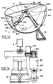
- the deflection plane of the hinge 1200 constitutes in operation, the first element denoted 1 and the second element denoted 2 forming an arm being in the deployed position, a diametral plane of the hemispherical bowl of the BAE water box of the steam generator.
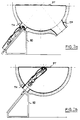
- FIG. 2a the system which is the subject of the invention is implemented by means of an elevator 50 as previously described.
- the system is slid by translation on the inclined plane of the elevator and the contact plate is brought in the vicinity of the tubular plate, in order to ensure the fixing thereon.
- the system thus fixed both on the tubular plate PT and on the flange of the manhole TH is shown in FIG. 2b.
- the formation of the positioning position of the support plate on the tube plate is given for example by three proximity detectors arranged on the support plate for this purpose.
- Figures 2d and 2e provide a better understanding of the principle of monitoring the arm 2 during its movement in the hemispherical bowl of the water box BAE of the steam generator.
- the pusher arm 2 by means of the jack 2000, applies the vehicle 3 against the spherical surface of the water box and follows the movements of the vehicle 3 thanks to the two degrees of freedom present at l hinge 1200.
- a set of rollers 305 is integral with the suction cup body 300, the rollers being intended to form abutment for supporting the suction cup on the surface S in order to keep the distance from l electrode 301 at the surface S to be treated.
- the seal 304 Under the effect of the vacuum induced by the suction of the electrolyte, the seal 304 is normally crushed.
- the aforementioned set of rollers constituted by castors made of polytetrafluoroethylene for example, is mounted on ball bearings with pivoting axis fixed on the body of the suction cup. This set of rollers has the function of ensuring and facilitating the sliding of the suction cup on the surface S, and prevents the chattering phenomenon which appears when the seal 304 is too crushed.
Landscapes
- Engineering & Computer Science (AREA)
- Physics & Mathematics (AREA)
- General Engineering & Computer Science (AREA)
- High Energy & Nuclear Physics (AREA)
- Life Sciences & Earth Sciences (AREA)
- Food Science & Technology (AREA)
- Electrochemistry (AREA)
- Chemical Kinetics & Catalysis (AREA)
- Chemical & Material Sciences (AREA)
- General Chemical & Material Sciences (AREA)
- Thermal Sciences (AREA)
- Mechanical Engineering (AREA)
- Manipulator (AREA)
- Structure Of Emergency Protection For Nuclear Reactors (AREA)
- Other Liquid Machine Or Engine Such As Wave Power Use (AREA)
- Domestic Plumbing Installations (AREA)
- Cleaning In General (AREA)
Claims (8)
- Arbeitssystem für den Wasserkasten der Dampferzeuger eines Kernkraftwerks, welches umfaßt:- ein erstes Element (1) mit einer im wesentlichen länglichen Form, welches einen ersten Arm des Systems bildet,- ein zweites Element (2) mit einer im wesentlichen länglichen Form, welches an einem seiner Enden an einem Ende des ersten Elements angelenkt ist, wobei das zweite Element (2) einen zweiten Arm des Systems bildet und die Einheit aus erstem (1) und zweitem (2) Arm in den Wasserkasten (BAE) des Dampferzeugers (GV) über eine Einstiegsöffnung (TH) eingeführt werden kann und das zweite Element (2) in eine ausgefahrene Position bezüglich des ersten Elements (1) gebracht werden kann,- einen Wagen (3), welcher an dem zweiten Arm (2) montiert ist, wobei dieser Wagen (3) bezüglich des zweiten Arms (2) beweglich montiert ist,- eine Arbeitseinrichtung (30), welche von dem Wagen (3) getragen wird, wobei die Arbeitseinrichtung (30) aufgrund ihrer Bewegung bezüglich des zweiten Arms und der relativen Öffnung zwischen dem ersten (1) und dem zweiten (2) Arm in der Lage ist, mehrere Bereiche der inneren Oberfläche des Dampferzeugers zu erreichen, wie die primären Rohrleitungen (TP), die Trennplatte (PP), die innere Wand der sphärischen Schale des Wasserkastens (BAE) des Dampferzeugers,
dadurch gekennzeichnet, daß zum Gewährleisten einer Maßnahme wie der Dekontamination der inneren Wände der sphärischen Schale des Wasserkastens (BAE) eines Dampferzeugers das den zweiten Arm bildende zweite Element (2) an dem ersten Arm über ein an einer Rohrplatte (PT) des Dampferzeugers befestigtes Drehgelenk (1200) angelenkt ist, dessen Auslenkungsebene durch Drehung orientierbar ist, wobei diese Ebene, welche durch die Längsachse (Δ′) des zweiten Arms und die Drehachse für die Orientierung (D3) gebildet wird, im Betrieb eine diametrische Ebene bezüglich der halbkugelförmigen Schale darstellt, und daß das orientierbare Drehgelenk (1200) umfaßt:- ein Lager (12000), welches am Ende des ersten Arms (1) befestigt ist und mit einer Platte zum Kontakt mit der Rohrplatte (PT) des Dampferzeugers versehen ist,- einen Drehteller (12001), der frei um das Lager drehbar ist und dessen Drehachse die Drehachse für die Orientierung (D3) der Auslenkungsebene des orientierbaren Drehgelenks (1200) bildet, wobei dieser Drehteller (12001) an seinem Rand ein Gelenk (12002) mit einer zu der Drehachse für die Rotation (D3) orthogonalen Achse (D4) umfaßt und ein orientierbares Drehgelenk bildet, wobei der zweite Arm (2) um das genannte Gelenk (12002) schwenkbar gelagert ist. - System nach Anspruch 1, dadurch gekennzeichnet, daß der Wagen (3) am Ende des zweiten Arms (2) über ein Schubelement (2000) montiert ist, welches im Betrieb das Ansetzen des Wagens (3) an die innere Wand der halbkugelförmigen Schale des Wasserkastens des Dampferzeugers gestattet.
- System nach Anspruch 2, dadurch gekennzeichnet, daß der Wagen (3) weiterhin bezüglich der Längsachse des zweiten Arms über eine Getriebemotorgruppe (2001) drehbar beweglich ist.
- System nach Anspruch 3, dadurch gekennzeichnet, daß der Wagen (3) mit einem Fortbewegungssystem versehen ist, welches aus mehreren motorgetriebenen Antriebsrollen (331, 332, 333) besteht.
- System nach Anspruch 4, dadurch gekennzeichnet, daß die Rollen (331, 332, 333) ein Dreibeinsystem bilden, wobei die Antriebssteuerung jeder Rolle unabhängig ist.
- System nach einem der Ansprüche 1 bis 5, dadurch gekennzeichnet, daß zum Gewährleisten des Einführens und des Positionierens der durch den ersten (1) und den zweiten (2) Arm gebildeten Einheit in dem Einstiegsloch (TH) das System weiterhin ein Hubsystem (50) mit einer geneigten Ebene umfaßt, wobei der Neigungswinkel der geneigten Ebene es mit einer alleinigen Translation der Einheit gestattet, das Gelenk (1200) des ersten und zweiten Arms in der Nähe des Zentrums der Rohrplatte (PT) des Dampferzeugers zu positionieren.
- System nach einem der Ansprüche 1 bis 6, dadurch gekennzeichnet, daß die Arbeitseinrichtung (30) eine Elektropolierzelle umfaßt.
- System nach Anspruch 7, dadurch gekennzeichnet, daß die Zelle (30) umfaßt:- ein Saugelement, welches von einem im wesentlichen rotationssymmetrischen Saugkörper (300) gebildet wird,- eine permeable Elektrode (301), welche sich in dem Saugkörper (300) befindet und in diesem eine Elektrolyt-Einlaßkammer (302) und eine Elektrolyt-Ansaugkammer (303) begrenzt, wenn der Saugkörper an die Wand der zu behandelnden Oberfläche angesetzt wird,- eine Dichtung (304), welche am Rand des Saugkörpers angeordnet ist,- einen Satz von an dem Saugkörper (300) ausgebildeten Rollen (305), wobei diese Rollen dafür vorgesehen sind, einen Anschlag beim Ansetzen des Saugelements an die Oberfläche zu bilden, um den Abstand zwischen der Elektrode und der zu behandelnden Oberfläche konstant zu halten.
Applications Claiming Priority (3)
| Application Number | Priority Date | Filing Date | Title |
|---|---|---|---|
| FR8700994 | 1987-01-28 | ||
| FR8700994A FR2610137B1 (fr) | 1987-01-28 | 1987-01-28 | Systeme de decontamination des tuyauteries primaires et de la boite a eau d'un generateur de vapeur de centrale nucleaire |
| EP88400163A EP0281433B1 (de) | 1987-01-28 | 1988-01-26 | Arbeitssystem für primäre Rohrleitungen und Wasserkammer des Dampferzeugers eines Kernreaktors |
Related Parent Applications (1)
| Application Number | Title | Priority Date | Filing Date |
|---|---|---|---|
| EP88400163.7 Division | 1988-01-26 |
Publications (3)
| Publication Number | Publication Date |
|---|---|
| EP0479344A2 EP0479344A2 (de) | 1992-04-08 |
| EP0479344A3 EP0479344A3 (en) | 1992-09-23 |
| EP0479344B1 true EP0479344B1 (de) | 1995-07-12 |
Family
ID=9347350
Family Applications (2)
| Application Number | Title | Priority Date | Filing Date |
|---|---|---|---|
| EP88400163A Expired - Lifetime EP0281433B1 (de) | 1987-01-28 | 1988-01-26 | Arbeitssystem für primäre Rohrleitungen und Wasserkammer des Dampferzeugers eines Kernreaktors |
| EP91122369A Expired - Lifetime EP0479344B1 (de) | 1987-01-28 | 1988-01-26 | Arbeitssystem für Innenwände der Wasserkammern in dem Dampferzeuger eines Kernreaktors |
Family Applications Before (1)
| Application Number | Title | Priority Date | Filing Date |
|---|---|---|---|
| EP88400163A Expired - Lifetime EP0281433B1 (de) | 1987-01-28 | 1988-01-26 | Arbeitssystem für primäre Rohrleitungen und Wasserkammer des Dampferzeugers eines Kernreaktors |
Country Status (10)
| Country | Link |
|---|---|
| US (1) | US4984598A (de) |
| EP (2) | EP0281433B1 (de) |
| JP (1) | JP2755586B2 (de) |
| KR (1) | KR880009389A (de) |
| AT (2) | ATE125059T1 (de) |
| CA (1) | CA1308497C (de) |
| DE (2) | DE3854162T2 (de) |
| ES (2) | ES2076455T3 (de) |
| FR (1) | FR2610137B1 (de) |
| ZA (1) | ZA88544B (de) |
Families Citing this family (4)
| Publication number | Priority date | Publication date | Assignee | Title |
|---|---|---|---|---|
| US5265129A (en) * | 1992-04-08 | 1993-11-23 | R. Brooks Associates, Inc. | Support plate inspection device |
| US5305356B1 (en) * | 1992-05-14 | 1998-09-01 | Brooks Support Systems Inc | Inspection device |
| JP5314609B2 (ja) * | 2010-01-27 | 2013-10-16 | 三菱重工業株式会社 | 水室内作業装置 |
| CN102494326B (zh) * | 2011-11-28 | 2014-05-28 | 中国核工业二三建设有限公司 | 蒸汽发生器的观察孔的检修方法及所用到的工具 |
Family Cites Families (14)
| Publication number | Priority date | Publication date | Assignee | Title |
|---|---|---|---|---|
| US3599871A (en) * | 1969-07-08 | 1971-08-17 | Goodrich Co B F | Jet spray tank cleaner |
| US3741808A (en) * | 1970-08-12 | 1973-06-26 | Goodrich Co B F | Tank cleaner |
| FR2381657A1 (fr) * | 1977-02-24 | 1978-09-22 | Commissariat Energie Atomique | Vehicule autopropulse a bras articules |
| US4244523A (en) * | 1979-03-15 | 1981-01-13 | Looper Bruce T | Apparatus for cleaning tanks or vessels |
| US4220170A (en) * | 1979-07-30 | 1980-09-02 | Hebert Chris J | Apparatus for cleaning large tank interiors |
| US4326317A (en) * | 1979-10-16 | 1982-04-27 | Westinghouse Electric Corp. | Decontamination apparatus |
| JPS57185000A (en) * | 1981-05-08 | 1982-11-13 | Mitsubishi Heavy Ind Ltd | Method and device for working by remote control |
| FR2538602B1 (fr) * | 1982-12-23 | 1988-05-06 | Thome Paul | Equipage automoteur de controle des canalisations du circuit primaire des centrales nucleaires |
| FR2544123B1 (fr) * | 1983-04-07 | 1988-02-12 | Thome Jean Patrick | Dispositif et procede d'intervention sur des tubes de generateurs de vapeur de chaudieres nucleaires |
| US4646768A (en) * | 1983-07-18 | 1987-03-03 | Mitsubishi Jukogyo Kabushiki Kaisha | Extendable and retractable cleaning apparatus |
| DE3345278A1 (de) * | 1983-12-14 | 1985-06-27 | Kraftwerk Union AG, 4330 Mülheim | Vorrichtung zum elektropolieren der innenoberflaeche von hohlzylindrischen koerpern |
| FR2566309B1 (fr) * | 1984-06-22 | 1986-11-07 | Barras Provence | Dispositif pour positionner selectivement un outil porte par un vehicule se deplacant sur la plaque perforee d'un faisceau de tubes |
| FR2570314B1 (fr) * | 1984-09-20 | 1987-03-06 | Commissariat Energie Atomique | Robot porte-outil pour effectuer des interventions a l'interieur d'une enceinte possedant une ouverture d'acces |
| US4672741A (en) * | 1985-06-27 | 1987-06-16 | Westinghouse Electric Corp. | End effector apparatus for positioning a steam generator heat exchanger tube plugging tool |
-
1987
- 1987-01-28 FR FR8700994A patent/FR2610137B1/fr not_active Expired - Fee Related
-
1988
- 1988-01-25 CA CA000557294A patent/CA1308497C/fr not_active Expired - Lifetime
- 1988-01-26 DE DE3854162T patent/DE3854162T2/de not_active Expired - Fee Related
- 1988-01-26 US US07/148,589 patent/US4984598A/en not_active Expired - Fee Related
- 1988-01-26 ES ES91122369T patent/ES2076455T3/es not_active Expired - Lifetime
- 1988-01-26 EP EP88400163A patent/EP0281433B1/de not_active Expired - Lifetime
- 1988-01-26 AT AT91122369T patent/ATE125059T1/de not_active IP Right Cessation
- 1988-01-26 EP EP91122369A patent/EP0479344B1/de not_active Expired - Lifetime
- 1988-01-26 AT AT88400163T patent/ATE78949T1/de not_active IP Right Cessation
- 1988-01-26 ES ES198888400163T patent/ES2034282T3/es not_active Expired - Lifetime
- 1988-01-26 DE DE8888400163T patent/DE3873117T2/de not_active Expired - Lifetime
- 1988-01-27 ZA ZA88544A patent/ZA88544B/xx unknown
- 1988-01-28 JP JP63018480A patent/JP2755586B2/ja not_active Expired - Lifetime
- 1988-01-28 KR KR1019880000709A patent/KR880009389A/ko not_active Withdrawn
Also Published As
| Publication number | Publication date |
|---|---|
| EP0281433B1 (de) | 1992-07-29 |
| ZA88544B (en) | 1988-10-26 |
| US4984598A (en) | 1991-01-15 |
| ATE78949T1 (de) | 1992-08-15 |
| KR880009389A (ko) | 1988-09-15 |
| ATE125059T1 (de) | 1995-07-15 |
| JPS63201402A (ja) | 1988-08-19 |
| DE3854162D1 (de) | 1995-08-17 |
| EP0281433A2 (de) | 1988-09-07 |
| EP0479344A2 (de) | 1992-04-08 |
| ES2034282T3 (es) | 1993-04-01 |
| DE3873117D1 (de) | 1992-09-03 |
| FR2610137B1 (fr) | 1993-09-24 |
| EP0479344A3 (en) | 1992-09-23 |
| EP0281433A3 (en) | 1988-09-21 |
| JP2755586B2 (ja) | 1998-05-20 |
| ES2076455T3 (es) | 1995-11-01 |
| FR2610137A1 (fr) | 1988-07-29 |
| DE3854162T2 (de) | 1996-03-21 |
| DE3873117T2 (de) | 1992-12-03 |
| CA1308497C (fr) | 1992-10-06 |
Similar Documents
| Publication | Publication Date | Title |
|---|---|---|
| EP0274925B1 (de) | Vorrichtung zur Exploration und/oder Behandlung einer ebenen runden Fläche | |
| EP0178971B1 (de) | Werkzeugtragender Roboter für das Ausführen von Arbeiten innerhalb eines mit einer Zugangsöffnung versehenen Raumes | |
| EP0050561B1 (de) | Verfahrbarer, fernbedienter Manipulator, welcher aus einer luftdichten Zelle zurückziehbar ist | |
| EP1927702B1 (de) | Mobile Reinigungseinheit eines Abwassernetzes | |
| FR3083842A1 (fr) | Appareil robotise et autopropulse pour une inspection et/ou un traitement d’une surface interieure d’une conduite | |
| FR2750320A1 (fr) | Systeme de bras de support, notamment destine a supporter des instruments medicaux | |
| EP0388296B1 (de) | Interventionsvorrichtung, insbesondere zur Prüfung, Inspektion und Wartung von Wärmeaustauschern | |
| EP0445033B1 (de) | Mobiles Arbeitsgefäss zum Einsatz in einer Anlage in einer heissen Zelle | |
| EP0479344A2 (de) | Arbeitssystem für Innenwände der Wasserkammern in dem Dampferzeuger eines Kernreaktors | |
| EP1380793B1 (de) | Mechanische Vorrichtung zur Bewegung einer Kamera | |
| EP0778103B1 (de) | Verfahren und Vorrichtung zum serienweise elektrochemischen Ätzen von Werstücken | |
| EP0638198B1 (de) | Werkzeughalterung für den deckel eines kernreaktordruckgefässes | |
| EP0589792B1 (de) | Handhabungseinrichtung für Rohrbündel von Wärmetauschern | |
| FR2679370A1 (fr) | Dispositif d'inspection et d'intervention dans la partie secondaire d'un generateur de vapeur d'un reacteur nucleaire refroidi a l'eau. | |
| EP0398792A1 (de) | Einrichtung zum Positionieren eines Gerätes in eine zylindrische Höhlung mit regelmässig geordneten Perforationen | |
| FR2640869A1 (de) | ||
| FR2635036A1 (fr) | Dispositif porteur d'outils pour realiser des interventions sur les parois de la boite a eau d'un appareil tubulaire | |
| FR2694836A1 (fr) | Dispositif de contrôle des éléments de guidage d'un tube-guide des équipements internes supérieurs d'un réacteur nucléaire à eau sous pression. | |
| EP0391778A1 (de) | Vorrichtung zum Zentrieren eines Interventionsgerät in einem Dampferzeugerrohr | |
| FR2856188A1 (fr) | Ensemble d'obturation temporaire d'une tuyauterie et procede d'installation et de retrait de cet ensemble d'obturation. | |
| FR2773888A1 (fr) | Dispositif de correction d'attenuation de transmission pour cameras de scintigraphie | |
| FR2646708A1 (fr) | Appareil pour l'inspection automatique du contour de surface sur une piece de travail | |
| EP4262566A1 (de) | Robotergestützte teleechographiesonde | |
| FR2491891A1 (fr) | Procede de manutention et de stockage d'objets a symetrie axiale, notamment de tourets et dispositif trans-stockeur de mise en oeuvre | |
| FR2610758A1 (fr) | Dispositif d'exploration et/ou de traitement de surface d'un sas cylindrique a faible rayon de courbure |
Legal Events
| Date | Code | Title | Description |
|---|---|---|---|
| PUAI | Public reference made under article 153(3) epc to a published international application that has entered the european phase |
Free format text: ORIGINAL CODE: 0009012 |
|
| AC | Divisional application: reference to earlier application |
Ref document number: 281433 Country of ref document: EP |
|
| AK | Designated contracting states |
Kind code of ref document: A2 Designated state(s): AT BE CH DE ES FR GB IT LI NL SE |
|
| RIN1 | Information on inventor provided before grant (corrected) |
Inventor name: GEMMA, ANTOINE |
|
| PUAL | Search report despatched |
Free format text: ORIGINAL CODE: 0009013 |
|
| K1C1 | Correction of patent application (title page) published |
Effective date: 19920408 |
|
| AK | Designated contracting states |
Kind code of ref document: A3 Designated state(s): AT BE CH DE ES FR GB IT LI NL SE |
|
| 17P | Request for examination filed |
Effective date: 19930301 |
|
| 17Q | First examination report despatched |
Effective date: 19940907 |
|
| GRAA | (expected) grant |
Free format text: ORIGINAL CODE: 0009210 |
|
| AC | Divisional application: reference to earlier application |
Ref document number: 281433 Country of ref document: EP |
|
| AK | Designated contracting states |
Kind code of ref document: B1 Designated state(s): AT BE CH DE ES FR GB IT LI NL SE |
|
| PG25 | Lapsed in a contracting state [announced via postgrant information from national office to epo] |
Ref country code: IT Free format text: LAPSE BECAUSE OF FAILURE TO SUBMIT A TRANSLATION OF THE DESCRIPTION OR TO PAY THE FEE WITHIN THE PRE;WARNING: LAPSES OF ITALIAN PATENTS WITH EFFECTIVE DATE BEFORE 2007 MAY HAVE OCCURRED AT ANY TIME BEFORE 2007. THE CORRECT EFFECTIVE DATE MAY BE DIFFERENT FROM THE ONE RECORDED.SCRIBED TIME-LIMIT Effective date: 19950712 Ref country code: AT Effective date: 19950712 |
|
| REF | Corresponds to: |
Ref document number: 125059 Country of ref document: AT Date of ref document: 19950715 Kind code of ref document: T |
|
| REF | Corresponds to: |
Ref document number: 3854162 Country of ref document: DE Date of ref document: 19950817 |
|
| PG25 | Lapsed in a contracting state [announced via postgrant information from national office to epo] |
Ref country code: SE Effective date: 19951012 |
|
| REG | Reference to a national code |
Ref country code: ES Ref legal event code: FG2A Ref document number: 2076455 Country of ref document: ES Kind code of ref document: T3 |
|
| GBT | Gb: translation of ep patent filed (gb section 77(6)(a)/1977) |
Effective date: 19951009 |
|
| PLBE | No opposition filed within time limit |
Free format text: ORIGINAL CODE: 0009261 |
|
| STAA | Information on the status of an ep patent application or granted ep patent |
Free format text: STATUS: NO OPPOSITION FILED WITHIN TIME LIMIT |
|
| 26N | No opposition filed | ||
| PGFP | Annual fee paid to national office [announced via postgrant information from national office to epo] |
Ref country code: NL Payment date: 19991220 Year of fee payment: 13 |
|
| PGFP | Annual fee paid to national office [announced via postgrant information from national office to epo] |
Ref country code: DE Payment date: 19991228 Year of fee payment: 13 |
|
| PGFP | Annual fee paid to national office [announced via postgrant information from national office to epo] |
Ref country code: ES Payment date: 20000103 Year of fee payment: 13 |
|
| PGFP | Annual fee paid to national office [announced via postgrant information from national office to epo] |
Ref country code: CH Payment date: 20000117 Year of fee payment: 13 |
|
| PGFP | Annual fee paid to national office [announced via postgrant information from national office to epo] |
Ref country code: GB Payment date: 20000118 Year of fee payment: 13 |
|
| PGFP | Annual fee paid to national office [announced via postgrant information from national office to epo] |
Ref country code: FR Payment date: 20000127 Year of fee payment: 13 |
|
| PGFP | Annual fee paid to national office [announced via postgrant information from national office to epo] |
Ref country code: BE Payment date: 20000218 Year of fee payment: 13 |
|
| PG25 | Lapsed in a contracting state [announced via postgrant information from national office to epo] |
Ref country code: GB Free format text: LAPSE BECAUSE OF NON-PAYMENT OF DUE FEES Effective date: 20010126 |
|
| PG25 | Lapsed in a contracting state [announced via postgrant information from national office to epo] |
Ref country code: ES Free format text: LAPSE BECAUSE OF NON-PAYMENT OF DUE FEES Effective date: 20010127 |
|
| PG25 | Lapsed in a contracting state [announced via postgrant information from national office to epo] |
Ref country code: LI Free format text: LAPSE BECAUSE OF NON-PAYMENT OF DUE FEES Effective date: 20010131 Ref country code: BE Free format text: LAPSE BECAUSE OF NON-PAYMENT OF DUE FEES Effective date: 20010131 Ref country code: CH Free format text: LAPSE BECAUSE OF NON-PAYMENT OF DUE FEES Effective date: 20010131 |
|
| BERE | Be: lapsed |
Owner name: ELECTRICITE DE FRANCE SERVICE NATIONAL Effective date: 20010131 |
|
| PG25 | Lapsed in a contracting state [announced via postgrant information from national office to epo] |
Ref country code: NL Free format text: LAPSE BECAUSE OF NON-PAYMENT OF DUE FEES Effective date: 20010801 |
|
| GBPC | Gb: european patent ceased through non-payment of renewal fee |
Effective date: 20010126 |
|
| REG | Reference to a national code |
Ref country code: CH Ref legal event code: PL |
|
| PG25 | Lapsed in a contracting state [announced via postgrant information from national office to epo] |
Ref country code: FR Free format text: LAPSE BECAUSE OF NON-PAYMENT OF DUE FEES Effective date: 20010928 |
|
| NLV4 | Nl: lapsed or anulled due to non-payment of the annual fee |
Effective date: 20010801 |
|
| PG25 | Lapsed in a contracting state [announced via postgrant information from national office to epo] |
Ref country code: DE Free format text: LAPSE BECAUSE OF NON-PAYMENT OF DUE FEES Effective date: 20011101 |
|
| REG | Reference to a national code |
Ref country code: FR Ref legal event code: ST |
|
| REG | Reference to a national code |
Ref country code: ES Ref legal event code: FD2A Effective date: 20020916 |