EP0479364B1 - Verfahren zur Speicherung eines topologischen Netzwerkes und Verfahren und Geräte, um eine Reihe von 1-Zellen zu identifizieren - Google Patents
Verfahren zur Speicherung eines topologischen Netzwerkes und Verfahren und Geräte, um eine Reihe von 1-Zellen zu identifizieren Download PDFInfo
- Publication number
- EP0479364B1 EP0479364B1 EP91202453A EP91202453A EP0479364B1 EP 0479364 B1 EP0479364 B1 EP 0479364B1 EP 91202453 A EP91202453 A EP 91202453A EP 91202453 A EP91202453 A EP 91202453A EP 0479364 B1 EP0479364 B1 EP 0479364B1
- Authority
- EP
- European Patent Office
- Prior art keywords
- cell
- node
- section
- boundary
- network
- Prior art date
- Legal status (The legal status is an assumption and is not a legal conclusion. Google has not performed a legal analysis and makes no representation as to the accuracy of the status listed.)
- Expired - Lifetime
Links
Images


Classifications
-
- G—PHYSICS
- G06—COMPUTING OR CALCULATING; COUNTING
- G06F—ELECTRIC DIGITAL DATA PROCESSING
- G06F16/00—Information retrieval; Database structures therefor; File system structures therefor
- G06F16/20—Information retrieval; Database structures therefor; File system structures therefor of structured data, e.g. relational data
- G06F16/29—Geographical information databases
Definitions
- the invention relates to a method of storing digital data representing a topological network, the network comprising a set of 0-cells (nodes) and a set of 1-cells and being divided into sections corresponding to discrete parcels of data for storage in a mass memory, a boundary node being defined at each point where the network traverses a boundary between sections, the parcel of data for a given section including a chain list record for each 1-cell in the section, which chain list record, at least in the case of a 1-cell terminating at non-boundary nodes, includes information for both 0-cells referring to the non-boundary nodes and which information refers to further 1-cells in the network terminating at the same non-boundary nodes.
- the chain list records for a given section identify 1-cells in neighbouring sections where the 1-cell terminates at a boundary node. This simplifies the task for the in-car apparatus in following a series of 1-cells that form a desired route, even across section boundaries. In many applications it will be preferable to concentrate the processing effort into the compilation of the database, so as to simplify (make cheaper) the use of the database. In a mass market application such as car navigation, this philosophy can exploit fully the properties of a cheap, very high density, but essentially read-only storage medium such as the Compact Disc.
- the invention provides a method of storing data representing a topological network as set forth in the opening paragraph, characterized in that, for a 1-cell terminating at a boundary node, the information included in said 1-cell for the respective node contains an indicator (NIL) indicating that said node is a boundary node, and that the data parcel comprises further information (O-C') external to the chain list record of said 1-cell, which further information refers to a 1-cell outside the section of the network to which the parcel relates and terminating at the same boundary node.
- NIL indicator
- O-C' further information
- the chain list records need only identify 1-cells uniquely within one section, and can consequently take up less space. Although a certain amount of information has been lost from the chain list records, this can be replaced elsewhere with an overall saving in memory size.
- the further information in the data parcel for a given section of the network includes a node list record for each node in the section, and the node list record for a boundary node in a given section includes a reference to a corresponding node in an adjacent section, and a thread pointer referring to a 1-cell in the given section, but also no direct reference to any 1-cell outside the given section.
- the node list record for a non-boundary node will already include a reference (thread pointer) to a 1-cell within the section, in accordance with the known method. The only direct reference between sections becomes that between nodes.
- the reference to the corresponding node may be an additional field in a longer node list record. While variable-length records are in general undesirable, it should be noted that the longer records (for boundary nodes) and the shorter records (for non-boundary nodes) can be grouped together, to minimize this inconvenience. Variable length chain list records could not be grouped so conveniently, since each refers in practice to two further 1-cells so that four different record formats would be required, depending on whether a 1-cell is terminated by zero, one or two boundary nodes.
- the chain list record for a 1-cell may include references to a first and a second node cell which terminate the 1-cell and may further include corresponding first and second thread pointers each indicating a further 1-cell terminated by the first or second node cell respectively, except that where a node referred to in a chain list record is a boundary node and no further 1-cell in the same section remains to be indicated, the indicator indicating that the node is a boundary node includes a special pointer (NIL) in the space allocated for the thread pointer.
- NIL special pointer
- the special pointer conveys only the information that the node is a boundary node, but it is a simple matter to identify the corresponding node in the adjacent section from the node list record for that node, and then to use the thread pointer in the node list record in the adjacent section to identify the further 1-cell beyond the section boundary.
- the further 1-cell indicated by each thread pointer in a chain list record may be chosen systematically by following a particular sense of rotation about the corresponding node, while the thread pointer in the node list record for each boundary node indicates the first 1-cell within the section, counting from the section boundary in the particular sense of rotation about the boundary node.
- Rotational ordering of 1-cell references is used in the known method to simplify following routes through the network. The embodiment described provides consistency of the rotational ordering across section boundaries, even though no direct references to 1-cells outside the given section are included in the data parcel for that section.
- the node list record may refer to the corresponding boundary node only in the section following next in the particular sense of rotation. This avoids the need to refer in the node list record to more than one corresponding node even though there may be any number of them, and the rotational ordering is again achieved in a manner consistent with that adopted in the known system. Such consistency allows the existing methods of finding routes through the network to be used reliably with the new database, with only a minor modification.
- Information may be included in the data parcel linking the boundary nodes of a section in accordance with the sense of rotation opposite to the particular sense of rotation according to which the 1-cells are indicated by the thread pointers. Such information is useful for example when it is desired to truncate a 2-cell (area between 1-cells) using the section boundary.
- the information can be included with no increase in the amount of data, simply by ordering the node list records for the boundary nodes in accordance with the opposite sense of rotation. This is another example of how processing at the time of compiling the network database can both increase the information content of the database and simplify the use of the database.
- the invention further provides a method of identifying a further 1-cell, given a current 1-cell and a direction of traversing that 1-cell in a topological network section represented by a data parcel stored in a mass memory in accordance with the invention as set forth above, the method comprising the steps of:
- the invention yet further provides methods of identifying a series of 1-cells which form a route through a topological network stored in accordance with the invention as set forth above, or which bound a particular 2-cell in the network. Such methods may exploit some or all of the rotational ordering features described above.
- the invention yet further provides an apparatus for reading a topological database stored in a mass memory device in accordance with the invention as set forth above, the apparatus comprising:
- Any or all of these means may conveniently comprise a processing device operating under control of program instructions read from the same mass memory device in which the network data parcels are stored.
- Figure 1 shows the components of a navigation system for a car.
- a microprocessor 102, a working memory 103 and a mass memory 104 communicate with one another via a bus 101.
- the working memory 103 comprises semiconductor memory with capacity of, for example 1 Mbyte.
- the mass memory 104 comprises in this example a Compact Disc Read-Only Memory (CD-ROM).
- CD-ROM 104 has a capacity of approximately 600 Mbytes, in which are stored programs for controlling the microprocessor 102 and a database describing the road network of a country or other large area.
- a first interface 105 connects the bus 101 to an electromagnetic compass 106, wheel sensors 107 and an odometer 108.
- the elements 106, 107 and 108 enable the system to determine the position of the vehicle by dead-reckoning in a known manner.
- Alternative or additional position transducers could be provided, of course, including receivers for satellite navigation or radio-beacon direction finding signals.
- a radio receiver (not shown) may also be connected for the reception of encoded traffic information signals.
- a keyboard 110 and an output device 111 are connected to the bus 101 via a second interface 109.
- the keyboard is used by the user to enter starting position and destination information.
- the output device 111 provides information which may comprise a visual display and/or a speech output device, for supplying navigational instructions to the user.
- the rate for reading data from a CD-ROM is approximately 150 Kbytes per second, and larger delays up to a second may be incurred when reading from widely-separated parts of the CD-ROM disc. Therefore, the database is divided into parcels and one or more parcels at a time are loaded into the working memory 3 whenever their data are needed by the microprocessor 2.
- each parcel corresponds to a rectangular section of a road network. Methods for dividing a network into sections for compact storage and efficient retrieval are described for example in EP-A1-0 280 795.
- Each parcel may for example comprise a few sectors of the CD-ROM. Each such sector comprises approximately 2 Kbytes and corresponds to a frame (1/75 second) in the well-known CD-Digital Audio system.
- Figure 2 shows an example of a topological network which has been divided into sections A, B, C and D for representation by respective parcels of a larger network database.
- the network of Figure 2 is the same as one described in EP-A1 0 360 075, cited above, to facilitate a comparison of the presently proposed database organization with that known from the reference.
- Nodes, referred to in topology as 0-cells, are indicated by reference numbers 1, 2, ... 27.
- "Real nodes” 1 through 10 represent road junctions in the network.
- Artificial "boundary nodes” 11 through 27 occur where a road segment is bisected by a section boundary.
- a real node may also be a boundary node, as described below with reference to Figures 5 and 6.
- Reference letters a, b, ... y, z indicate 1-cells of the network, which represent the segments of road joining the nodes of the network. Areas between 1-cells (road segments) are called 2-cells.
- a data parcel to be stored for each section includes descriptions of the 0-cells, 1-cells and 2-cells of that section.
- a description of a 1-cell for example might include the name of the road and the type of road.
- relational data are also to be stored.
- the relational data constitutes the topological definition of the network, including for example information that road segment e connects nodes 2 and 3, that node 22 in section A is the same as node 22 in section B, and that node 8 terminates road segments r, s, w and x.
- the topological data for each section in the present embodiment comprises a chain list, having one record for each 1-cell in the section, and a node list having a record for each 0-cell in the section (including the boundary nodes).
- the principles of chain lists and node lists are known already from the article by Thoone and from EP-A1-0 360 075, both referred to above.
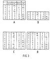
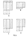
- Figure 3 shows the chain lists for the sections A, B, C and D of the network of Figure 2, while Figure 4 shows the node lists.
- a first field "1-C" in each record (row) identifies the 1-cell (road segment) to which the record relates.
- Figure 3 shows the reference letters a, b, ... h which identify the 1-cells relevant to section A.
- the field 1-C will contain pointers to locations in the data parcel where the remaining information decribing that 1-cell is stored. That information could alternatively be stored in a further field of the chain list record, so that the complete description of 1-cell can be located by a single pointer value.
- the remaining four fields of the chain list record relate to the ends of the 1-cell, and are grouped in two pairs L and R, corresponding to the "beginning" and "end” of the 1-cell respectively.
- L and R the left-most end of a 1-cell
- the right-most end is called the "end”
- L and R the references L and R.
- the upper end may be chosen to be the beginning.
- a first field 0-C identifies the beginning 0-cell for the 1-cell
- a thread pointer TP identifies a further 1-cell which terminates at the same 0-cell.
- Fields 0-C and TP under R do the same for the end node of the 1-cell.
- the thread pointers are chosen systematically following a particular sense of rotation (clockwise, in this embodiment) about their respective 0-cells (nodes).
- the beginning node for 1-cell c is node 1, as indicated under L, 0-C in the chain list record for which the field 1-C is "c".
- Another 1-cell joining 1-cell c at node 1 is the 1-cell a, as indicated by the thread pointer under L, TP.
- This 1-cell a was chosen because it is the first 1-cell at node 1 in a clockwise sense of rotation about the node 1, starting from the 1-cell c to which the record relates.
- All 1-cells terminating at node 1 can be found in this rotational order by following thread pointers TP under L or R until they point back to the starting 1-cell.
- the record for 1-cell c points to 1-cell a
- the TP associated with node 1 in the record for 1-cell a points to 1-cell b
- the TP associated with node 1 in the record for 1-cell b points back to 1-cell c, indicating that all 1-cells have been found which terminate at node 1.
- the record for node 1 (third row from the bottom) need only specify one 1-cell, by means of a thread pointer TP.
- A, 1-cell b is identified by the thread pointer, TP for node 1, and the remaining 1-cells, c and a, can be identified in the clockwise order by following thread pointers through the chain list ( Figure 3), as described above.
- the 1-cell indicated by the thread pointer in the node list record for a non-boundary node is chosen to be the first 1-cell in the clockwise sense of rotation, starting from the North (up) direction.
- Such techniques are particularly useful in association with a read-only storage device such as a CD-ROM.
- the database can nevertheless be updated with special supplementary information until compilation of a new database on CD-ROM is justified.
- Such supplementary information could be supplied for example by local radio data broadcasts, or on magnetic disks or memory cards.
- the compilation of a new database may be justified more frequently.
- the nil-pointer conveys no information other than that the associated node is a boundary node and the next 1-cell clockwise is not in the present section.
- a reduction in the necessary size of the thread pointer fields TP under L and R for all records in the chain list since the 1-cells need only be identified uniquely within the current section. In other words, the information has been added to the chain list that all indicated 1-cells are within the current section.
- the lost information is replaced in the node lists of Figure 4 by providing longer records for (only) the boundary nodes.
- the longer records and the normal (non-boundary) node records are grouped in two separate node lists. Again, it should be remembered that these longer records will be a small minority in a practical database. For example, in the CD-ROM-based car navigation system described, a parcel size giving 12 to 18 percent boundary nodes has been found satisfactory. Each boundary node gives rise to at least two long records, since it appears in at least two neighbouring sections.
- the additional field 0-C' in the record for a boundary node identifies a neighbouring section (A, B, C, D etcetera), and the node in that neighbouring section's node list which is the same boundary node.
- the field 0-C' in the record for node 25 in the node list for section A identifies node 25 in section C.
- the symbol "?” is used for neighbouring sections not shown in Figure 2.
- the field 0-C' for node 25 in the node list for section C refers to node 25 in section A.
- the thread pointer field TP of each record for a boundary node in the node list points to the first 1-cell terminated by that node, counting clockwise from the section boundary.
- the thread pointer field TP of each record for a boundary node in the node list points to the first 1-cell terminated by that node, counting clockwise from the section boundary.
- traversing 1-cell f in section A in the direction from L to R, one encounters the node 22 in field 0-C under R in the chain list record for 1-cell f.
- This thread pointer turns out to be a nil-pointer, so one looks to the node list record for the associated node 22.
- Field 0-C' in this node list record identifies the boundary node beyond the section boundary as being node 22 in section B.
- Figures 5 and 6 illustrate one system for treating a real node which coincides with the boundary between two or more sections.
- a small part of a network is shown, bridging three sections, E, F and G.
- a node 28 occurs, which terminates four 1-cells, aa, bb, cc and dd. Of these four 1-cells, aa and bb are in section F while cc and dd are in section G.
- a second node 29 coincides with the boundary intersection at which all three sections, E, F and G meet.
- Three 1-cells ee, ff and gg lead from this node into sections E, F and G respectively.
- Figure 6 illustrates a compact and systematic ordering of the chain list and node list references describing this network, which provides maximal consistency with the organization as described already, even at these unusual nodes 28 and 29.
- the three sections E, F and G have been separated, as indeed they are separated in respective parcels of the database.
- the reference signs for the 0-cells (nodes) 28 and 29 have been omitted for clarity, since these features are clearly recognizable by comparison with Figure 5.
- FIG. 6 What are shown in Figure 6 are the various pointers in the chain lists and node lists for the sections E, F and G which enable a route to be followed through the network rapidly and systematically, even across the section boundaries.
- a pointer labelled TP from the node to a 1-cell in the neighbouring section is provided by the field TP of the node list record for that node in the neighbouring section.
- the field 0-C' for node 28 in the node list of section F points to the node 28 in section G
- the field TP for the node 28 in the node list of section C points to the 1-cell cc.
- the 1-cell cc is chosen because it is the first 1-cell leading from node 28 into section G, counting clockwise from the section boundary.
- To get from 1-cell bb in the chain list of section F to the 1-cell cc is a two-step process of consulting the node lists for section F and then section G in response to the discovery of the nil-pointer in the chain list record for 1-cell bb in section F.
- the complete set of four 1-cells radiating from node 28 can be found in this manner, in the correct clockwise sequence aa, bb, cc, dd.
- a boundary node might appear in 2, 3 or 4 different sections.
- a node might appear in even more than 4 sections.
- the clockwise ordering system adopted at node 29 in Figure 6 can be extended infinitely enabling a consistent approach to database organization at all real and boundary nodes.
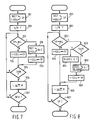
- the flowchart of Figure 7 illustrates a method of tracing a route through a network which is stored in a database in the manner described above. Steps 701 to 709 of this method are described as follows.
- a special case of path following occurs when it is desired to identify the chain of 1-cells that surrounds a particular 2-cell.
- the car When navigating a car, for example, the car many often deviate from the known network when it enters private land, or enters a newly-developed area not yet included in the database. In this situation, knowledge of all 1-cells surrounding the 2-cell is useful for detecting when and where the car returns to the known network.
- the L or R decision in step 802 is based not on any actual direction of traversing the 1-cell, but on which 2-cell it is desired to trace.
- the 2-cell X in the above example requires looking toward node 24 on 1-cell g, and node 24 is the 0-cell under R in the chain list record for 1-cell g ( Figure 3, A).
- Step 807 indicates that when tracing the boundary of a 2-cell, the destination is the starting point SP.
- the steps 803, 808 and 809 enable 2-cells to be traced across section boundaries, in the same way as the steps 703, 708 and 709 in the general case of Figure 7.
- a 2-cell is too large to be considered as a whole, or merely that most of it is not relevant.
- the parts of the 2-cell X which are in sections B, C and D are hardly relevant to the immediate navigation problem. It may be that the data parcels for these sections are not even in the working memory.
- a single 2-cell might in some cases extend through so many sections that loading them all into the working memory is impossible. In such cases, the 2-cell must be "clipped" to a more reasonable area, and the question arises whether the section boundaries can be used to simplify such clipping.
- step 810 it is determined whether the area beyond the section boundary is relevant, or can be skipped. If it can be skipped, step 811 updates the current node to be the next one in the node list for the section. Of course, if the first boundary node is the last one in the node list (for example node 21 in section A), step 811 will look to the first record in the node list (node 11), rather than to the following, non-boundary node (node 1).
- each boundary node record should contain a pointer to the next boundary node in the opposite (anti-clockwise) sense of rotation.
- a pointer occupies space, however, and the use of ordering exploites more fully the principle of concentrating the processing effort into the database compilation, thereby reducing the processing effort in the in-car system using the database.
- topological networks other than road networks, including for example other transport networks, telecommunications networks, and distribution networks for oil, gas, water etcetera.
Landscapes
- Engineering & Computer Science (AREA)
- Databases & Information Systems (AREA)
- Theoretical Computer Science (AREA)
- Remote Sensing (AREA)
- Data Mining & Analysis (AREA)
- Physics & Mathematics (AREA)
- General Engineering & Computer Science (AREA)
- General Physics & Mathematics (AREA)
- Information Retrieval, Db Structures And Fs Structures Therefor (AREA)
Claims (12)
- Verfahren zur Speicherung von digitalen Daten, die ein topologisches Netzwerk darstellen, wobei das Netzwerk eine Gruppe von 0-Zellen (11-27) (Knotenpunkten) und eine Gruppe von 1-Zellen (a-z) umfaßt und in Abschnitte (A-D) unterteilt ist, die diskreten Datenparzellen zur Speicherung in einem Massenspeicher (104) entsprechen, wobei ein Grenzknotenpunkt (22-27) an jedem Punkt definiert ist, an dem das Netzwerk eine Grenze zwischen Abschnitten überquert, wobei die Datenparzelle für einen bestimmten Abschnitt einen Kettenlisten-Datensatz (Figur 3) für jede 1-Zelle in dem Abschnitt enthält und dieser Kettenlisten-Datensatz zumindest im Fall einer 1-Zelle, die an Nicht-Grenzknotenpunkten endet, Informationen für beide 0-Zellen enthält, die sich auf die Nicht-Grenzknotenpunkte beziehen und wobei diese Informationen auf weitere 1-Zellen in dem Netzwerk verweisen, die an den gleichen Nicht-Grenzknotenpunkten enden, dadurch gekennzeichnet, daß für eine 1-Zelle, die an einem Grenzknotenpunkt endet, die in der genannten 1-Zelle für den betreffenden Knotenpunkt enthaltenen Informationen einen Indikator (NIL) enthalten, der angibt, daß es sich bei dem genannten Knotenpunkt um einen Grenzknotenpunkt handelt; und dadurch, daß die Datenparzelle weitere Informationen (O-C') außerhalb des Kettenlisten-Datensatzes der genannten 1-Zelle enthält, wobei diese weiteren Informationen auf eine 1-Zelle außerhalb des Netzwerkabschnitts verweisen, auf den sich die Parzelle bezieht, und die an dem gleichen Grenzknotenpunkt endet.
- Verfahren nach Anspruch 1, wobei die weiteren Informationen in der Datenparzelle für einen bestimmten Abschnitt des Netzwerks einen Knotenpunktlisten-Datensatz (Figur 4) für jeden Knotenpunkt in dem Abschnitt enthalten, und wobei der Knotenpunktlisten-Datensatz für einen Grenzknotenpunkt in einem bestimmten Abschnitt einen Verweis (0-C') auf einen entsprechenden Knotenpunkt in einem benachbarten Abschnitt sowie einen verkettenden Zeiger (TP) enthält, der auf eine 1-Zelle in dem bestimmten Abschnitt verweist, aber auch keinen direkten Verweis auf eine 1-Zelle außerhalb des bestimmten Abschnitts.
- Verfahren nach Anspruch 2, wobei der Kettenlisten-Datensatz für eine 1-Zelle Verweise (0-C) auf einen ersten und einen zweiten Knotenpunkt enthält, die die 1-Zelle beenden, und außerdem entsprechende erste und zweite verkettende Zeiger (TP) enthält, die jeweils eine weitere 1-Zelle angeben, welche durch den ersten bzw. durch den zweiten Knotenpunkt beendet wird, mit der Ausnahme, daß wo ein Knotenpunkt, auf den in einem Kettenlisten-Datensatz verwiesen wird, ein Grenzknotenpunkt ist und keine weitere 1-Zelle in dem gleichen Abschnitt anzugeben bleibt, der Indikator, der angibt, daß es sich bei dem Knotenpunkt um einen Grenzknotenpunkt handelt, einen speziellen Zeiger (NIL) an der dem verkettenden Zeiger zugewiesenen Stelle enthält.
- Verfahren nach Anspruch 3, wobei die weitere 1-Zelle, die durch jeden verkettenden Zeiger in einem Kettenlisten-Datensatz angegeben wird, systematisch gewählt wird, indem einer bestimmten Drehrichtung um den beendenden Knotenpunkt gefolgt wird, während der verkettende Zeiger in dem Knotenpunktlisten-Datensatz für jeden Grenzknotenpunkt die erste 1-Zelle innerhalb des Abschnitts angibt, wobei von der Abschnittgrenze in der bestimmten Drehrichtung um den Grenzknotenpunkt gezählt wird (Figur 6).
- Verfahren nach Anspruch 4, wobei der Knotenpunktlisten-Datensatz bei einem Grenzknotenpunkt, der sich auf der Grenze von drei oder mehr Abschnitten befindet, nur auf den entsprechenden Grenzknotenpunkt in dem Abschnitt verweist, der als nächstes in der bestimmten Drehrichtung folgt.
- Verfahren nach Anspruch 4 oder 5, wobei die Datenparzelle für einen Abschnitt des Netzwerks Informationen (0-C') enthält, die die Grenzknotenpunkte entsprechend der Drehrichtung um die Abschnittgrenze miteinander verknüpfen, die zu der bestimmten Drehrichtung, nach der die 1-Zellen durch die verkettenden Zeiger in den Kettenlisten-Datensätzen angegeben werden, entgegengesetzt ist.
- Verfahren zum Identifizieren einer weiteren 1-Zelle (a-z) bei einer gegebenen aktuellen 1-Zelle (a-z) und einer Richtung zum Durchqueren dieser 1-Zelle in einem topologischen Netzwerkabschnitt (A-D), der durch eine Datenparzelle dargestellt ist, welche in einem Massenspeicher entsprechend einem der Ansprüche 1 bis 6 gespeichert ist, wobei das Verfahren die folgenden Schritte umfaßt:die von dem genannten beendenden Knotenpunkt ausgeht (706); dadurch gekennzeichnet, daß Schritt (b) alternativ die Suche nach einem Indikator (NIL) umfaßt, der angibt, daß der genannte beendende Knotenpunkt ein Grenzknotenpunkt ist, und(a) in dem Kettenlisten-Datensatz für die aktuelle 1-Zelle den beendenden Knotenpunkt (L, R) in der bestimmten Richtung der Durchquerung der 1-Zelle auffinden (703); und(b) in diesem Kettenlisten-Datensatz nach einem Verweis auf eine weitere 1-Zelle suchen,
daß, falls der genannte Indikator gefunden wird, ein Schritt (b1) durchgeführt wird (709), in dem Informationen (O-C'), auf die von dem Kettenlisten-Datensatz und außerhalb des Kettenlisten-Datensatzes verwiesen wird, benutzt werden, um einen Verweis auf die weitere 1-Zelle in der Datenparzelle eines benachbarten Abschnitts (A-D) des Netzwerks zu lokalisieren. - Verfahren nach Anspruch 7, wobei die Netzwerkdaten entsprechend einem der Ansprüche 2 bis 6 gespeichert wurden, wobei der Schritt (b1) das Konsultieren des Knotenpunktlisten-Datensatzes (Figur 4) für diesen beendenden Knotenpunkt umfaßt, um den entsprechenden Knotenpunkt in einem benachbarten Abschnitt des Netzwerks zu identifizieren, und die Benutzung des verkettenden Zeigers (TP) des entsprechenden Knotenpunktlisten-Datensatzes in einer Datenparzelle, die den benachbarten Abschnitt darstellt, um die weitere 1-Zelle zu identifizieren, die von dem entsprechenden Knotenpunkt in den benachbarten Netzwerkabschnitt führt.
- Verfahren zum Identifizieren einer Reihe von 1-Zellen (a-z), die eine Strekke durch ein topologisches Netzwerk bilden, das durch Datenparzellen dargestellt wird, die entsprechend einem der Ansprüche 1 bis 6 in einem Massenspeicher (104) gespeichert wurden, bei einer gegebenen aktuellen 1-Zelle und der Richtung der Durchquerung dieser 1-Zelle, wobei das Verfahren das wiederholte Finden einer weiteren 1-Zelle entsprechend einem Verfahren nach Anspruch 7 oder Anspruch 8 umfaßt, wobei jedesmal die weitere 1-Zelle zu einer neuen aktuellen 1-Zelle gemacht wird und jedesmal die aktuelle 1-Zelle nur durchquert wird, wenn sie einen Teil der gewünschten Route bildet.
- Verfahren zum Identifizieren einer Reihe von 1-Zellen (f, g, w, x), die eine bestimmte 2-Zelle (X) in einem topologischen Netzwerk abgrenzen, das entsprechend einem Verfahren nach einem der Ansprüche 4 bis 7 gespeichert ist, wobei das Verfahren die folgenden Schritte umfaßt:(c) Wählen einer ersten aktuellen 1-Zelle, die die bestimmte 2-Zelle begrenzt, und Wählen einer Richtung, um die 2-Zelle in einer Drehrichtung zu umkreisen, die derjenigen Drehrichtung entgegengesetzt ist, nach der die 1-Zellen durch die verkettenden Zeiger in den Kettenlisten-Datensätzen angegeben werden, und(d) Anwenden eines Verfahrens nach Anspruch 9, um eine Reihe von 1-Zellen zu identifizieren, wobei die erste 1-Zelle, die durch den verkettenden Zeiger bei jeder 0-Zelle angegeben wird, durchquert wird, bis die erste aktuelle 1-Zelle wieder erreicht ist.
- Verfahren nach Anspruch 10, wobei bei Erreichen eines Grenzknotenpunktes ermittelt wird, ob der Teil der bestimmten 2-Zelle, welcher jenseits der Abschnittgrenze liegt, von Interesse ist, und - wenn dieser Teil nicht von Interesse ist - der Schritt (b) ersetzt wird durch Schritt (b2) (810), in dem der nächstfolgende Grenzknotenpunkt auf der Abschnittgrenze entsprechend der genannten entgegengesetzten Drehrichtung um die 2-Zellen-Grenze herum identifiziert wird und in dem der Knotenpunktlisten-Datensatz für den genannten nächsten folgenden Grenzknotenpunkt benutzt wird, um eine weitere 1-Zelle der Reihe innerhalb der Abschnittgrenze zu identifizieren.
- Gerät (102, 103) zum Lesen einer topologischen Datenbank, die entsprechend einem Verfahren nach einem der Ansprüche 1 bis 6 in einer Massenspeichervorrichtung (104) gespeichert ist, wobei das Gerät folgendes umfaßt:Mittel, um aus einer Massenspeichervorrichtung eine erste Datenparzelle zu lesen, die einen ersten Abschnitt eines topologischen Netzwerks darstellt;Mittel, um aus der Datenparzelle einen Kettenlisten-Datensatz zu lesen, der einer 1-Zelle (a-z) in dem ersten Abschnitt (A-D) des Netzwerks entspricht, wobei der Kettenlisten-Datensatz in einem Fall, in dem die 1-Zelle durch einen Nicht-Grenzknotenpunkt beendet wird, einen Verweis auf eine weitere 1-Zelle in dem ersten Abschnitt enthält, die ebenfalls durch diesen Knotenpunkt beendet wird, oder in einem Fall, in dem die 1-Zelle durch einen Grenzknotenpunkt beendet wird, einen Indikator (NIL) für diesen letztgenannten Fall und einen Verweis auf weitere Informationen (0-C') außerhalb des Kettenlisten-Datensatzes enthält;Mittel, die auf das Lesen des Indikators in dem Kettenlisten-Datensatz reagieren, um die genannten weiteren Informationen außerhalb des Kettenlisten-Datensatzes zu konsultieren, um einen benachbarten zweiten Abschnitt (A-D) des Netzwerks zu identifizieren; undMittel, um eine zweite Datenparzelle für den zweiten Abschnitt (A-D) des Netzwerks zu lesen und um Informationen in der zweiten Datenparzelle zu nutzen, um eine weitere 1-Zelle zu identifizieren, die von dem entsprechenden Grenzknotenpunkt in den zweiten Abschnitt des Netzwerks führt.
Priority Applications (1)
| Application Number | Priority Date | Filing Date | Title |
|---|---|---|---|
| EP91202453A EP0479364B1 (de) | 1990-10-01 | 1991-09-23 | Verfahren zur Speicherung eines topologischen Netzwerkes und Verfahren und Geräte, um eine Reihe von 1-Zellen zu identifizieren |
Applications Claiming Priority (3)
| Application Number | Priority Date | Filing Date | Title |
|---|---|---|---|
| EP90202587 | 1990-10-01 | ||
| EP90202587 | 1990-10-01 | ||
| EP91202453A EP0479364B1 (de) | 1990-10-01 | 1991-09-23 | Verfahren zur Speicherung eines topologischen Netzwerkes und Verfahren und Geräte, um eine Reihe von 1-Zellen zu identifizieren |
Publications (2)
| Publication Number | Publication Date |
|---|---|
| EP0479364A1 EP0479364A1 (de) | 1992-04-08 |
| EP0479364B1 true EP0479364B1 (de) | 1999-05-26 |
Family
ID=26126026
Family Applications (1)
| Application Number | Title | Priority Date | Filing Date |
|---|---|---|---|
| EP91202453A Expired - Lifetime EP0479364B1 (de) | 1990-10-01 | 1991-09-23 | Verfahren zur Speicherung eines topologischen Netzwerkes und Verfahren und Geräte, um eine Reihe von 1-Zellen zu identifizieren |
Country Status (1)
| Country | Link |
|---|---|
| EP (1) | EP0479364B1 (de) |
Families Citing this family (4)
| Publication number | Priority date | Publication date | Assignee | Title |
|---|---|---|---|---|
| WO1997000425A2 (en) * | 1995-06-16 | 1997-01-03 | Philips Electronics N.V. | System for joining elements to complex junctions and links in road network representation for vehicles |
| KR100443495B1 (ko) * | 1998-11-24 | 2004-08-09 | 마쯔시다덴기산교 가부시키가이샤 | 디지털 지도파일의 데이터구조 |
| DE102009001078A1 (de) * | 2009-02-23 | 2010-08-26 | Robert Bosch Gmbh | Verfahren zum Bereitstellen eines Wegenetzwerks |
| CN117742667A (zh) * | 2024-02-19 | 2024-03-22 | 北京智行者科技股份有限公司 | 图形连线中路径的确定方法及装置 |
Family Cites Families (3)
| Publication number | Priority date | Publication date | Assignee | Title |
|---|---|---|---|---|
| NL8701738A (nl) * | 1987-07-23 | 1989-02-16 | Philips Nv | Werkwijze voor het opslaan van een topologisch netwerk in een geheugen en voor het opzoeken van een 2-cel uit dat netwerk, alsmede inrichting voor het uitvoeren van de werkwijze voor het opzoeken. |
| NL8702014A (nl) * | 1987-08-28 | 1989-03-16 | Philips Nv | Routebepalingseenheid. |
| NL8802833A (nl) * | 1988-11-17 | 1990-06-18 | Koninkl Philips Electronics Nv | Werkwijze voor kavel-georienteerde route-planning, alsmede navigatiesysteem met een route-planner voor het uitvoeren van een dergelijke werkwijze. |
-
1991
- 1991-09-23 EP EP91202453A patent/EP0479364B1/de not_active Expired - Lifetime
Also Published As
| Publication number | Publication date |
|---|---|
| EP0479364A1 (de) | 1992-04-08 |
Similar Documents
| Publication | Publication Date | Title |
|---|---|---|
| US5754846A (en) | Method of storing a topological network, and methods and apparatus for identifying series of 1-cells in a network stored by such a method | |
| JP4498486B2 (ja) | 地理データベースにおけるデータ型のインタリービング、及びそれをナビゲーション応用に使用する方法 | |
| EP0219930B1 (de) | Aufzeichnen und Wiederauffinden einer Representation von topologischen Strukturen | |
| JP4447585B2 (ja) | 物理的媒体で地理上のデータを使用し、記憶するためのシステムと方法 | |
| US6298302B2 (en) | Navigation system for providing an optimal route from traffic messages | |
| US7266560B2 (en) | Parcelized geographic data medium with internal spatial indices and method and system for use and formation thereof | |
| EP0807803B1 (de) | Strassenkarteninformationswiedergabevorrichtung, Aufzeichnungsmedium und Übertragungsverfahren | |
| US5953722A (en) | Method and system for forming and using geographic data | |
| EP1058197B1 (de) | Methode und System zur Bildung, Speicherung und Benutzung von Datensätzen | |
| US6556919B2 (en) | Map data storage medium | |
| US5706503A (en) | Method of clustering multi-dimensional related data in a computer database by combining the two verticles of a graph connected by an edge having the highest score | |
| CA2652503C (en) | Data updating system, terminal device, server, and method of data updating | |
| JPH06507747A (ja) | 交通無線受信機 | |
| CN102142022B (zh) | 地图数据及其制备方法、数据产品、存储介质和导航设备 | |
| US4792937A (en) | Process for the management of files on a non-erasable information carrier | |
| US5845226A (en) | Navigation system for leading to a destination and recording medium used for the navigation system | |
| JP4510286B2 (ja) | デジタルマップの処理方法 | |
| US6081802A (en) | System and method for accessing compactly stored map element information from memory | |
| EP0479364A1 (de) | Verfahren zur Speicherung eines topologischen Netzwerkes und Verfahren und Geräte, um eine Reihe von 1-Zellen zu identifizieren | |
| WO1995002218A1 (en) | Data management using nested records and code points | |
| JP3144850B2 (ja) | 位相網記憶方法とそのような網の1セルを識別する方法及び装置 | |
| EP0302547B1 (de) | Vorrichtung zur Durchführung eines Suchverfahrens in einer topologischen Representation eines geographischen Verbindungsnetzes. | |
| CN100592290C (zh) | 一种地图无缝连接方法 | |
| JP2004020303A (ja) | 情報更新システム | |
| JP2006084206A (ja) | ナビゲーション装置 |
Legal Events
| Date | Code | Title | Description |
|---|---|---|---|
| PUAI | Public reference made under article 153(3) epc to a published international application that has entered the european phase |
Free format text: ORIGINAL CODE: 0009012 |
|
| AK | Designated contracting states |
Kind code of ref document: A1 Designated state(s): DE FR GB IT SE |
|
| 17P | Request for examination filed |
Effective date: 19920924 |
|
| 17Q | First examination report despatched |
Effective date: 19960112 |
|
| GRAG | Despatch of communication of intention to grant |
Free format text: ORIGINAL CODE: EPIDOS AGRA |
|
| RAP3 | Party data changed (applicant data changed or rights of an application transferred) |
Owner name: KONINKLIJKE PHILIPS ELECTRONICS N.V. |
|
| GRAG | Despatch of communication of intention to grant |
Free format text: ORIGINAL CODE: EPIDOS AGRA |
|
| GRAH | Despatch of communication of intention to grant a patent |
Free format text: ORIGINAL CODE: EPIDOS IGRA |
|
| RAP1 | Party data changed (applicant data changed or rights of an application transferred) |
Owner name: MANNESMANN VDO AKTIENGESELLSCHAFT |
|
| GRAH | Despatch of communication of intention to grant a patent |
Free format text: ORIGINAL CODE: EPIDOS IGRA |
|
| GRAA | (expected) grant |
Free format text: ORIGINAL CODE: 0009210 |
|
| AK | Designated contracting states |
Kind code of ref document: B1 Designated state(s): DE FR GB IT SE |
|
| REF | Corresponds to: |
Ref document number: 69131270 Country of ref document: DE Date of ref document: 19990701 |
|
| ET | Fr: translation filed | ||
| PLBE | No opposition filed within time limit |
Free format text: ORIGINAL CODE: 0009261 |
|
| STAA | Information on the status of an ep patent application or granted ep patent |
Free format text: STATUS: NO OPPOSITION FILED WITHIN TIME LIMIT |
|
| 26N | No opposition filed | ||
| REG | Reference to a national code |
Ref country code: GB Ref legal event code: IF02 |
|
| PGFP | Annual fee paid to national office [announced via postgrant information from national office to epo] |
Ref country code: SE Payment date: 20040907 Year of fee payment: 14 Ref country code: GB Payment date: 20040907 Year of fee payment: 14 |
|
| PGFP | Annual fee paid to national office [announced via postgrant information from national office to epo] |
Ref country code: FR Payment date: 20040921 Year of fee payment: 14 |
|
| PGFP | Annual fee paid to national office [announced via postgrant information from national office to epo] |
Ref country code: DE Payment date: 20041118 Year of fee payment: 14 |
|
| PG25 | Lapsed in a contracting state [announced via postgrant information from national office to epo] |
Ref country code: IT Free format text: LAPSE BECAUSE OF NON-PAYMENT OF DUE FEES;WARNING: LAPSES OF ITALIAN PATENTS WITH EFFECTIVE DATE BEFORE 2007 MAY HAVE OCCURRED AT ANY TIME BEFORE 2007. THE CORRECT EFFECTIVE DATE MAY BE DIFFERENT FROM THE ONE RECORDED. Effective date: 20050923 Ref country code: GB Free format text: LAPSE BECAUSE OF NON-PAYMENT OF DUE FEES Effective date: 20050923 |
|
| PG25 | Lapsed in a contracting state [announced via postgrant information from national office to epo] |
Ref country code: SE Free format text: LAPSE BECAUSE OF NON-PAYMENT OF DUE FEES Effective date: 20050924 |
|
| PG25 | Lapsed in a contracting state [announced via postgrant information from national office to epo] |
Ref country code: DE Free format text: LAPSE BECAUSE OF NON-PAYMENT OF DUE FEES Effective date: 20060401 |
|
| EUG | Se: european patent has lapsed | ||
| GBPC | Gb: european patent ceased through non-payment of renewal fee |
Effective date: 20050923 |
|
| PG25 | Lapsed in a contracting state [announced via postgrant information from national office to epo] |
Ref country code: FR Free format text: LAPSE BECAUSE OF NON-PAYMENT OF DUE FEES Effective date: 20060531 |
|
| REG | Reference to a national code |
Ref country code: FR Ref legal event code: ST Effective date: 20060531 |