EP0479464B1 - Steuerung eines Getriebes unter Berücksichtigung der Viskosität des Getriebeöls - Google Patents
Steuerung eines Getriebes unter Berücksichtigung der Viskosität des Getriebeöls Download PDFInfo
- Publication number
- EP0479464B1 EP0479464B1 EP91308630A EP91308630A EP0479464B1 EP 0479464 B1 EP0479464 B1 EP 0479464B1 EP 91308630 A EP91308630 A EP 91308630A EP 91308630 A EP91308630 A EP 91308630A EP 0479464 B1 EP0479464 B1 EP 0479464B1
- Authority
- EP
- European Patent Office
- Prior art keywords
- transmission
- value
- input shaft
- logic rules
- high viscosity
- Prior art date
- Legal status (The legal status is an assumption and is not a legal conclusion. Google has not performed a legal analysis and makes no representation as to the accuracy of the status listed.)
- Expired - Lifetime
Links
- 230000005540 biological transmission Effects 0.000 title claims description 85
- 239000000314 lubricant Substances 0.000 title claims description 37
- 238000000034 method Methods 0.000 claims description 25
- 230000009347 mechanical transmission Effects 0.000 claims description 15
- 230000008859 change Effects 0.000 claims description 11
- 230000007935 neutral effect Effects 0.000 claims description 8
- 230000001360 synchronised effect Effects 0.000 claims description 7
- 230000004044 response Effects 0.000 claims description 3
- 230000000694 effects Effects 0.000 claims 2
- 230000010365 information processing Effects 0.000 claims 2
- 239000000446 fuel Substances 0.000 description 3
- 239000012530 fluid Substances 0.000 description 2
- 230000004048 modification Effects 0.000 description 2
- 238000012986 modification Methods 0.000 description 2
- 230000008569 process Effects 0.000 description 2
- 239000000523 sample Substances 0.000 description 2
- 230000001133 acceleration Effects 0.000 description 1
- 230000009471 action Effects 0.000 description 1
- 230000000712 assembly Effects 0.000 description 1
- 238000000429 assembly Methods 0.000 description 1
- 238000010276 construction Methods 0.000 description 1
- 239000002826 coolant Substances 0.000 description 1
- 230000008878 coupling Effects 0.000 description 1
- 238000010168 coupling process Methods 0.000 description 1
- 238000005859 coupling reaction Methods 0.000 description 1
- 230000008676 import Effects 0.000 description 1
- 230000000977 initiatory effect Effects 0.000 description 1
- 238000009434 installation Methods 0.000 description 1
- 238000005461 lubrication Methods 0.000 description 1
- 230000007246 mechanism Effects 0.000 description 1
Images
Classifications
-
- B—PERFORMING OPERATIONS; TRANSPORTING
- B60—VEHICLES IN GENERAL
- B60W—CONJOINT CONTROL OF VEHICLE SUB-UNITS OF DIFFERENT TYPE OR DIFFERENT FUNCTION; CONTROL SYSTEMS SPECIALLY ADAPTED FOR HYBRID VEHICLES; ROAD VEHICLE DRIVE CONTROL SYSTEMS FOR PURPOSES NOT RELATED TO THE CONTROL OF A PARTICULAR SUB-UNIT
- B60W10/00—Conjoint control of vehicle sub-units of different type or different function
- B60W10/04—Conjoint control of vehicle sub-units of different type or different function including control of propulsion units
- B60W10/06—Conjoint control of vehicle sub-units of different type or different function including control of propulsion units including control of combustion engines
-
- B—PERFORMING OPERATIONS; TRANSPORTING
- B60—VEHICLES IN GENERAL
- B60W—CONJOINT CONTROL OF VEHICLE SUB-UNITS OF DIFFERENT TYPE OR DIFFERENT FUNCTION; CONTROL SYSTEMS SPECIALLY ADAPTED FOR HYBRID VEHICLES; ROAD VEHICLE DRIVE CONTROL SYSTEMS FOR PURPOSES NOT RELATED TO THE CONTROL OF A PARTICULAR SUB-UNIT
- B60W10/00—Conjoint control of vehicle sub-units of different type or different function
- B60W10/10—Conjoint control of vehicle sub-units of different type or different function including control of change-speed gearings
- B60W10/11—Stepped gearings
-
- B—PERFORMING OPERATIONS; TRANSPORTING
- B60—VEHICLES IN GENERAL
- B60W—CONJOINT CONTROL OF VEHICLE SUB-UNITS OF DIFFERENT TYPE OR DIFFERENT FUNCTION; CONTROL SYSTEMS SPECIALLY ADAPTED FOR HYBRID VEHICLES; ROAD VEHICLE DRIVE CONTROL SYSTEMS FOR PURPOSES NOT RELATED TO THE CONTROL OF A PARTICULAR SUB-UNIT
- B60W30/00—Purposes of road vehicle drive control systems not related to the control of a particular sub-unit, e.g. of systems using conjoint control of vehicle sub-units
- B60W30/18—Propelling the vehicle
-
- F—MECHANICAL ENGINEERING; LIGHTING; HEATING; WEAPONS; BLASTING
- F16—ENGINEERING ELEMENTS AND UNITS; GENERAL MEASURES FOR PRODUCING AND MAINTAINING EFFECTIVE FUNCTIONING OF MACHINES OR INSTALLATIONS; THERMAL INSULATION IN GENERAL
- F16H—GEARING
- F16H59/00—Control inputs to control units of change-speed- or reversing-gearings for conveying rotary motion
- F16H59/68—Inputs being a function of gearing status
- F16H59/72—Inputs being a function of gearing status dependent on oil characteristics, e.g. temperature, viscosity
-
- B—PERFORMING OPERATIONS; TRANSPORTING
- B60—VEHICLES IN GENERAL
- B60W—CONJOINT CONTROL OF VEHICLE SUB-UNITS OF DIFFERENT TYPE OR DIFFERENT FUNCTION; CONTROL SYSTEMS SPECIALLY ADAPTED FOR HYBRID VEHICLES; ROAD VEHICLE DRIVE CONTROL SYSTEMS FOR PURPOSES NOT RELATED TO THE CONTROL OF A PARTICULAR SUB-UNIT
- B60W2510/00—Input parameters relating to a particular sub-units
- B60W2510/10—Change speed gearings
- B60W2510/1015—Input shaft speed, e.g. turbine speed
- B60W2510/102—Input speed change rate
-
- F—MECHANICAL ENGINEERING; LIGHTING; HEATING; WEAPONS; BLASTING
- F16—ENGINEERING ELEMENTS AND UNITS; GENERAL MEASURES FOR PRODUCING AND MAINTAINING EFFECTIVE FUNCTIONING OF MACHINES OR INSTALLATIONS; THERMAL INSULATION IN GENERAL
- F16H—GEARING
- F16H59/00—Control inputs to control units of change-speed- or reversing-gearings for conveying rotary motion
- F16H59/36—Inputs being a function of speed
- F16H59/38—Inputs being a function of speed of gearing elements
- F16H59/42—Input shaft speed
-
- F—MECHANICAL ENGINEERING; LIGHTING; HEATING; WEAPONS; BLASTING
- F16—ENGINEERING ELEMENTS AND UNITS; GENERAL MEASURES FOR PRODUCING AND MAINTAINING EFFECTIVE FUNCTIONING OF MACHINES OR INSTALLATIONS; THERMAL INSULATION IN GENERAL
- F16H—GEARING
- F16H61/00—Control functions within control units of change-speed- or reversing-gearings for conveying rotary motion ; Control of exclusively fluid gearing, friction gearing, gearings with endless flexible members or other particular types of gearing
- F16H61/02—Control functions within control units of change-speed- or reversing-gearings for conveying rotary motion ; Control of exclusively fluid gearing, friction gearing, gearings with endless flexible members or other particular types of gearing characterised by the signals used
- F16H61/0202—Control functions within control units of change-speed- or reversing-gearings for conveying rotary motion ; Control of exclusively fluid gearing, friction gearing, gearings with endless flexible members or other particular types of gearing characterised by the signals used the signals being electric
- F16H61/0204—Control functions within control units of change-speed- or reversing-gearings for conveying rotary motion ; Control of exclusively fluid gearing, friction gearing, gearings with endless flexible members or other particular types of gearing characterised by the signals used the signals being electric for gearshift control, e.g. control functions for performing shifting or generation of shift signal
- F16H61/0206—Layout of electro-hydraulic control circuits, e.g. arrangement of valves
Definitions
- the present invention relates to a method and apparatus for controlling a transmission by reference to the viscosity of transmission lubricant.
- the present invention relates to a method/apparatus, preferably at system start-up, without requiring a temperature probe, to determine the temperature and/or viscosity of lubricant in a transmission lubricant sump of a fully or partially automated transmission system.
- JP-A-1150028 a method is described for determining a half-clutch position.
- the half-clutch control is intended to improve the feeling of start, speed change etc whilst also preventing excessive clutch wear.
- a new processor uses various input to determine a correlation between shaft declaration rates and temperatures.
- the drawbacks of the prior art have been minimized or overcome by providing a method/apparatus for sensing transmission lubricant sump temperature/viscosity, or at least temperature/viscosity above or below a predetermined reference value, in an automated mechanical transmission system having at least one shaft speed sensor.
- an automatic mechanical transmission system will have a CPU for receiving input signals from an input shaft and an output shaft speed sensor and will have engine, master clutch and transmission shifting mechanism actuators controlled by command output signals issued by the CPU.
- the transmission is shifted to or confirmed as in neutral, the input shaft is caused to rotate at at least a given rotational speed, the master clutch is disengaged and deceleration of the shaft is sensed/calculated.
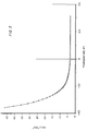
- the deceleration rate of the shaft is an accurate indication of sump temperature, or at least of "cold" or "not cold” conditions.
- a method/apparatus for accurately determining transmission lubricant temperature/viscosity in an automated mechanical transmission system which requires no additional dedicated sensors, CPU input ports or CPU input signal processing capacity.
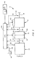
- Figure 1 is a schematic illustration of an automated mechanical transmission system of the type particularly well suited to be controlled by the method/apparatus of the present invention.
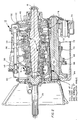
- Figure 2 is a partial elevational view, in cross-section, illustrating a typical synchronized change gear transmission utilizing a lubricant sump in a splash type lubrication system.
- Figure 3 is a graphical representation of the relationship between monitored input shaft deceleration and lubricant sump temperature empirically determined for a particular transmission utilizing a particular specification of transmission lubricant.
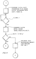
- Figure 4 is a graphical representation, in flow chart format, of the control methods/apparatus of the present invention.
- FIG. 1 schematically illustrates a vehicular automated mechanical transmission system 10 including an automated multi-speed change gear transmission 12 driven by a fuel controlled engine 14, such as a well-known diesel engine, through a coupling such as master friction clutch 16.
- the output of automated transmission 12 is output shaft 18 which is adapted for driving connection to an appropriate vehicle component such as the differential of a drive axle, a transfer case, or the like, as is well known in the prior art.
- crank shaft 20 of engine 14 will drive the driving plates 22 of master friction clutch 16 which are frictionally engageable to driven plates 24 for driving the input shaft 26 of transmission 12.
- the above-mentioned power train components are acted upon and/or monitored by several devices, each of which will be discussed briefly below. These devices will include a throttle pedal position or throttle opening monitor assembly 28 which senses the operator set position of the operator controlled throttle device 30, a fuel control device 32 for controlling the amount of fuel to be supplied to engine 14, and engine speed sensor 34 which senses the rotational speed of the engine, a clutch operator 36 which engages and disengages master clutch 16 and which may also provide information as to the status of the clutch, an input shaft speed sensor 38 for sensing the rotational speed of transmission input shaft 26, a transmission operator 40 which is effective to shift the transmission 12 into a selected gear ratio and to provide a signal indicative of the gear neutral condition and/or the currently engaged gear ratio, and an output shaft speed sensor 42 for sensing the rotational speed of the output shaft 18.
- a throttle pedal position or throttle opening monitor assembly 28 which senses the operator set position of the operator controlled throttle device 30, a fuel control device 32 for controlling the amount of fuel to be supplied to engine 14, and engine speed sensor 34 which senses the
- the above-mentioned devices supply information to and/or accept commands from the central processing unit or control 44.
- the central processing unit 44 may include analog and/or digital electronic calculation and logic circuitry as is known in the prior art.
- the central processing unit 44 will also receive information from a shift control assembly 46 by which the vehicle operator may select a reverse (R) neutral (N) or forward drive (D) mode of operation of the vehicle.
- An electrical power source (not shown) and/or a source of pressurized fluid (not shown) provides electrical and/or pneumatic power to the various sensing, operating and/or processing units.
- the central processing unit 44 may be provided with circuitry for differentiating the input signal from at least sensor 38 to provide a calculated signal indicative of the acceleration and/or deceleration of the transmission input shaft 26.
- the CPU 44 may also be provided with circuitry and/or logic rules to compare the input signals of sensors 38 and 42 to verify and identify that the transmission 12 is engaged in a particular gear ratio, etc.
- Figure 2 is a cross-sectional view of a typical synchronized change gear transmission 12 of the type automated in automated mechanical transmission system 10.
- the transmission 12 includes a transmission housing 48 which will typically support the transmission input shaft 26, the transmission output shaft 18 and a transmission countershaft 50.
- a selected one of the drive gears 52, 54, 56, 58, or 59 or input gear 60 may be coupled to the output shaft 18 by means of the synchronized jaw clutch assemblies 61 to provide the selected forward drive ratio while reverse gear 62 may be selectably coupled to the output shaft 18 to provide reverse operation.
- the input gear 60 which is coupled to the input shaft 26, is constantly engaged with a countershaft drive gear 64 for rotating countershaft 50 and the countershaft gears 66, 68, 70, 72, 73 and idler gear 74, all of which gears are in constant mesh with the drive gears. Accordingly, rotation of input shaft 26 will resolve in rotation of all of the countershaft and drive gears therewith.
- Line 78 indicates the level to which the transmission sump is normally filled with transmission lubricant (at the normal 3 o installation angle in a vehicle). Accordingly, the countershaft gears, and some of the low speed drive gears, are constantly turning within the lubricant sump.
- a control method/control apparatus allowing determination of the transmission lubricant sump temperature/viscosity or at least a determination if lubricant sump temperature/viscosity is greater or less than predetermined reference value, has been devised which requires no additional sensors, nor additional CPU input ports nor additional CPU input signal processing capacity.
- the above method or procedure is preferably performed as a part of the system start up or initiation procedure.
- the master clutch 16 is disengaged, the transmission 12 is shifted to and verified as being in neutral, the master clutch 16 is re-engaged, and the engine 14 is fueled until the input shaft is sensed as rotating at at least a predetermined minimum rotational speed. The master clutch is then disengaged and the engine is defueled.
- the CPU will then sense or calculate the deceleration rate (dIS/dt) of the input shaft 26.
- the measured or calculated deceleration of the input shaft is then compared to a reference value, and, if the deceleration rate exceeds a reference deceleration rate, i.e. if dIS/dt is less than the reference this is taken as an indication that the lubricant sump temperature is below a predetermined value and it is required that cold weather logic routines be utilized. Accordingly, the CPU will adapt cold weather logic.
- the cold weather logic shift routines/shift sequences will be utilized until either the above procedure is again implemented and indicates that the lubricant sump temperature is greater than the predetermined minimum reference value or until the passage of a predetermined period of time.
- the period of time T is selected to assure that continued vehicle operation including churning of the gearing through the lubricant sump has had sufficient time to raise the temperature of the sump above the predetermined minimum value.
- the period of time selected may also be variable with the sensed value of deceleration of the input shaft.
- a new and improved transmission control procedure/apparatus which allows determination of the temperature/viscosity of the transmission lubricant sump, or at least determination of "cold"/"not cold” conditions of the transmission lubricant sump without requiring additional dedicated sensors, nor dedicated sensor input terminals nor input signal processing capacity.
Landscapes
- Engineering & Computer Science (AREA)
- Chemical & Material Sciences (AREA)
- Combustion & Propulsion (AREA)
- Mechanical Engineering (AREA)
- Transportation (AREA)
- General Engineering & Computer Science (AREA)
- Oil, Petroleum & Natural Gas (AREA)
- Automation & Control Theory (AREA)
- Control Of Transmission Device (AREA)
- General Details Of Gearings (AREA)
Claims (14)
- Steuerverfahren zum Erfassen und Reagieren darauf, daß die Getriebesumpf-Schmiermittelviskosität bei einem automatischen mechanischen Getriebesystem (10) eines Fahrzeuges oberhalb eines vorbestimmten Wertes liegt, mit einem fahrhebelgesteuerten Motor (14), einem mechanischen Gangwechselgetriebe (12) mit einer Vielzahl von zwischen einer Getriebeeingangswelle (26) und einer Ausgangswelle (18) wahlweise einrückbaren Untersetzungskombinationen, wobei das Getriebe einen Schmiersumpf (70) aufweist, in dem eine Vielzahl von mit der Eingangswelle ständig treibend verbundenen Zahnrädern (64, 66, 68, 70, 72, 73) wenigstens teilweise eingetaucht sind, und mit einer wahlweise einrückbaren und ausrückbaren Reibungshauptkupplung (16), die antriebsmäßig zwischen dem Motor und dem Getriebe angeordnet ist, wobei das automatische mechanische Getriebesystem zusätzlich eine informationsverarbeitende Einheit (44) mit Mitteln zum Empfang einer Vielzahl von Eingangssignalen einschließlich eines die Drehzahl der Getriebeeingangswelle (38) kennzeichnenden Signales und Mittel zur Verarbeitung der Eingangssignale gemäß vorbestimmter logischer Regeln zur Erzeugung von Befehlsausgangssignalen, wobei das Getriebesystem gemäß der logischen Regeln betrieben wird, sowie Mittel (32, 36, 40) aufweist, die dem Getriebesystem zugeordnet sind und dazu dienen, das Getriebesystem zu betätigen, um das Ein- und Ausrücken ausgewählter Untersetzungskombinationen in Abhängigkeit von den Ausgangssignalen der Verarbeitungseinheit zu bewirken, wobei das Verfahren dadurch gekennzeichnet ist;daß für die Verarbeitungseinheit alternative logische Regeln für hohe Viskosität und nichthohe Viskosität bereitgestellt werden;daß das Getriebe veranlaßt wird, in den Leerlauf geschaltet zu werden, wobei die Drehzahl der Eingangswelle (IS) dann veranlaßt wird, gleich oder größer als ein vorbestimmter Vergleichswert (REF 1) zu sein;dann werden, während das Getriebe im Leerlauf verbleibt, die Kupplung ausgerückt und der Wert der Zeitableitung (dIS/dt) der Drehzahl der Eingangswelle bestimmt unddieser Wert der Zeitableitung der Drehzahl der Eingangswelle mit einem zweiten Vergleichswert (REF 2) verglichen, unddaß, wenn der Wert der Zeitableitung den Vergleichswert überschreitet, logische Regeln für niedrige Viskosität verwendet und, wenn der Wert der Zeitableitung kleiner ist als der zweite Vergleichswert, logische Regeln für hohe Viskosität zur Steuerung des Getriebes verwendet werden.
- Steuerverfahren nach Anspruch 1, mit dem zusätzlichen Schritt, daß nach der Einführung der logischen Regeln für hohe Viskosität für eine vorbestimmte Zeitspanne (T) automatisch zu den logischen Regeln für niedrige Viskosität zurückgekehrt wird.
- Steuerverfahren nach Anspruch 2, bei dem die Zeit (T) als Funktion des Wertes der ersten Zeitableitung variabel ist.
- Steuerverfahren nach den Ansprüchen 1, 2 oder 3, bei dem das Gangwechselgetriebe ein synchronisiertes Gangwechselgetriebe ist.
- Steuerverfahren nach den Ansprüchen 1, 2 oder 3, bei dem die logische Routine lediglich während des Betriebsbeginns des automatischen mechanischen Getriebesystemes durchgeführt wird.
- Steuerverfahren nach den Ansprüchen 1, 2 oder 3, bei dem die Zeitableitung die erste Ableitung nach der Zeit ist.
- Steuerverfahren nach den Ansprüchen 1, 2 oder 3, bei dem der zweite Vergleichswert ein für eine bekannte Kombination des Getriebeaufbaus und der Qualität des Getriebeschmiermittels empirisch bestimmter Wert ist.
- Steuersystem zum Erfassen und Reagieren darauf, daß die Getriebesumpf-Schmiermittelviskosität bei einem automatischen mechanischen Getriebesystem (10) eines Fahrzeuges oberhalb eines vorbestimmten Wertes liegt, mit einem fahrhebelgesteuerten Motor (14), einem mechanischen Gangwechselgetriebe (12) mit einer Vielzahl von zwischen einer Getriebeeingangswelle (26) und einer Ausgangswelle (18) wahlweise einrückbaren Untersetzungskombinationen, wobei das Getriebe einen Schmiersumpf (70) aufweist, in dem eine Vielzahl von mit der Eingangswelle ständig treibend verbundenen Zahnrädern (64, 66, 68, 70, 72, 73) wenigstens teilweise eingetaucht sind, und mit einer wahlweise einrückbaren und ausrückbaren Reibungshauptkupplung (16), die antriebsmäßig zwischen dem Motor und dem Getriebe angeordnet ist, wobei das automatische mechanische Getriebesystem zusätzlich eine informationsverarbeitende Einheit (44) mit Mitteln zum Empfang einer Vielzahl von Eingangssignalen einschließlich eines die Drehzahl der Getriebeeingangswelle (38) kennzeichnenden Signales und Mittel zur Verarbeitung der Eingangssignale gemäß vorbestimmter logischer Regeln zur Erzeugung von Befehlsausgangssignalen, wobei das Getriebesystem gemäß der logischen Regeln betrieben wird, sowie Mittel (32, 36, 40) aufweist, die dem Getriebesystem zugeordnet sind und dazu dienen, das Getriebesystem zu betätigen, um das Ein- und Ausrücken ausgewählter Untersetzungskombinationen in Abhängigkeit von den Ausgangssignalen der Verarbeitungseinheit zu bewirken, wobei das System gekennzeichnet ist, durchMittel, die für die Verarbeitungseinheit alternative logische Regeln für hohe Viskosität und nichthohe Viskosität definieren;Mittel, die das Getriebe veranlassen, in den Leerlauf geschaltet zu werden, und die Drehzahl der Eingangswelle (IS) dann veranlassen, gleich oder größer als ein vorbestimmter Vergleichswert (REF 1) zu sein;Mittel, die dann, während das Getriebe im Leerlauf verbleibt, die Kupplung ausrücken und den Wert der Zeitableitung (dIS/dt) der Drehzahl der Eingangswelle bestimmen undMittel zum Vergleichen dieses Wertes der Zeitableitung der Drehzahl der Eingangswelle mit einem zweiten Vergleichswert (REF 2) undMittel, die bewirken, daß, wenn der Wert der Zeitableitung den Vergleichswert überschreitet, logische Regeln für niedrige Viskosität verwendet werden und, wenn der Wert der Zeitableitung kleiner ist als der zweite Vergleichswert, logische Regeln für hohe Viskosität zur Steuerung des Getriebes verwendet werden.
- Steuersystem nach Anspruch 8, das zusätzlich ein Mittel aufweist, das nach der Einführung der logischen Regeln für hohe Viskosität für eine vorbestimmte Zeitspanne (T) automatisch die Rückkehr zu den logischen Regeln für niedrige Viskosität bewirkt.
- Steuersystem nach Anspruch 9, bei dem die Zeit (T) als Funktion des Wertes der ersten Zeitableitung variabel ist.
- Steuersystem nach den Ansprüchen 8, 9 oder 10, bei dem das Gangwechselgetriebe ein synchronisiertes Gangwechselgetriebe ist.
- Steuersystem nach den Ansprüchen 8, 9 oder 10, bei dem die logische Routine lediglich während des Betriebsbeginns des automatischen mechanischen Getriebesystemes durchgeführt wird.
- Steuersystem nach den Ansprüchen 8, 9 oder 10, bei dem die Zeitableitung die erste Ableitung nach der Zeit ist.
- Steuersystem nach den Ansprüchen 8, 9 oder 10, bei dem der zweite Vergleichswert ein für eine bekannte Kombination des Getriebeaufbaus und der Qualität des Getriebeschmiermittels empirisch bestimmter Wert ist.
Applications Claiming Priority (2)
| Application Number | Priority Date | Filing Date | Title |
|---|---|---|---|
| US07/591,305 US5050451A (en) | 1990-10-01 | 1990-10-01 | Transmission lubricant temperature/viscosity determination method/apparatus |
| US591305 | 1990-10-01 |
Publications (3)
| Publication Number | Publication Date |
|---|---|
| EP0479464A2 EP0479464A2 (de) | 1992-04-08 |
| EP0479464A3 EP0479464A3 (en) | 1993-09-01 |
| EP0479464B1 true EP0479464B1 (de) | 1997-01-02 |
Family
ID=24365957
Family Applications (1)
| Application Number | Title | Priority Date | Filing Date |
|---|---|---|---|
| EP91308630A Expired - Lifetime EP0479464B1 (de) | 1990-10-01 | 1991-09-23 | Steuerung eines Getriebes unter Berücksichtigung der Viskosität des Getriebeöls |
Country Status (6)
| Country | Link |
|---|---|
| US (1) | US5050451A (de) |
| EP (1) | EP0479464B1 (de) |
| JP (1) | JP3194094B2 (de) |
| CA (1) | CA2052503C (de) |
| DE (1) | DE69123920T2 (de) |
| ES (1) | ES2095919T3 (de) |
Cited By (2)
| Publication number | Priority date | Publication date | Assignee | Title |
|---|---|---|---|---|
| DE19915471A1 (de) * | 1999-04-06 | 2000-10-12 | Zahnradfabrik Friedrichshafen | Vorrichtung zur Messung der Getriebeöltemperatur |
| DE10354930B3 (de) * | 2003-11-25 | 2005-08-04 | Adam Opel Ag | Anfahren eines Kraftfaharzeugs bei ungünstigem Klima |
Families Citing this family (18)
| Publication number | Priority date | Publication date | Assignee | Title |
|---|---|---|---|---|
| US5329826A (en) * | 1992-01-22 | 1994-07-19 | Eaton Corporation | Enhanced automated splitter shifting with dual solenoid valves and auto fuel control |
| DE19504650C1 (de) * | 1995-02-13 | 1996-04-04 | Daimler Benz Ag | Einrichtung zur Getriebetemperaturerfassung |
| DE19717252A1 (de) * | 1997-04-24 | 1998-10-29 | Zahnradfabrik Friedrichshafen | Programmierbare Getriebeelektronik für Schaltsystemgetriebe mit Bereichsgruppenschaltung |
| US6052637A (en) * | 1997-06-09 | 2000-04-18 | Eaton Corporation | Clutch adjustment determination |
| DE19743743A1 (de) | 1997-10-02 | 1999-04-15 | Zahnradfabrik Friedrichshafen | Verfahren zum Steuern eines Automatgetriebes |
| US6070119A (en) * | 1999-01-22 | 2000-05-30 | Ford Global Technologies, Inc. | Clutch pressure control for improved transmission engagements and shifts |
| JP2000337494A (ja) * | 1999-05-24 | 2000-12-05 | Aisin Ai Co Ltd | 自動変速機のシフト制御装置及びシフト方法 |
| GB9919179D0 (en) * | 1999-08-16 | 1999-10-20 | Luk Getriebe Systeme Gmbh | Transmission systems |
| SE517743C2 (sv) * | 1999-09-03 | 2002-07-09 | Volvo Lastvagnar Ab | Drivaggregat för ett motorfordon samt sätt att identifiera dragläget hos en i drivaggregatet ingående automatiserad koppling |
| US6374951B1 (en) | 2000-02-22 | 2002-04-23 | Eaton Corporation | Gear isolation shroud for transmission |
| JP5100938B2 (ja) * | 2001-08-28 | 2012-12-19 | アイシン精機株式会社 | 自動変速装置 |
| DE10148203A1 (de) * | 2001-09-28 | 2003-04-10 | Zahnradfabrik Friedrichshafen | Verfahren zur Kupplungsbetätigung bei niedrigen Temperaturen |
| JP4341232B2 (ja) | 2002-11-15 | 2009-10-07 | ダイキン工業株式会社 | 自律型インバータ駆動油圧ユニットの昇温制御方法およびその装置 |
| EP1632689A3 (de) | 2004-09-03 | 2006-04-12 | LuK Lamellen und Kupplungsbau Beteiligungs KG | Verfahren zur Kupplungssteuerung, insbesondere für Parallelschaltgetriebe mit Nasskupplungen oder Nassdoppelkupplungen |
| DE102008053387A1 (de) * | 2007-11-15 | 2009-05-20 | Luk Lamellen Und Kupplungsbau Beteiligungs Kg | Verfahren zur Steuerung einer automatisierten Reibungskupplung |
| CN105209796B (zh) * | 2013-04-12 | 2017-12-12 | 德纳有限公司 | 用于确定润滑剂的剩余使用寿命的监测和预测系统及方法 |
| FR3010738B1 (fr) * | 2013-09-13 | 2015-09-11 | Turbomeca | Procede de surveillance d'un degre de cokefaction au niveau de joints par un arbre de generateur de gaz |
| FR3010737B1 (fr) * | 2013-09-13 | 2015-08-21 | Turbomeca | Surveillance d'un degre de cokefaction au niveau de joints dynamiques par le demarreur |
Family Cites Families (13)
| Publication number | Priority date | Publication date | Assignee | Title |
|---|---|---|---|---|
| US3221851A (en) * | 1963-10-16 | 1965-12-07 | Eaton Mfg Co | Synchronized positive clutches |
| US4361060A (en) * | 1978-01-24 | 1982-11-30 | Smyth Robert Ralston | Mechanical automatic transmission |
| JPS5834257A (ja) * | 1981-08-26 | 1983-02-28 | Toyota Motor Corp | 車両用自動変速機の変速方法および変速制御装置 |
| EP0093313B1 (de) * | 1982-04-19 | 1988-02-03 | Nissan Motor Co., Ltd. | Verfahren zum Verstellen des Übersetzungsverhältnisses eines stufenlosen Getriebes unter Berücksichtigung der Kühlwassertemperatur |
| US4497396A (en) * | 1982-09-20 | 1985-02-05 | Eaton Corporation | Variable mechanical advantage shift lever |
| US4527447A (en) * | 1982-12-06 | 1985-07-09 | Eaton Corporation | Automatic mechanical transmission system |
| GB8418749D0 (en) * | 1984-07-23 | 1984-08-30 | Eaton Ltd | Semi-automatic transmission control |
| US4576065A (en) * | 1984-09-12 | 1986-03-18 | Eaton Corporation | Automatic transmission controls with multiple downshift off-highway mode |
| US4595986A (en) * | 1984-10-09 | 1986-06-17 | Eaton Corporation | Method for control of automatic mechanical transmission system utilizing a microprocessor based electronic controller |
| US4754665A (en) * | 1986-02-05 | 1988-07-05 | Eaton Corporation | Auxiliary transmission section |
| US4779489A (en) * | 1986-06-27 | 1988-10-25 | Borg-Warner Automotive, Inc. | Control system for controlling transmission fluid pressure |
| HU196927B (en) * | 1986-07-01 | 1989-02-28 | Csepeli Autogyar | Method for stage coupling the automatic gear box of motor vehicle depending on the temperature of cooling water |
| US4928235A (en) * | 1988-04-29 | 1990-05-22 | Chrysler Corporation | Method of determining the fluid temperature of an electronic automatic transmission system |
-
1990
- 1990-10-01 US US07/591,305 patent/US5050451A/en not_active Expired - Lifetime
-
1991
- 1991-09-23 EP EP91308630A patent/EP0479464B1/de not_active Expired - Lifetime
- 1991-09-23 ES ES91308630T patent/ES2095919T3/es not_active Expired - Lifetime
- 1991-09-23 DE DE69123920T patent/DE69123920T2/de not_active Expired - Fee Related
- 1991-09-30 CA CA002052503A patent/CA2052503C/en not_active Expired - Fee Related
- 1991-10-01 JP JP28073491A patent/JP3194094B2/ja not_active Expired - Fee Related
Cited By (3)
| Publication number | Priority date | Publication date | Assignee | Title |
|---|---|---|---|---|
| DE19915471A1 (de) * | 1999-04-06 | 2000-10-12 | Zahnradfabrik Friedrichshafen | Vorrichtung zur Messung der Getriebeöltemperatur |
| US6663279B1 (en) | 1999-04-06 | 2003-12-16 | Zf Friedrichshafen Ag | Device for measuring the gearbox oil temperature |
| DE10354930B3 (de) * | 2003-11-25 | 2005-08-04 | Adam Opel Ag | Anfahren eines Kraftfaharzeugs bei ungünstigem Klima |
Also Published As
| Publication number | Publication date |
|---|---|
| DE69123920D1 (de) | 1997-02-13 |
| EP0479464A2 (de) | 1992-04-08 |
| US5050451A (en) | 1991-09-24 |
| JP3194094B2 (ja) | 2001-07-30 |
| CA2052503C (en) | 1995-02-21 |
| DE69123920T2 (de) | 1997-06-05 |
| CA2052503A1 (en) | 1992-04-02 |
| EP0479464A3 (en) | 1993-09-01 |
| ES2095919T3 (es) | 1997-03-01 |
| JPH04300458A (ja) | 1992-10-23 |
Similar Documents
| Publication | Publication Date | Title |
|---|---|---|
| US5050451A (en) | Transmission lubricant temperature/viscosity determination method/apparatus | |
| US6086514A (en) | Clutch control method for determining clutch kiss-point during running conditions | |
| US4852006A (en) | Amt off-highway downshift logic | |
| EP0677684B1 (de) | Adaptive Verfahren und Vorrichtung für Gangschaltung | |
| EP0676566B1 (de) | Verfahren und System zur Bestimmung einer Motorverzögerung | |
| US6482123B2 (en) | Method of controlling heat buildup in a clutch | |
| JP3069798B2 (ja) | 車輌用自動機械式変速システムの制御方法 | |
| EP0683336A1 (de) | Vorrichtung/Verfahren zur Erstellung des Antriebsdrehmoments der Motorzusatzvorrichtungen und Verzögerungsgeschwindigkeit dieses Moments | |
| EP0683335A1 (de) | Einrichtung und Verfahren zur Erfassung des Motorschwungraddrehmoments | |
| GB2213220A (en) | "Failure detection for an automatic transmission" | |
| GB2097075A (en) | Transmission control system in a vehicle | |
| US8849529B2 (en) | Method and system for determining the contact point for a clutch in a vehicle | |
| EP0884212B1 (de) | Bestimmung der Kupplungseinstellung | |
| US5517411A (en) | Neutral attainment control system/method for controlling shifting in vehicular automated mechanical transmission systems | |
| EP0922604B1 (de) | Steuerung eines Getriebes mit elektrischer Schaltbetätigung, insbesondere mit Bestimmung der Kupplungsstellung | |
| EP0244131B1 (de) | Verfahren zum Steuern eines automatischen mechanischen Getriebes einschliesslich Regelung von Kupplungseingriff und Kraftstoff nach einem Schaltvorgang des Getriebes | |
| EP0246035B1 (de) | Verfahren zur Steuerung eines automatischen, mechanischen Getriebesystems mit Brennstoffsteuerung nach der Übersetzungsgetriebe-Änderung | |
| US5345841A (en) | Elevated low idle for coasting in neutral | |
| US20060234831A1 (en) | Method of detecting false neutral in an automated transmission system | |
| US5609552A (en) | Lockup clutch control responsive to degraded ATF fluid condition | |
| EP1268230A1 (de) | Verfahren und vorrichtung zur anzeigung eines schlupfzustands | |
| US4774832A (en) | Engine idling speed sensing system |
Legal Events
| Date | Code | Title | Description |
|---|---|---|---|
| PUAI | Public reference made under article 153(3) epc to a published international application that has entered the european phase |
Free format text: ORIGINAL CODE: 0009012 |
|
| AK | Designated contracting states |
Kind code of ref document: A2 Designated state(s): DE ES FR GB IT NL SE |
|
| PUAL | Search report despatched |
Free format text: ORIGINAL CODE: 0009013 |
|
| AK | Designated contracting states |
Kind code of ref document: A3 Designated state(s): DE ES FR GB IT NL SE |
|
| 17P | Request for examination filed |
Effective date: 19930909 |
|
| 17Q | First examination report despatched |
Effective date: 19941207 |
|
| GRAG | Despatch of communication of intention to grant |
Free format text: ORIGINAL CODE: EPIDOS AGRA |
|
| GRAH | Despatch of communication of intention to grant a patent |
Free format text: ORIGINAL CODE: EPIDOS IGRA |
|
| GRAH | Despatch of communication of intention to grant a patent |
Free format text: ORIGINAL CODE: EPIDOS IGRA |
|
| GRAA | (expected) grant |
Free format text: ORIGINAL CODE: 0009210 |
|
| AK | Designated contracting states |
Kind code of ref document: B1 Designated state(s): DE ES FR GB IT NL SE |
|
| REF | Corresponds to: |
Ref document number: 69123920 Country of ref document: DE Date of ref document: 19970213 |
|
| REG | Reference to a national code |
Ref country code: ES Ref legal event code: FG2A Ref document number: 2095919 Country of ref document: ES Kind code of ref document: T3 |
|
| ET | Fr: translation filed | ||
| ITF | It: translation for a ep patent filed | ||
| PLBE | No opposition filed within time limit |
Free format text: ORIGINAL CODE: 0009261 |
|
| STAA | Information on the status of an ep patent application or granted ep patent |
Free format text: STATUS: NO OPPOSITION FILED WITHIN TIME LIMIT |
|
| 26N | No opposition filed | ||
| REG | Reference to a national code |
Ref country code: GB Ref legal event code: IF02 |
|
| PGFP | Annual fee paid to national office [announced via postgrant information from national office to epo] |
Ref country code: NL Payment date: 20050808 Year of fee payment: 15 |
|
| PGFP | Annual fee paid to national office [announced via postgrant information from national office to epo] |
Ref country code: FR Payment date: 20050902 Year of fee payment: 15 |
|
| PGFP | Annual fee paid to national office [announced via postgrant information from national office to epo] |
Ref country code: ES Payment date: 20050919 Year of fee payment: 15 |
|
| PGFP | Annual fee paid to national office [announced via postgrant information from national office to epo] |
Ref country code: IT Payment date: 20060930 Year of fee payment: 16 |
|
| PG25 | Lapsed in a contracting state [announced via postgrant information from national office to epo] |
Ref country code: NL Free format text: LAPSE BECAUSE OF NON-PAYMENT OF DUE FEES Effective date: 20070401 |
|
| NLV4 | Nl: lapsed or anulled due to non-payment of the annual fee |
Effective date: 20070401 |
|
| REG | Reference to a national code |
Ref country code: FR Ref legal event code: ST Effective date: 20070531 |
|
| REG | Reference to a national code |
Ref country code: ES Ref legal event code: FD2A Effective date: 20060925 |
|
| PG25 | Lapsed in a contracting state [announced via postgrant information from national office to epo] |
Ref country code: ES Free format text: LAPSE BECAUSE OF NON-PAYMENT OF DUE FEES Effective date: 20060925 |
|
| PG25 | Lapsed in a contracting state [announced via postgrant information from national office to epo] |
Ref country code: FR Free format text: LAPSE BECAUSE OF NON-PAYMENT OF DUE FEES Effective date: 20061002 |
|
| PGFP | Annual fee paid to national office [announced via postgrant information from national office to epo] |
Ref country code: GB Payment date: 20080808 Year of fee payment: 18 |
|
| PGFP | Annual fee paid to national office [announced via postgrant information from national office to epo] |
Ref country code: DE Payment date: 20080930 Year of fee payment: 18 |
|
| PGFP | Annual fee paid to national office [announced via postgrant information from national office to epo] |
Ref country code: SE Payment date: 20080905 Year of fee payment: 18 |
|
| PG25 | Lapsed in a contracting state [announced via postgrant information from national office to epo] |
Ref country code: IT Free format text: LAPSE BECAUSE OF NON-PAYMENT OF DUE FEES Effective date: 20070923 |
|
| EUG | Se: european patent has lapsed | ||
| GBPC | Gb: european patent ceased through non-payment of renewal fee |
Effective date: 20090923 |
|
| PG25 | Lapsed in a contracting state [announced via postgrant information from national office to epo] |
Ref country code: DE Free format text: LAPSE BECAUSE OF NON-PAYMENT OF DUE FEES Effective date: 20100401 |
|
| PG25 | Lapsed in a contracting state [announced via postgrant information from national office to epo] |
Ref country code: GB Free format text: LAPSE BECAUSE OF NON-PAYMENT OF DUE FEES Effective date: 20090923 |
|
| PG25 | Lapsed in a contracting state [announced via postgrant information from national office to epo] |
Ref country code: SE Free format text: LAPSE BECAUSE OF NON-PAYMENT OF DUE FEES Effective date: 20090924 |