EP0479523A2 - Treibstoffbehälter-Anordnung - Google Patents
Treibstoffbehälter-Anordnung Download PDFInfo
- Publication number
- EP0479523A2 EP0479523A2 EP91308927A EP91308927A EP0479523A2 EP 0479523 A2 EP0479523 A2 EP 0479523A2 EP 91308927 A EP91308927 A EP 91308927A EP 91308927 A EP91308927 A EP 91308927A EP 0479523 A2 EP0479523 A2 EP 0479523A2
- Authority
- EP
- European Patent Office
- Prior art keywords
- fuel tank
- opening
- enclosure
- point
- tank
- Prior art date
- Legal status (The legal status is an assumption and is not a legal conclusion. Google has not performed a legal analysis and makes no representation as to the accuracy of the status listed.)
- Granted
Links
Images

Classifications
-
- B—PERFORMING OPERATIONS; TRANSPORTING
- B60—VEHICLES IN GENERAL
- B60K—ARRANGEMENT OR MOUNTING OF PROPULSION UNITS OR OF TRANSMISSIONS IN VEHICLES; ARRANGEMENT OR MOUNTING OF PLURAL DIVERSE PRIME-MOVERS IN VEHICLES; AUXILIARY DRIVES FOR VEHICLES; INSTRUMENTATION OR DASHBOARDS FOR VEHICLES; ARRANGEMENTS IN CONNECTION WITH COOLING, AIR INTAKE, GAS EXHAUST OR FUEL SUPPLY OF PROPULSION UNITS IN VEHICLES
- B60K15/00—Arrangement in connection with fuel supply of combustion engines or other fuel consuming energy converters, e.g. fuel cells; Mounting or construction of fuel tanks
- B60K15/03—Fuel tanks
- B60K15/03177—Fuel tanks made of non-metallic material, e.g. plastics, or of a combination of non-metallic and metallic material
-
- B—PERFORMING OPERATIONS; TRANSPORTING
- B60—VEHICLES IN GENERAL
- B60K—ARRANGEMENT OR MOUNTING OF PROPULSION UNITS OR OF TRANSMISSIONS IN VEHICLES; ARRANGEMENT OR MOUNTING OF PLURAL DIVERSE PRIME-MOVERS IN VEHICLES; AUXILIARY DRIVES FOR VEHICLES; INSTRUMENTATION OR DASHBOARDS FOR VEHICLES; ARRANGEMENTS IN CONNECTION WITH COOLING, AIR INTAKE, GAS EXHAUST OR FUEL SUPPLY OF PROPULSION UNITS IN VEHICLES
- B60K15/00—Arrangement in connection with fuel supply of combustion engines or other fuel consuming energy converters, e.g. fuel cells; Mounting or construction of fuel tanks
- B60K15/03—Fuel tanks
- B60K15/035—Fuel tanks characterised by venting means
Definitions
- the present invention relates to a fuel tank assembly with means for regulating fuel levels in motor vehicle fuel tanks.
- the tank can only be filled above the level of the filler pipe if air/vapour can escape from the top of the tank.
- This can be achieved by providing an escape passage which emerges from the top of the tank, which passage is itself closed off by the rising fuel level at a point designed to provide a limit to the level to which fuel can rise in the tank.
- This passage is referred to as a sensing tube.
- the sensing tube comprises three parts namely a stub tube projecting into the fuel tank, a stub tube connected into the filler pipe and a flexible hose connecting the two.
- the open end of the sensing tube inside the fuel tank is positioned at a point where to a substantial extent the maximum level of fuel is unaffected by the attitude of the tank.
- this has led to the sensing tube passing through the top of the tank at its centre and the opening of the tube has been located centrally at a given level in the fuel tank so that the fuel level is unaffected by the attitude of the vehicle carrying the tank.
- the presence of the sensing tube on top of the fuel tank is undesirable when it comes to accommodating the fuel tank within the restricted space often available in a vehicle.
- the present invention is for a fuel tank provided with a first opening in the side of the fuel tank for connection to a sensing tube, a second opening in the side of the fuel tank for connection to a filler pipe, the top of the second opening being located below the bottom of the first opening, and a barrier extending downwardly from the underside surface of the top of the tank to form an enclosure, said enclosure containing within its boundaries the first opening, and part of the base of the enclosure being positioned at an ullage point which represents the maximum level to which the tank can be filled, there being an opening between the enclosure and the fuel tank at least at this point but not above it.
- the present invention is for a fuel tank assembly comprising a fuel tank, a sensing tube, a filler pipe, a first opening in the side of the fuel tank connected to one end of the sensing tube the second end being at a higher level, a second opening in the side of the fuel tank connected to the filler pipe, the top of the second opening being located below the bottom of the first opening, and a barrier extending downwardly from the underside surface of the top of the tank to form an enclosure, said enclosure containing within its boundaries the first opening, and part of the base of the enclosure being positioned at an ullage point which represents the maximum level to which the tank can be filled, there being an opening between the enclosure and the fuel tank at least at this point but not above it.
- the ullage point will lie at the centre of a plane which runs parallel with the top or bottom of the fuel tank.
- the second end of the sensing tube is connected to an opening in the filler pipe at or near the end of the filler pipe remote from the fuel tank.
- the base of the enclosure preferably lies in a plane hereinafter referred to as the base plane.
- the base plane may be horizontal. Desirably however the base plane is lower at the edge of the tank than it is at the centre.
- Normally the base of the enclosure is open along its length.
- the barrier defining the enclosure is formed by a U-shaped wall, with the base of the U-shape being located at the ullage point and the walls of the U-shape extending from the ullage point towards the side of the tank and diverging as they approach the side of the tank.
- the barrier may be welded to the under-side surface of the top of the fuel tank.
- the walls of the barrier may be formed as a depression in the top surface of the fuel tank during moulding of the plastics material. It is a virtue of the present invention that the fuel tank assembly when made of plastics material can be moulded in one piece thus simplifying manufacture.
- the present invention also provides a one piece tank assembly made in a plastics material and constituted as defined above and a process for making it which comprises blow moulding the fuel tank assembly in one piece.
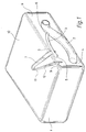
- a fuel tank 1 provided with a filler pipe 2 and a sensing tube 3.
- the filler pipe 2 opens into the fuel tank 1 at an opening 4.
- the sensing tube 3 connects with the fuel tank 1 at an opening 5 and with the filler pipe 2 at an opening 6.
- a barrier 7 which, in plan, is U-shaped.
- the barrier 7 extends from a side surface 11 of the fuel tank to the centre of the tank.
- the barrier 7 is in the form of a continuous wall the upper boundary of which depends from and is integral with the under-side of the top surface 10 of the fuel tank 1.
- the ends 9 of the barrier 7 are integral with the inside of side surface 11 of the fuel tank 1.
- the ullage space of tank 1 is defined by the depth and shape of barrier 7 but as will be discussed later is primarily defined by the depth of the barrier 7 at a point 13 at the centre of a plane parallel with the bottom and/or top of the tank.
- Figure I The essential features of Figure I are also shown on Figures II, III and IV but additionally these Figures illustrate how the design of the enclosure formed by barrier 7 in the fuel tank regulates the ullage space.
- Figure IV shows that the lower edge 12 of barrier 7 is designed to be horizontal at the anticipated maximum degree of tilt of the fuel tank.
Landscapes
- Engineering & Computer Science (AREA)
- Life Sciences & Earth Sciences (AREA)
- Sustainable Development (AREA)
- Sustainable Energy (AREA)
- Chemical & Material Sciences (AREA)
- Combustion & Propulsion (AREA)
- Transportation (AREA)
- Mechanical Engineering (AREA)
- Cooling, Air Intake And Gas Exhaust, And Fuel Tank Arrangements In Propulsion Units (AREA)
Applications Claiming Priority (2)
| Application Number | Priority Date | Filing Date | Title |
|---|---|---|---|
| GB9021247 | 1990-09-29 | ||
| GB9021247A GB2248228A (en) | 1990-09-29 | 1990-09-29 | A fuel tank assembly |
Publications (3)
| Publication Number | Publication Date |
|---|---|
| EP0479523A2 true EP0479523A2 (de) | 1992-04-08 |
| EP0479523A3 EP0479523A3 (en) | 1993-07-28 |
| EP0479523B1 EP0479523B1 (de) | 1995-09-27 |
Family
ID=10682993
Family Applications (1)
| Application Number | Title | Priority Date | Filing Date |
|---|---|---|---|
| EP91308927A Expired - Lifetime EP0479523B1 (de) | 1990-09-29 | 1991-09-30 | Treibstoffbehälter-Anordnung |
Country Status (4)
| Country | Link |
|---|---|
| US (1) | US5251773A (de) |
| EP (1) | EP0479523B1 (de) |
| DE (1) | DE69113383T2 (de) |
| GB (1) | GB2248228A (de) |
Cited By (3)
| Publication number | Priority date | Publication date | Assignee | Title |
|---|---|---|---|---|
| WO1996028316A1 (de) * | 1995-03-13 | 1996-09-19 | Fritz Curtius | Vermeidung von flüssigen emissionen aus fahrzeugen |
| FR3014771A1 (fr) * | 2013-12-16 | 2015-06-19 | Peugeot Citroen Automobiles Sa | Reservoir a degazage lateral et vehicule automobile equipe d'un tel reservoir |
| EP3216641A1 (de) | 2016-03-08 | 2017-09-13 | PSA Automobiles SA | Tank mit entgasungsschlauch |
Families Citing this family (7)
| Publication number | Priority date | Publication date | Assignee | Title |
|---|---|---|---|---|
| US5868179A (en) * | 1997-03-04 | 1999-02-09 | Gilbarco Inc. | Precision fuel dispenser |
| US5749485A (en) * | 1997-05-19 | 1998-05-12 | Chiu; Chun Ta | Portable oil container |
| US6116454A (en) * | 1998-10-01 | 2000-09-12 | Caterpillar Inc. | Hydraulic oil tank with integral baffle |
| US6651764B2 (en) * | 1998-12-23 | 2003-11-25 | Bombardier Inc. | Fuel tank for a recreational vehicle |
| US6712234B2 (en) * | 2000-02-14 | 2004-03-30 | Ti Group Automotive Systems Technology Center Gmbh | Fuel tank and method for its production |
| US20040240204A1 (en) * | 2003-05-29 | 2004-12-02 | Wray Russ | Electric flare |
| US7854345B2 (en) * | 2006-05-24 | 2010-12-21 | Cnh America Llc | Vehicular fuel tank arrangement |
Family Cites Families (16)
| Publication number | Priority date | Publication date | Assignee | Title |
|---|---|---|---|---|
| DE7424653U (de) * | 1974-10-24 | Bayerische Motoren Werke Ag | Kraftstoffbehälter für Kraftfahrzeuge, insbesondere Personenkraftwagen, mit einer Speichereinrichtung | |
| US2172836A (en) * | 1938-02-14 | 1939-09-12 | Lawrence E Gould | Liquid fuel tank |
| DE1175097B (de) * | 1961-10-12 | 1964-07-30 | Daimler Benz Ag | Vorrichtung zur Entlueftung von Kraftstoff-behaeltern, insbesondere fuer Kraftfahrzeuge |
| US3643690A (en) * | 1969-09-13 | 1972-02-22 | Toyota Motor Co Ltd | Vented fuel tank |
| US3687335A (en) * | 1970-11-18 | 1972-08-29 | Chrysler Corp | Overfill limiting apparatus for fuel tanks |
| GB1376530A (en) * | 1971-09-10 | 1974-12-04 | Daimler Benz Ag | Fuel tanks |
| US3838713A (en) * | 1972-10-10 | 1974-10-01 | Tu Co Inc | Trailer tube and connection |
| US3907153A (en) * | 1974-02-19 | 1975-09-23 | Gen Motors Corp | Fuel tank venting system |
| DE2456726B2 (de) * | 1974-11-30 | 1977-03-03 | Daimler-Benz Ag, 7000 Stuttgart | Vorrichtung zur entlueftung von kraftstoffbehaeltern, insbesondere fuer kraftfahrzeuge |
| DE2752645C3 (de) * | 1977-11-25 | 1981-04-09 | Adam Opel AG, 6090 Rüsselsheim | Vorrichtung zur Füllbegrenzung und Be- und Entlüftung bei Behältern, insbesondere Kraftstoffbehältern von Personenkraftwagen |
| US4142647A (en) * | 1977-12-15 | 1979-03-06 | General Motors Corporation | Fuel tank venting system |
| DE2912214C2 (de) * | 1979-03-28 | 1983-02-24 | Daimler-Benz Ag, 7000 Stuttgart | Entlüftungseinrichtung für Kraftstofftanks von Fahrzeugen, insbesondere von Kraftfahrzeugen |
| DE3324329A1 (de) * | 1983-07-06 | 1985-01-17 | Dr.Ing.H.C. F. Porsche Ag, 7000 Stuttgart | Kraftstoffbehaelter fuer kraftfahrzeuge |
| FR2583353B1 (fr) * | 1985-06-14 | 1987-07-24 | Renault | Reservoir a carburant en matiere synthetique, notamment pour vehicule automobile |
| US4874020A (en) * | 1987-03-26 | 1989-10-17 | Whitehead Engineered Products, Inc. | System for controlling the release of fuel vapors from a vehicle fuel tank |
| US4974645A (en) * | 1990-01-09 | 1990-12-04 | Ford Motor Company | Non-expulsive fuel filler assembly |
-
1990
- 1990-09-29 GB GB9021247A patent/GB2248228A/en not_active Withdrawn
-
1991
- 1991-09-27 US US07/766,536 patent/US5251773A/en not_active Expired - Fee Related
- 1991-09-30 DE DE69113383T patent/DE69113383T2/de not_active Expired - Lifetime
- 1991-09-30 EP EP91308927A patent/EP0479523B1/de not_active Expired - Lifetime
Cited By (3)
| Publication number | Priority date | Publication date | Assignee | Title |
|---|---|---|---|---|
| WO1996028316A1 (de) * | 1995-03-13 | 1996-09-19 | Fritz Curtius | Vermeidung von flüssigen emissionen aus fahrzeugen |
| FR3014771A1 (fr) * | 2013-12-16 | 2015-06-19 | Peugeot Citroen Automobiles Sa | Reservoir a degazage lateral et vehicule automobile equipe d'un tel reservoir |
| EP3216641A1 (de) | 2016-03-08 | 2017-09-13 | PSA Automobiles SA | Tank mit entgasungsschlauch |
Also Published As
| Publication number | Publication date |
|---|---|
| DE69113383T2 (de) | 1996-02-29 |
| GB9021247D0 (en) | 1990-11-14 |
| EP0479523B1 (de) | 1995-09-27 |
| US5251773A (en) | 1993-10-12 |
| EP0479523A3 (en) | 1993-07-28 |
| GB2248228A (en) | 1992-04-01 |
| DE69113383D1 (de) | 1995-11-02 |
Similar Documents
| Publication | Publication Date | Title |
|---|---|---|
| EP0597581B1 (de) | Kraftstofftank-Senderanordnung | |
| EP0479523B1 (de) | Treibstoffbehälter-Anordnung | |
| US4261477A (en) | Motor vehicle fuel tank venting device | |
| US6035884A (en) | Liquid fuel baffle for vent apparatus | |
| EP1536968B1 (de) | Kraftstoffbehälter | |
| EP0667253B1 (de) | Brennstoffdampf-Entlüftungseinheit mit Flüssigkeitsfalle | |
| US5265743A (en) | Stackable plastic container | |
| ES2064006T3 (es) | Racor de llenado de deposito de carburante. | |
| US4202386A (en) | Overfill preventive funnel | |
| BRPI0609986A2 (pt) | válvula para um circuito de exaustão de um tanque para lìquido | |
| US6269832B1 (en) | Degassing circuit for liquid tank | |
| GB2082527A (en) | Tank venting device | |
| CA1280980C (en) | Fuel tank for an off-road vehicle | |
| GB2319516A (en) | Fuel tank with venting valve | |
| US3123249A (en) | Venting arrangements for storage tanks | |
| KR101431852B1 (ko) | 액체 탱크의 통기 회로를 위한 밸브 | |
| US5301550A (en) | Float for an automotive liquid level detection device | |
| US4393980A (en) | Liquid container arranged to limit undesirable drainage | |
| CA1207679A (en) | Non spill liquid fuel tanks | |
| CN104154287A (zh) | 用于机动车的装配有通气系统的燃料箱 | |
| US6581621B1 (en) | Valve and fuel tank provided with a valve for a motor vehicle | |
| US6119712A (en) | Float arrangement for liquid containers | |
| US3335896A (en) | Dual-purpose sealer cap | |
| US5979513A (en) | Fuel spillage control apparatus having audible warning | |
| GB2269373A (en) | Anti-trickle arrangement for a vehicle fuel tank |
Legal Events
| Date | Code | Title | Description |
|---|---|---|---|
| PUAI | Public reference made under article 153(3) epc to a published international application that has entered the european phase |
Free format text: ORIGINAL CODE: 0009012 |
|
| AK | Designated contracting states |
Kind code of ref document: A2 Designated state(s): DE FR GB |
|
| PUAL | Search report despatched |
Free format text: ORIGINAL CODE: 0009013 |
|
| AK | Designated contracting states |
Kind code of ref document: A3 Designated state(s): DE FR GB |
|
| 17P | Request for examination filed |
Effective date: 19931208 |
|
| 17Q | First examination report despatched |
Effective date: 19940616 |
|
| GRAA | (expected) grant |
Free format text: ORIGINAL CODE: 0009210 |
|
| PGFP | Annual fee paid to national office [announced via postgrant information from national office to epo] |
Ref country code: FR Payment date: 19950922 Year of fee payment: 5 |
|
| AK | Designated contracting states |
Kind code of ref document: B1 Designated state(s): DE FR GB |
|
| PGFP | Annual fee paid to national office [announced via postgrant information from national office to epo] |
Ref country code: GB Payment date: 19950927 Year of fee payment: 5 |
|
| PGFP | Annual fee paid to national office [announced via postgrant information from national office to epo] |
Ref country code: DE Payment date: 19951012 Year of fee payment: 5 |
|
| REF | Corresponds to: |
Ref document number: 69113383 Country of ref document: DE Date of ref document: 19951102 |
|
| ET | Fr: translation filed | ||
| PLBE | No opposition filed within time limit |
Free format text: ORIGINAL CODE: 0009261 |
|
| STAA | Information on the status of an ep patent application or granted ep patent |
Free format text: STATUS: NO OPPOSITION FILED WITHIN TIME LIMIT |
|
| PG25 | Lapsed in a contracting state [announced via postgrant information from national office to epo] |
Ref country code: DE Effective date: 19960810 |
|
| 26N | No opposition filed | ||
| PG25 | Lapsed in a contracting state [announced via postgrant information from national office to epo] |
Ref country code: GB Effective date: 19960930 Ref country code: FR Effective date: 19960930 |
|
| GBPC | Gb: european patent ceased through non-payment of renewal fee |
Effective date: 19960930 |
|
| REG | Reference to a national code |
Ref country code: FR Ref legal event code: ST |
|
| REG | Reference to a national code |
Ref country code: FR Ref legal event code: ST |