EP0479675A2 - Verfahren und Vorrichtung zum Regeln der Temperatur einer Zerfaserungsscheibe - Google Patents
Verfahren und Vorrichtung zum Regeln der Temperatur einer Zerfaserungsscheibe Download PDFInfo
- Publication number
- EP0479675A2 EP0479675A2 EP91402631A EP91402631A EP0479675A2 EP 0479675 A2 EP0479675 A2 EP 0479675A2 EP 91402631 A EP91402631 A EP 91402631A EP 91402631 A EP91402631 A EP 91402631A EP 0479675 A2 EP0479675 A2 EP 0479675A2
- Authority
- EP
- European Patent Office
- Prior art keywords
- centrifuge
- temperature
- points
- measured
- control method
- Prior art date
- Legal status (The legal status is an assumption and is not a legal conclusion. Google has not performed a legal analysis and makes no representation as to the accuracy of the status listed.)
- Granted
Links
- 238000000034 method Methods 0.000 title claims abstract description 27
- 239000000835 fiber Substances 0.000 title description 11
- 230000001105 regulatory effect Effects 0.000 title 1
- 230000002093 peripheral effect Effects 0.000 claims abstract description 28
- 238000004519 manufacturing process Methods 0.000 claims abstract description 11
- 230000008569 process Effects 0.000 claims abstract description 8
- 239000003365 glass fiber Substances 0.000 claims abstract description 7
- 230000005855 radiation Effects 0.000 claims abstract description 7
- 238000005119 centrifugation Methods 0.000 claims abstract description 6
- 239000002557 mineral fiber Substances 0.000 claims abstract description 3
- 239000011521 glass Substances 0.000 claims description 20
- 238000010438 heat treatment Methods 0.000 claims description 12
- 238000004458 analytical method Methods 0.000 claims description 3
- 230000035945 sensitivity Effects 0.000 claims description 3
- 230000005674 electromagnetic induction Effects 0.000 claims 1
- 239000011491 glass wool Substances 0.000 abstract description 2
- 239000007789 gas Substances 0.000 description 13
- 239000006060 molten glass Substances 0.000 description 9
- 238000012681 fiber drawing Methods 0.000 description 7
- 230000009471 action Effects 0.000 description 5
- 238000005259 measurement Methods 0.000 description 5
- 230000033228 biological regulation Effects 0.000 description 3
- 238000005336 cracking Methods 0.000 description 3
- 230000006378 damage Effects 0.000 description 3
- 238000004031 devitrification Methods 0.000 description 3
- 238000010586 diagram Methods 0.000 description 3
- 239000000203 mixture Substances 0.000 description 3
- 238000013021 overheating Methods 0.000 description 3
- 230000002159 abnormal effect Effects 0.000 description 2
- 238000005266 casting Methods 0.000 description 2
- 238000001816 cooling Methods 0.000 description 2
- 230000007797 corrosion Effects 0.000 description 2
- 238000005260 corrosion Methods 0.000 description 2
- 230000007423 decrease Effects 0.000 description 2
- 230000007547 defect Effects 0.000 description 2
- 230000006698 induction Effects 0.000 description 2
- 230000003287 optical effect Effects 0.000 description 2
- 239000013307 optical fiber Substances 0.000 description 2
- 208000027418 Wounds and injury Diseases 0.000 description 1
- 238000013459 approach Methods 0.000 description 1
- 230000015572 biosynthetic process Effects 0.000 description 1
- 238000007664 blowing Methods 0.000 description 1
- 238000004364 calculation method Methods 0.000 description 1
- 238000012937 correction Methods 0.000 description 1
- 238000001514 detection method Methods 0.000 description 1
- 230000001627 detrimental effect Effects 0.000 description 1
- 238000007599 discharging Methods 0.000 description 1
- 238000006073 displacement reaction Methods 0.000 description 1
- 230000000694 effects Effects 0.000 description 1
- 238000004880 explosion Methods 0.000 description 1
- 239000012530 fluid Substances 0.000 description 1
- 230000004941 influx Effects 0.000 description 1
- 230000000977 initiatory effect Effects 0.000 description 1
- 208000014674 injury Diseases 0.000 description 1
- 238000009413 insulation Methods 0.000 description 1
- 238000002844 melting Methods 0.000 description 1
- 230000008018 melting Effects 0.000 description 1
- 238000012986 modification Methods 0.000 description 1
- 230000004048 modification Effects 0.000 description 1
- 239000012768 molten material Substances 0.000 description 1
- 230000035939 shock Effects 0.000 description 1
- 239000000126 substance Substances 0.000 description 1
- 230000008685 targeting Effects 0.000 description 1
- 230000001960 triggered effect Effects 0.000 description 1
Images
Classifications
-
- C—CHEMISTRY; METALLURGY
- C03—GLASS; MINERAL OR SLAG WOOL
- C03B—MANUFACTURE, SHAPING, OR SUPPLEMENTARY PROCESSES
- C03B37/00—Manufacture or treatment of flakes, fibres, or filaments from softened glass, minerals, or slags
- C03B37/01—Manufacture of glass fibres or filaments
- C03B37/04—Manufacture of glass fibres or filaments by using centrifugal force, e.g. spinning through radial orifices; Construction of the spinner cups therefor
- C03B37/048—Means for attenuating the spun fibres, e.g. blowers for spinner cups
-
- C—CHEMISTRY; METALLURGY
- C03—GLASS; MINERAL OR SLAG WOOL
- C03B—MANUFACTURE, SHAPING, OR SUPPLEMENTARY PROCESSES
- C03B37/00—Manufacture or treatment of flakes, fibres, or filaments from softened glass, minerals, or slags
- C03B37/07—Controlling or regulating
Definitions
- the invention relates to a process for controlling the temperature of a fiberizing plate used during the manufacture of so-called insulating glass fibers.
- the invention also relates to a device specific to the implementation of this method. It applies in particular to the automation of glass wool production lines used mainly in the composition of thermal and / or acoustic insulation products.
- the so-called insulating glass fibers are commonly produced by internal centrifugation, that is to say by introducing a molten glass thread into a centrifuge also called fiberizing plate, rotating at high speed and having at its periphery a very large number of orifices. Under the action of centrifugal force the glass is projected through these orifices in the form of filaments. To the centrifugal force is possibly added a drawing by a gas stream at high temperature and speed, emitted tangentially to the perforated wall of the centrifuge.
- the centrifuge - whose diameter can possibly exceed one meter - is very strongly stressed by constraints of mechanical origin (high speed of rotation) thermal (glass around 1000 C) and chemical (corrosion by glass) .
- the quality of the fibers produced depends very closely on the proper functioning of the centrifuge, that is to say on this good general condition and compliance with the speed and temperature instructions.
- the speed has little reason to be modified by disturbances during manufacture and above all can be completely controlled independently of all the other parameters if one chooses for example to drive the shaft by an asynchronous motor controlled adequately .
- the setpoint given for the speed of rotation can therefore be considered to be strictly observed.
- the temperature of the centrifuge is sensitive to a good number of factors which are, for example, the action of internal burners heating the interior of the centrifuge and additional means of heating, for example by magnetic induction, targeting more particularly the bottom of the centrifuge, the temperature of the glass, the flow rate of the glass, the temperature of the possible gaseous drawing current emitted in the immediate vicinity of the centrifuge or in any case of the more or less hot atmosphere prevailing around the centrifuge, the more or less intense cooling due to the rotation at a greater or lesser speed and the centrifuge itself which can in particular be deformed after a certain period of use and therefore undergo the heating action differently by the burners.
- thermocouples on the internal wall of the centrifuge, to transform the electrical signal received into an electromagnetic wave analyzed by a fixed receiver not attached in rotation of the centrifuge.
- the electrical signal received then serves as a regulation parameter for the annular gas stretch burner placed just around the periphery of the centrifuge.
- the number of points analyzed on the surface of the centrifuge is necessarily limited in relation to the height of the strip and especially in relation to the total length of the circumference of the centrifuge.
- the internal temperature is not always very instructive since its value may in fact be more characteristic of the temperature of the molten glass accumulated in the form of a reserve than of the actual temperature of the centrifuge.
- a thermocouple can detach from the inner wall and then indicate the temperature from a point other than the one it is supposed to analyze.
- the temperature of a centrifuge is not constant over the entire height of the strip, if only because the glass does not always wet it well uniformly; these temperature heterogeneities are therefore considered normal as long as they remain within defined limits and a delocalized measurement, therefore poorly interpreted, can lead to an uncontrolled control of the annular burner.
- the device known from EP-B1-219 433 is especially advantageous during the start-up phase of the fiber drawing, when it is a question of gradually raising the temperature of the centrifuge without creating thermal shocks, the system allowing to be systematically below critical temperatures and to respect the profile well theoretical room heating.
- the fiberizing phase it has been found that it is not always desirable to modify the characteristics of the drawing gas since this then modifies the quality of the fibers produced, the relationship between the temperature of the centrifuge and the temperature of the gases. stretching is not purely unequivocal but involves other parameters such as the deformation of the centrifuge which, for example, heats up as it approaches the burner.
- the temperature of the centrifuge is normally not constant over the entire height of the strip; or if deviations of small amplitude are considered normal, deviations that are too great are on the other hand damaging to the centrifuge itself, and to the quality of the fibers produced insofar as they presuppose abnormal operation of the device.
- the authors of the present invention have set themselves the goal of a new method for controlling a fiber-drawing centrifuge capable of providing information which can be matched with various anomalies of the fiber-drawing process for rapid, manual or automated.
- This object is achieved according to the invention by the fact that during the manufacture of mineral fibers, in particular glass fibers, by a process involving internal centrifugation by means of a centrifuge, the peripheral band of which is pierced with a large number of 'outlet orifices, the radiation emitted from the surface by said peripheral strip is measured in order to determine the temperature of the points of said peripheral strip and the vertical coordinate of each of these corresponding points.
- the first remarkable point of the measured profile corresponds to the hottest point of the perforated part of the peripheral band, which point will later be referred to more briefly as the hottest point, although in many cases the actually hottest point of the centrifuge. is located outside this perforated area where the filaments are formed.
- the hottest point is fixed and determined by the flow conditions of the glass.
- the hottest point is associated with maximum flow.
- This first check is advantageously supplemented by measuring the temperature at the bottom of the peripheral strip.
- the bottom of the centrifuge enters the zone of hot gases emitted by the annular burner, is then heated more significantly by these gases and therefore sees its temperature increased. This rise in temperature is therefore characteristic of significant fatigue of the centrifuge, the replacement of which must then be prepared.
- the temperature at the bottom of the strip decreases appreciably, this means for example a start of devitrification of the glass accumulated at the bottom of the centrifuge and strongly cooled by the cold air present under the centrifuge and intensely stirred due to the rotation. It is then necessary to increase the quantity of heat brought specifically to the bottom of the centrifuge, in particular by a magnetic induction heating device as known for example from patent FR-A-2 443 436.
- the temperature at the top of the peripheral strip, the hottest point above the perforated part is marked on the profile, the abrupt rise of which is characteristic of an anomaly, for example a centrifuge victim of a crack initiation or an off-center annular burner emitting gases directed directly towards the centrifuge and not only at the periphery, while a more gradual variation - possibly associated with an increase in the temperature at the bottom of the strip, is rather an indication of abnormal wear of the centrifuge.
- the invention thus proposes to monitor more particularly three points of the peripheral strip whose coordinates are perfectly determined, but not defined a priori.
- these three points are deduced by calculating the curve derived from the temperature profile, the three measured points corresponding to three extremes of this profile.
- the computer starts from the coordinates of the lowest point to determine those of the highest point, which it is sometimes quite difficult to locate on the temperature profile, but is distant from the lowest point by a distance corresponding exactly to the height of the peripheral strip.
- the operator is warned by a series of alarm indicators of any temperature deviating from the normal therefore corresponding to poor operating conditions, the actions required for a return to normal being triggered either by the operator or fully automated, the latter case being preferred when stopping the casting of molten glass is necessary, in particular for safety reasons.
- the method according to the invention can advantageously be implemented by means of an infrared radiation pyrometer provided with a pivoting optic with a rectangular, long and narrow aiming target, so as to record the radiation of a relatively large surface. without compromising the accuracy of the measurement, a resolution of more than 20 points being preferred.
- the optics of the pyrometer is mounted near the centrifuge, but at a distance nevertheless greater than or equal to 1 meter and the signals are transmitted by an optical fiber to the electronic calculation unit placed at a distance and provided with input devices. / usual output.
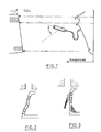
- FIG. 1 is shown on the left the peripheral strip 1, pierced with several thousand outlet orifices 2, of a centrifuge used for the manufacture, for example of glass fibers.
- a centrifuge used for the manufacture, for example of glass fibers.
- the centrifuge is surrounded by the lip of an annular burner 3 which generates a gas stream capable of maintaining around the centrifuge a high temperature.
- the hot distance d which normally separates the top of the periphery band of the centrifuge from the lip of the ring burner is only a few millimeters; any decentering therefore causes a significant disturbance in the heating conditions.
- the centrifuge rotates at high speed and is continuously supplied by a jet of molten glass preferably poured onto a distributor member constituted by a hollow cylindrical body provided with relatively large orifices whose role is to divide the molten material and to direct it under the effect of centrifugal force towards the inner surface of the peripheral strip which it covers and from which it escapes through the multiple orifices 2, in the form of a series of radial filaments.
- the optical part of a pyrometer is placed, the maximum sensitivity of which is preferably for the radiation domain close to infrared, therefore between 0.6 and 1.1 microns .
- This optic is pivotally mounted and scans an angle so as to cover by a continuous movement back and forth the entire height of the peripheral strip.
- the target must have a fairly large surface, preferably of the order of 10 to 50 mm 2 in order to obtain good measurement sensitivity.
- the height of the target must be as small as possible in order to obtain high accuracy as to the vertical coordinates of the measured points. A good compromise is obtained with a rectangular target 1 to 3 mm high and 20 mm wide.
- All the electronics associated with the optical part proper is preferably placed at a great distance, the two parts being connected by an optical fiber if necessary cooled.
- the temperature profile is recorded over the height of the strip.
- This profile has three remarkable points A, B and C corresponding respectively to the highest point of the strip, the hottest point and the coldest point.
- point A does not correspond in all cases to an extremum of the curve but can be found thanks to its vertical coordinate by fixed definition and the positioning of point C, the difference between A and C corresponding to the height of the peripheral strip.
- points B and C are identified by analysis of the derived curve corresponding to the temperature profile.
- the essential point is to avoid local overheating by playing if necessary on the temperature and / or the flow rate of the gases emitted. by the annular burner.
- the regulation is therefore carried out on the basis of point B as indicated in patent EP-B1-219,433.
- a particular case is that of a temperature that is clearly too low at point C, we are then in the situation where it is absolutely necessary to avoid the centrifugation of the centrifuge due to the devitrification of the glass on the bottom of the centrifuge, which bottom is more distant from the lip of the burner and therefore less heated by it but which moreover undergoes cooling by the very fact of rotation by the mixing of air under the centrifuge.
- the additional heating means of the bottom of the centrifuge are therefore controlled by this temperature at point C, this control being facilitated by the fact that electromagnetic inductors are used which therefore react quickly.
- the control of the inductors is preferably controlled for example by stops limiting the frequency settings, because it is known that in practice electromagnetic heating is powerless to unblock a centrifuge if despite all the precautions taken the glass has devitrified, and that 'It is therefore unnecessary or even dangerous to continue this heating further, an inductor set to maximum frequency with nevertheless a too low bottom temperature must therefore immediately stop the casting of molten glass.
Landscapes
- Engineering & Computer Science (AREA)
- Chemical & Material Sciences (AREA)
- Life Sciences & Earth Sciences (AREA)
- General Life Sciences & Earth Sciences (AREA)
- Geochemistry & Mineralogy (AREA)
- Manufacturing & Machinery (AREA)
- Materials Engineering (AREA)
- Organic Chemistry (AREA)
- Manufacture, Treatment Of Glass Fibers (AREA)
- Centrifugal Separators (AREA)
- Treatment Of Fiber Materials (AREA)
- Yarns And Mechanical Finishing Of Yarns Or Ropes (AREA)
- Artificial Filaments (AREA)
- Inorganic Fibers (AREA)
- Chemical Vapour Deposition (AREA)
- Control Of Temperature (AREA)
- Reinforced Plastic Materials (AREA)
- Chemical Or Physical Treatment Of Fibers (AREA)
- Spinning Or Twisting Of Yarns (AREA)
- Glass Compositions (AREA)
- Metal Extraction Processes (AREA)
- Spinning Methods And Devices For Manufacturing Artificial Fibers (AREA)
Applications Claiming Priority (2)
| Application Number | Priority Date | Filing Date | Title |
|---|---|---|---|
| FR9012228A FR2667588B1 (fr) | 1990-10-04 | 1990-10-04 | Procede et dispositif de controle de la temperature d'une assiette de fibrage. |
| FR9012228 | 1990-10-04 |
Publications (3)
| Publication Number | Publication Date |
|---|---|
| EP0479675A2 true EP0479675A2 (de) | 1992-04-08 |
| EP0479675A3 EP0479675A3 (en) | 1992-10-21 |
| EP0479675B1 EP0479675B1 (de) | 1995-05-24 |
Family
ID=9400926
Family Applications (1)
| Application Number | Title | Priority Date | Filing Date |
|---|---|---|---|
| EP91402631A Expired - Lifetime EP0479675B1 (de) | 1990-10-04 | 1991-10-03 | Verfahren und Vorrichtung zum Regeln der Temperatur einer Zerfaserungsscheibe |
Country Status (16)
| Country | Link |
|---|---|
| US (1) | US5259857A (de) |
| EP (1) | EP0479675B1 (de) |
| JP (1) | JPH06340442A (de) |
| KR (1) | KR920007939A (de) |
| AT (1) | ATE123005T1 (de) |
| AU (1) | AU648581B2 (de) |
| BR (1) | BR9104282A (de) |
| CA (1) | CA2052480A1 (de) |
| DE (1) | DE69109993T2 (de) |
| DK (1) | DK0479675T3 (de) |
| ES (1) | ES2075385T3 (de) |
| FI (1) | FI94748C (de) |
| FR (1) | FR2667588B1 (de) |
| NO (1) | NO178840C (de) |
| TR (1) | TR25471A (de) |
| ZA (1) | ZA917604B (de) |
Cited By (2)
| Publication number | Priority date | Publication date | Assignee | Title |
|---|---|---|---|---|
| WO2019012211A1 (fr) * | 2017-07-11 | 2019-01-17 | Saint-Gobain Isover | Assiette de fibrage |
| WO2019175503A1 (fr) | 2018-03-14 | 2019-09-19 | Saint-Gobain Isover | Methode de regulation d'une installation de fibrage |
Families Citing this family (5)
| Publication number | Priority date | Publication date | Assignee | Title |
|---|---|---|---|---|
| GB2257660B (en) * | 1991-05-07 | 1995-03-15 | Ttt Kk | Facsimile apparatus |
| US6408651B1 (en) | 1999-12-30 | 2002-06-25 | Corning Incorporated | Method of manufacturing optical fibers using thermopiles to measure fiber energy |
| US7210314B2 (en) * | 2003-11-07 | 2007-05-01 | Certainteed Corporation | Fiberizer thermocouple support frame |
| FR3078962B1 (fr) * | 2018-03-14 | 2021-10-29 | Saint Gobain Isover | Dispositif pour modifier la temperature d'une assiette de fibrage |
| FR3123647B1 (fr) * | 2021-06-07 | 2023-05-19 | Saint Gobain Isover | Procédé de contrôle d’un dispositif de fibrage |
Family Cites Families (6)
| Publication number | Priority date | Publication date | Assignee | Title |
|---|---|---|---|---|
| DE536137C (de) * | 1929-09-14 | 1931-10-20 | Thomas Felix Aston | Vorrichtung zum UEberziehen von Eiern |
| FR2443436B1 (fr) * | 1978-12-08 | 1989-10-20 | Saint Gobain | Procede de fibrage du verre, dispositif de mise en oeuvre et produits fibres |
| US4392879A (en) * | 1981-09-23 | 1983-07-12 | Owens-Corning Fiberglas Corporation | Method of forming glass fibers while monitoring a process condition in a spinner |
| DE3536137C1 (de) * | 1985-10-10 | 1986-12-18 | Grünzweig + Hartmann und Glasfaser AG, 6700 Ludwigshafen | Verfahren und Vorrichtung zur Herstellung von Fasern aus thermoplastischen Werkstoffen,insbesondere von Glasfasern |
| US4889546A (en) * | 1988-05-25 | 1989-12-26 | Denniston Donald W | Method and apparatus for forming fibers from thermoplastic materials |
| US4861362A (en) * | 1988-05-25 | 1989-08-29 | Denniston Donald W | Method and apparatus for forming fibers from thermoplastic materials |
-
1990
- 1990-10-04 FR FR9012228A patent/FR2667588B1/fr not_active Expired - Fee Related
-
1991
- 1991-09-23 AU AU84662/91A patent/AU648581B2/en not_active Ceased
- 1991-09-24 ZA ZA917604A patent/ZA917604B/xx unknown
- 1991-09-30 CA CA002052480A patent/CA2052480A1/fr not_active Abandoned
- 1991-10-02 JP JP3255264A patent/JPH06340442A/ja active Pending
- 1991-10-02 NO NO913866A patent/NO178840C/no unknown
- 1991-10-03 DK DK91402631.5T patent/DK0479675T3/da active
- 1991-10-03 EP EP91402631A patent/EP0479675B1/de not_active Expired - Lifetime
- 1991-10-03 TR TR91/0987A patent/TR25471A/xx unknown
- 1991-10-03 FI FI914659A patent/FI94748C/fi not_active IP Right Cessation
- 1991-10-03 DE DE69109993T patent/DE69109993T2/de not_active Expired - Fee Related
- 1991-10-03 AT AT91402631T patent/ATE123005T1/de not_active IP Right Cessation
- 1991-10-03 BR BR919104282A patent/BR9104282A/pt not_active Application Discontinuation
- 1991-10-03 ES ES91402631T patent/ES2075385T3/es not_active Expired - Lifetime
- 1991-10-04 KR KR1019910017361A patent/KR920007939A/ko not_active Ceased
- 1991-10-04 US US07/770,932 patent/US5259857A/en not_active Expired - Fee Related
Cited By (7)
| Publication number | Priority date | Publication date | Assignee | Title |
|---|---|---|---|---|
| WO2019012211A1 (fr) * | 2017-07-11 | 2019-01-17 | Saint-Gobain Isover | Assiette de fibrage |
| FR3068963A1 (fr) * | 2017-07-11 | 2019-01-18 | Saint-Gobain Isover | Assiette de fibrage |
| US11505490B2 (en) | 2017-07-11 | 2022-11-22 | Saint-Gobain Isover | Fibre-forming plate |
| EP3652121B1 (de) | 2017-07-11 | 2024-05-01 | Saint-Gobain Isover | Faserbildende platte |
| WO2019175503A1 (fr) | 2018-03-14 | 2019-09-19 | Saint-Gobain Isover | Methode de regulation d'une installation de fibrage |
| FR3078961A1 (fr) * | 2018-03-14 | 2019-09-20 | Saint-Gobain Isover | Methode de regulation d'une installation de fibrage |
| US11613495B2 (en) | 2018-03-14 | 2023-03-28 | Saint-Gobain Isover | Method for controlling a fibre drawing facility |
Also Published As
| Publication number | Publication date |
|---|---|
| ZA917604B (en) | 1992-08-26 |
| AU8466291A (en) | 1992-04-09 |
| FI94748B (fi) | 1995-07-14 |
| BR9104282A (pt) | 1992-06-02 |
| EP0479675B1 (de) | 1995-05-24 |
| FI914659L (fi) | 1992-04-05 |
| FR2667588B1 (fr) | 1993-07-16 |
| CA2052480A1 (fr) | 1992-04-05 |
| FI94748C (fi) | 1995-10-25 |
| FI914659A0 (fi) | 1991-10-03 |
| KR920007939A (ko) | 1992-05-27 |
| DE69109993T2 (de) | 1996-01-11 |
| NO178840B (no) | 1996-03-04 |
| ES2075385T3 (es) | 1995-10-01 |
| TR25471A (tr) | 1993-05-01 |
| AU648581B2 (en) | 1994-04-28 |
| NO178840C (no) | 1996-06-12 |
| NO913866L (no) | 1992-04-06 |
| FR2667588A1 (fr) | 1992-04-10 |
| JPH06340442A (ja) | 1994-12-13 |
| EP0479675A3 (en) | 1992-10-21 |
| DE69109993D1 (de) | 1995-06-29 |
| ATE123005T1 (de) | 1995-06-15 |
| DK0479675T3 (da) | 1995-10-02 |
| NO913866D0 (no) | 1991-10-02 |
| US5259857A (en) | 1993-11-09 |
Similar Documents
| Publication | Publication Date | Title |
|---|---|---|
| EP0479675B1 (de) | Verfahren und Vorrichtung zum Regeln der Temperatur einer Zerfaserungsscheibe | |
| EP0219433B1 (de) | Verfahren und Vorrichtung zum Herstellen von thermoplastischen Fasern, insbesondere Glasfasern | |
| WO1992019797A1 (fr) | Procede de tirage de cristal unique | |
| EP1112977A1 (de) | Verfahren zum Kühlen einer optischen Faser während des Ziehens | |
| EP0622341B1 (de) | Verfahren und Vorrichtung zum Feststellen der Position eines Strahls aus geschmolzenem Material | |
| CA2054326A1 (fr) | Procede et dispositif de production de fibres par centrifugation interne et application au fibrage de certains verres | |
| FR2731933A1 (fr) | Procede et ensemble de chauffage de lingot | |
| CN212582034U (zh) | 一种单晶炉 | |
| EP0047682A1 (de) | Verfahren und Vorrichtung zur Temperaturregelung einer Glasscheibe in einem Ofen mit mehreren Zellen | |
| EP1201793A1 (de) | Verfahren und vorrichtung zur herstellung von hochqualitativen einkristallen | |
| EP0444534B1 (de) | Verfahren und Apparat zum Schmelzen von organischen Stoffen mit Hilfe von Mikrowellen | |
| FR2663754A1 (fr) | Procede de fabrication d'une fibre optique destinee notamment a la reflectometrie temporelle et fibre optique obtenue par ce procede. | |
| US20030196458A1 (en) | Method for controlling process variables and an optical temperature sensor assembly | |
| KR101333668B1 (ko) | 단결정 성장로의 자동 씨딩시스템 | |
| WO2021019187A1 (fr) | Creuset pour traitement thermique hautes temperatures de pieces massives | |
| FR2518239A1 (fr) | Procede et dispositif de frittage de parois refractaires | |
| AU2022291011A1 (en) | Method for controlling a fiberizing device | |
| EP3765421B1 (de) | Verfahren zur steuerung einer faserzieheinrichtung | |
| EP0495723B1 (de) | Verfahren und Vorrichtung zum Herstellen von Mineralfasern | |
| WO2002083584A1 (fr) | Procede et dispositif de fabrication en continu de fils metalliques gaines de verre | |
| JP6942542B2 (ja) | ガラスの製造方法、レンズの製造方法および溶融装置 | |
| CN113549996A (zh) | 一种单晶炉及用该单晶炉进行直拉单晶稳温工艺 | |
| EP0011564A1 (de) | Verfahren und Vorrichtung zum Regeln der Produktion thermoplastischer Mineralfasern | |
| JP3680357B2 (ja) | ガラス母材の火炎加工装置 | |
| EP0693011A1 (de) | Verfahren und vorrichtung zum giessen einer metallischen hülle auf einer seele |
Legal Events
| Date | Code | Title | Description |
|---|---|---|---|
| PUAI | Public reference made under article 153(3) epc to a published international application that has entered the european phase |
Free format text: ORIGINAL CODE: 0009012 |
|
| AK | Designated contracting states |
Kind code of ref document: A2 Designated state(s): AT BE CH DE DK ES FR GB IT LI NL SE |
|
| PUAL | Search report despatched |
Free format text: ORIGINAL CODE: 0009013 |
|
| AK | Designated contracting states |
Kind code of ref document: A3 Designated state(s): AT BE CH DE DK ES FR GB IT LI NL SE |
|
| 17P | Request for examination filed |
Effective date: 19930208 |
|
| 17Q | First examination report despatched |
Effective date: 19940525 |
|
| GRAA | (expected) grant |
Free format text: ORIGINAL CODE: 0009210 |
|
| AK | Designated contracting states |
Kind code of ref document: B1 Designated state(s): AT BE CH DE DK ES FR GB IT LI NL SE |
|
| REF | Corresponds to: |
Ref document number: 123005 Country of ref document: AT Date of ref document: 19950615 Kind code of ref document: T |
|
| REF | Corresponds to: |
Ref document number: 69109993 Country of ref document: DE Date of ref document: 19950629 |
|
| ITF | It: translation for a ep patent filed | ||
| GBT | Gb: translation of ep patent filed (gb section 77(6)(a)/1977) |
Effective date: 19950821 |
|
| REG | Reference to a national code |
Ref country code: ES Ref legal event code: FG2A Ref document number: 2075385 Country of ref document: ES Kind code of ref document: T3 |
|
| REG | Reference to a national code |
Ref country code: DK Ref legal event code: T3 |
|
| PLBE | No opposition filed within time limit |
Free format text: ORIGINAL CODE: 0009261 |
|
| STAA | Information on the status of an ep patent application or granted ep patent |
Free format text: STATUS: NO OPPOSITION FILED WITHIN TIME LIMIT |
|
| 26N | No opposition filed | ||
| PGFP | Annual fee paid to national office [announced via postgrant information from national office to epo] |
Ref country code: SE Payment date: 19970707 Year of fee payment: 7 |
|
| PGFP | Annual fee paid to national office [announced via postgrant information from national office to epo] |
Ref country code: GB Payment date: 19970729 Year of fee payment: 7 |
|
| PGFP | Annual fee paid to national office [announced via postgrant information from national office to epo] |
Ref country code: DK Payment date: 19970807 Year of fee payment: 7 |
|
| PGFP | Annual fee paid to national office [announced via postgrant information from national office to epo] |
Ref country code: DE Payment date: 19971015 Year of fee payment: 7 |
|
| PGFP | Annual fee paid to national office [announced via postgrant information from national office to epo] |
Ref country code: FR Payment date: 19971017 Year of fee payment: 7 Ref country code: AT Payment date: 19971017 Year of fee payment: 7 |
|
| PGFP | Annual fee paid to national office [announced via postgrant information from national office to epo] |
Ref country code: NL Payment date: 19971024 Year of fee payment: 7 |
|
| PGFP | Annual fee paid to national office [announced via postgrant information from national office to epo] |
Ref country code: BE Payment date: 19971104 Year of fee payment: 7 |
|
| PGFP | Annual fee paid to national office [announced via postgrant information from national office to epo] |
Ref country code: CH Payment date: 19980114 Year of fee payment: 7 |
|
| PG25 | Lapsed in a contracting state [announced via postgrant information from national office to epo] |
Ref country code: GB Free format text: LAPSE BECAUSE OF NON-PAYMENT OF DUE FEES Effective date: 19981003 Ref country code: DK Free format text: LAPSE BECAUSE OF NON-PAYMENT OF DUE FEES Effective date: 19981003 Ref country code: AT Free format text: LAPSE BECAUSE OF NON-PAYMENT OF DUE FEES Effective date: 19981003 |
|
| PG25 | Lapsed in a contracting state [announced via postgrant information from national office to epo] |
Ref country code: SE Free format text: LAPSE BECAUSE OF NON-PAYMENT OF DUE FEES Effective date: 19981004 |
|
| PGFP | Annual fee paid to national office [announced via postgrant information from national office to epo] |
Ref country code: ES Payment date: 19981016 Year of fee payment: 8 |
|
| PG25 | Lapsed in a contracting state [announced via postgrant information from national office to epo] |
Ref country code: LI Free format text: LAPSE BECAUSE OF NON-PAYMENT OF DUE FEES Effective date: 19981031 Ref country code: CH Free format text: LAPSE BECAUSE OF NON-PAYMENT OF DUE FEES Effective date: 19981031 Ref country code: BE Free format text: LAPSE BECAUSE OF NON-PAYMENT OF DUE FEES Effective date: 19981031 |
|
| BERE | Be: lapsed |
Owner name: ISOVER SAINT-GOBAIN Effective date: 19981031 |
|
| PG25 | Lapsed in a contracting state [announced via postgrant information from national office to epo] |
Ref country code: NL Free format text: LAPSE BECAUSE OF NON-PAYMENT OF DUE FEES Effective date: 19990501 |
|
| GBPC | Gb: european patent ceased through non-payment of renewal fee |
Effective date: 19981003 |
|
| REG | Reference to a national code |
Ref country code: CH Ref legal event code: PL |
|
| EUG | Se: european patent has lapsed |
Ref document number: 91402631.5 |
|
| PG25 | Lapsed in a contracting state [announced via postgrant information from national office to epo] |
Ref country code: FR Free format text: LAPSE BECAUSE OF NON-PAYMENT OF DUE FEES Effective date: 19990630 |
|
| NLV4 | Nl: lapsed or anulled due to non-payment of the annual fee |
Effective date: 19990501 |
|
| REG | Reference to a national code |
Ref country code: FR Ref legal event code: ST |
|
| PG25 | Lapsed in a contracting state [announced via postgrant information from national office to epo] |
Ref country code: DE Free format text: LAPSE BECAUSE OF NON-PAYMENT OF DUE FEES Effective date: 19990803 |
|
| PG25 | Lapsed in a contracting state [announced via postgrant information from national office to epo] |
Ref country code: ES Free format text: LAPSE BECAUSE OF NON-PAYMENT OF DUE FEES Effective date: 19991004 |
|
| REG | Reference to a national code |
Ref country code: DK Ref legal event code: EBP |
|
| REG | Reference to a national code |
Ref country code: ES Ref legal event code: FD2A Effective date: 20001113 |
|
| PG25 | Lapsed in a contracting state [announced via postgrant information from national office to epo] |
Ref country code: IT Free format text: LAPSE BECAUSE OF NON-PAYMENT OF DUE FEES Effective date: 20051003 |