EP0479710B1 - Fully automatic manufacturing machine, preferably for the manufacturing of shoes - Google Patents
Fully automatic manufacturing machine, preferably for the manufacturing of shoes Download PDFInfo
- Publication number
- EP0479710B1 EP0479710B1 EP19910610084 EP91610084A EP0479710B1 EP 0479710 B1 EP0479710 B1 EP 0479710B1 EP 19910610084 EP19910610084 EP 19910610084 EP 91610084 A EP91610084 A EP 91610084A EP 0479710 B1 EP0479710 B1 EP 0479710B1
- Authority
- EP
- European Patent Office
- Prior art keywords
- forming tool
- parts
- clamping jaws
- fully automatic
- cylinder
- Prior art date
- Legal status (The legal status is an assumption and is not a legal conclusion. Google has not performed a legal analysis and makes no representation as to the accuracy of the status listed.)
- Expired - Lifetime
Links
Images





Classifications
-
- B—PERFORMING OPERATIONS; TRANSPORTING
- B29—WORKING OF PLASTICS; WORKING OF SUBSTANCES IN A PLASTIC STATE IN GENERAL
- B29D—PRODUCING PARTICULAR ARTICLES FROM PLASTICS OR FROM SUBSTANCES IN A PLASTIC STATE
- B29D35/00—Producing footwear
- B29D35/0009—Producing footwear by injection moulding; Apparatus therefor
- B29D35/0018—Moulds
- B29D35/0027—Last constructions; Mountings therefor
-
- A—HUMAN NECESSITIES
- A43—FOOTWEAR
- A43D—MACHINES, TOOLS, EQUIPMENT OR METHODS FOR MANUFACTURING OR REPAIRING FOOTWEAR
- A43D119/00—Driving or controlling mechanisms of shoe machines; Frames for shoe machines
-
- B—PERFORMING OPERATIONS; TRANSPORTING
- B29—WORKING OF PLASTICS; WORKING OF SUBSTANCES IN A PLASTIC STATE IN GENERAL
- B29D—PRODUCING PARTICULAR ARTICLES FROM PLASTICS OR FROM SUBSTANCES IN A PLASTIC STATE
- B29D35/00—Producing footwear
- B29D35/0054—Producing footwear by compression moulding, vulcanising or the like; Apparatus therefor
- B29D35/0063—Moulds
- B29D35/0072—Last constructions; Mountings therefor
Definitions
- the invention relates to a fully automatic manufacturing machine having several processing stations, preferably for the manufacturing of shoes, wherein each of the processing stations comprises at least one processing station bottom plate and at least one pair of outer clamping jaws wholly and partially enclosing an inner forming tool made of at least three parts.
- the tool changing time should be about 5 seconds. This is not possible with the present clamping means even if the operator is fast in manually mounting and clamping the forming tool parts.
- US-A-3,350,748 discloses a quick change mold assembly which is used in a machine for high volume production of shoes. This assembly is rather complex.
- the side mold members have to be positioned and fastened in the assembly one by one and by purely mechanical means. Pneumatic or hydraulic means are not used for clamping the mold members.
- the fully automatic manufacturing machine according to the invention is characterised in the features stated in the characterising portion of claim 1.
- a given forming tool may be quickly fixed to or dismounted from the outer clamping jaws, thereby allowing a fast individual production with short cycle times.
- parts of the inner forming tool may be locked to the clamping jaws by means of at least one pneumatic or hydraulic cylinder placed on the clamping jaws.
- the locking may take place between the individual clamping jaw and the individual forming tool part by means of an eccentric mechanism moved by the pneumatic or hydraulic clamping cylinder.
- clamping jaws may form part of a rotary attachment assembly with a fixed number, preferably 24-30, processing positions, the inner forming tools being mounted individually as regards type, size and kind.
- a tool storing device may be provided for the inner forming tools, from which the forming tools may be mounted in and dismounted from the rotary attachment assembly, thereby allowing a systematic change of tools.
- the dismounting and mounting of the inner forming tools may advantageously take place via a mounting and/or dismounting table.
- the dismounting and mounting of the inner forming tools may take place automatically. As a result, no persons need to be involved in the change of tools per se. Short cycle times easily might cause a very stressed work situation resulting in many potential errors.
- Fig. 1A the outer clamping jaws 11, 12 are seen. There is a right and a left jaw. Between them a cylinder 16 for clamping the sole form part 18 is placed, that is a cylinder mounted from below the portion of the inner forming tool, forming the sole. Between the two clamping jaws some dotted lines are seen, showing two forming tool parts. The clamping jaws are in their "open" position and shown in full line.
- Figs. 1A and 1C it is seen how the outer jaws 11, 12 are drawn apart.
- the dotted line shows the inner forming tool in a closed position and also shows the grip of the jaws around the forming tool parts when the latter are closed on the sole form part per se.
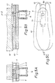
- the sole form part 18 (Fig. 5 B) is placed on the shoe shaped portion 40 in the middle and it is a plate accomodating and forming the basis of the grip of the sole form part, said plate 40 being capable of moving up and down on the bottom plate 5 which supports it.
- said sole form has hitherto been placed in the machine manually and fastened by means of conventional screws.
- the machine into which it is mounted forms part of a large arrangement - a rotary attachment assembly.
- Said rotary attachment assembly comprises a plurality of units, 24-30, moving around a large circle.
- the time it takes to change the inner forming tool parts is important for keeping the cycles times. It takes too long to fasten the forms manually. It was therefore desirable to find a solution whereby the forming tool parts can be pushed in one block - that is folded up around each other - with the clamping jaws "open” into the machine and then the clamping jaws close around the forming tool parts while at the same time the fixing is carried out by means of the clamping cylinder arrangement 26, 27 seen in Fig. 1B.
- the cylinder 26 has some arms 26a with rounded ends 42, 44 (eccentric portions).
- the cylinder 26 presses through the wedges 46, 48 the forming tool against the plate 40 by turning the arms 26a of the eccentric portions towards the skew blocks 46, 48. Opening/closing of the tool takes place by pins 34 holding the cylinder arrangement 26, 27. These pins are fastened as shown in Fig. 1A with a centre of rotation in the clamping jaws. In this manner, the circular portion 41 - clearly shown in a trapezoid shape in Fig. 1A - abuts corresponding skew blocks at the bottom, said blocks having a shape adapted thereto. Thereby the outer forming tool parts are caused to abut the plate 40 and to be fastened and follow the clamping jaws when they "open".
- the technique of the invention may also be used in corresponding machinery, for instance for moulding plastic parts.
- corresponding machinery for instance for moulding plastic parts.
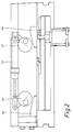
- Figs. 2 and 3 show a clamping cylinder device (on a large scale), the forming tool parts being in an open position.
- the height of the wedging blocks 46, 48 is not larger than to allow the blocks to be wedged under the clamping cylinder device.
- the cylinder 16 mentioned above which services for clamping the sole form part 18 has a bolt with a conventional cylindrical head 6 (bolt head) at its piston rod end. This head engages with a plate mounted at the bottom side of the sole form, said plate being provided with a T-shaped slot 8.
- the plate shown in Fig. 5 and which has a slot being T-shaped in cross-section is mounted at the bottom of the sole form 18 by means of a single screw.
- the plate In order to get space for the plate on the sole form part 18, the plate is placed in a milling formed in a mounting plate 40 of the sole form part. Said milling is made in such a manner that there is also space for the bolt head 6.
- the cylinder 16 fastens the sole form part in a certain level.
- the sole form part is, however, able to move over the bolt head 6.
- the height of the sole form part 18 is adjustable in the forming tool so that for instance a shoe sole may be moulded with two different plastic masses, two different colours and different consistency etc.
- the forming tool parts consist of three forming tools it is essential to have a mouting and/or dismounting table 50, conf. Fig. 6A, arranged in front of the machine.
- the machine shown is a fully automatic rotary attachment machine, conf. Fig. 4.
- the table 50 may be provided with a scissors-shaped support so that it may keep its horizontal position during the adjustment.
- a ruler is provided which cooperates with some rolls on the mounting table.
- the inlet side of said rulers is pointed to ensure that it easily adapts to the rolls.
- the rolls are arranged on axle journals on the table 50 in such a way that when the rotary table moves to the mounting table 50, each ruler contacts these rollers, and the table 50 will be raised/lowered to the correct position.
- the machine has a frame supporting the table 29 mentioned above, said table supporting said pair of outer clamping jaws. Furthermore, the table of the machine is provided with an opening in vertical direction wherein said mounting plate 40 for the third form part of the tool, the sole form, has been placed.
- the mounting plate 40 is placed in a vertical position in a suitable height during the production of the shoe.
- a groove 52 is provided to accomodate a C-profile portion 54 facing downwards from the sole form part, thereby ensuring that said sole form part fixed between the two outer forming tool parts may be introduced into the machine without any turning in relation to the longitudinal direction.
- the correct direction is further ensured by the fact that the forming tool during the introduction is made to abut a bottom stop provided on each of the outer clamping jaws, which the tool hits.
- the C-profile portion and a pin placed in front of the C-profile portion will be guided into the groove 52 of the mounting plate, which groove is provided with a tapering 53 at its front end, which the downward facing pin portion of the sole tools runs into.
- the C-profile portion is placed so that it catches the bolt head 6 of the cylinder 16.
- Final clamping of the forming tool parts take place by the fact that cylinder 16 moves the bolt head 6 which in turn clamps the two downward facing web portions of the C-profile portion 54.
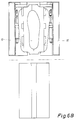
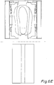
- Figs. 6A-6E The outer clamping jaws in the machine are open which is the starting situation when introducing the forming tool (Fig. 6A). Subsequently the outer clamping jaws are moved towards each other, conf. Fig. 6B.
- the arm parts 26a simultaneously slide over the wedge-shaped parts 46, 48.
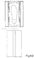
- the clamping cylinder 26,27 is first in a position corresponding to "open” (Fig. 6C), but is then moved to a position corresponding to "closed forming tools”. Simultaneoulsy, the eccentric portions 42, 44 press on the wedge blocks 46,48 so that the two outer forming tool parts and the sole form part as well are fixed in relation to the outer clamping jaws 11, 12.
- the bolt head 6 which is arranged below in the T-shaped slot then locks the sole form part. This is done by means of the clamping cylinder 16.
- the forming tool comprises three parts, of which the middle part must be displacable in vertical direction in relation to the two outer forming tool parts. It is desired to prevent mutual displacement of the forming tool parts when said form parts are placed on the mounting table.
- All cylinders are under pressure during the fixing of the forming tool, said pressure being controlled by means of a central control unit of the machine. This applies both to the clamping cylinders 26,27 and the cylinder 16.
- the cycle is simple: open forming tool, push in the tool into the processing station, whereupon the outer clamping jaws clamp the forming tool parts and when they give off a signal indicating that the clamping jaws are in closed position, pressure is provided to the clamping cylinders 26,27 and the cylinder 16.
- the forming tool may now open and close and the sole form part may be moved up and down during the remaining part of the moulding process.
- the shape of the plate part which has a T-slot and which is fastened by screws to the under surface of the sole form part has been chosen to allow a bolt head to fasten the forming tool parts correctly so that when the outer forming tool parts are clampled around the sole form part, the outer forming tool parts are placed accurately.
Landscapes
- Engineering & Computer Science (AREA)
- Mechanical Engineering (AREA)
- Moulds For Moulding Plastics Or The Like (AREA)
- Footwear And Its Accessory, Manufacturing Method And Apparatuses (AREA)
Applications Claiming Priority (2)
| Application Number | Priority Date | Filing Date | Title |
|---|---|---|---|
| DK239290A DK172201B1 (da) | 1990-10-03 | 1990-10-03 | Fremstillingsautomat med flere bearbejdningsstationer |
| DK2392/90 | 1990-10-03 |
Publications (3)
| Publication Number | Publication Date |
|---|---|
| EP0479710A2 EP0479710A2 (en) | 1992-04-08 |
| EP0479710A3 EP0479710A3 (en) | 1992-11-25 |
| EP0479710B1 true EP0479710B1 (en) | 1996-06-19 |
Family
ID=8112058
Family Applications (1)
| Application Number | Title | Priority Date | Filing Date |
|---|---|---|---|
| EP19910610084 Expired - Lifetime EP0479710B1 (en) | 1990-10-03 | 1991-10-02 | Fully automatic manufacturing machine, preferably for the manufacturing of shoes |
Country Status (3)
| Country | Link |
|---|---|
| EP (1) | EP0479710B1 (da) |
| DE (1) | DE69120365T2 (da) |
| DK (1) | DK172201B1 (da) |
Families Citing this family (2)
| Publication number | Priority date | Publication date | Assignee | Title |
|---|---|---|---|---|
| CN109866447A (zh) * | 2019-04-16 | 2019-06-11 | 鄂州市源通塑胶机械有限责任公司 | 一种新型连帮注塑鞋用旋转式自动装卸楦头装置及方法 |
| CN119305117B (zh) * | 2024-09-12 | 2025-08-12 | 杭州鸿旷机械有限公司 | 一种泡沫鞋底成型注塑模具成型设备 |
Family Cites Families (4)
| Publication number | Priority date | Publication date | Assignee | Title |
|---|---|---|---|---|
| US3350748A (en) * | 1965-07-27 | 1967-11-07 | United Shoe Machinery Corp | Quick change mold assemblies |
| DE1629746A1 (de) * | 1967-04-21 | 1971-02-04 | Desma Werke Gmbh | Spritzgiessanlage mit auswechselbaren Spritzgiessformen |
| DK156693C (da) * | 1984-11-06 | 1990-03-05 | Eccolet Sko As | Anlaeg til paastoebning af saaler paa skoskafter |
| KR900007341B1 (ko) * | 1987-04-16 | 1990-10-08 | 가부시기가이샤 싱고 세루 빅구 | 수지 성형용 카세트형 금형 |
-
1990
- 1990-10-03 DK DK239290A patent/DK172201B1/da not_active IP Right Cessation
-
1991
- 1991-10-02 EP EP19910610084 patent/EP0479710B1/en not_active Expired - Lifetime
- 1991-10-02 DE DE1991620365 patent/DE69120365T2/de not_active Expired - Fee Related
Also Published As
| Publication number | Publication date |
|---|---|
| DK239290D0 (da) | 1990-10-03 |
| DE69120365T2 (de) | 1996-10-31 |
| DK172201B1 (da) | 1998-01-05 |
| EP0479710A3 (en) | 1992-11-25 |
| EP0479710A2 (en) | 1992-04-08 |
| DK239290A (da) | 1992-06-04 |
| DE69120365D1 (de) | 1996-07-25 |
Similar Documents
| Publication | Publication Date | Title |
|---|---|---|
| US4988261A (en) | Multiple motion transfer apparatus | |
| EP0393474B1 (en) | Quilting machine with stationary cloth-holder frame and sewing heads movable in orthogonal directions | |
| US3546990A (en) | Method and apparatus for die cutting blanks from stacks of sheet material | |
| US6354581B1 (en) | Mechanism for clamping and holding an elongated workpiece | |
| CA2023160C (en) | Apparatus for stripping molded rubber products from a product sheet | |
| GB2284379A (en) | Loader basket assembly for tire press | |
| US4718339A (en) | Press with chucking plates for sets of tools | |
| CN104526380B (zh) | 一种可夹持弧形板的夹具 | |
| CA1233623A (en) | Apparatus for the handling of metal sheets | |
| EP0479710B1 (en) | Fully automatic manufacturing machine, preferably for the manufacturing of shoes | |
| JPS6387211A (ja) | 型閉鎖装置組立体 | |
| KR930007659B1 (ko) | 평판재의 위치 결정장치 | |
| US4498328A (en) | Press device | |
| KR102446815B1 (ko) | 대형 제품 가공보조용 로딩지그시스템 | |
| US3460226A (en) | Die set manipulator | |
| US4795334A (en) | Concrete block molding machine | |
| US3583270A (en) | Slitters for travelling webs | |
| GB2124541A (en) | Mechanism for exchanging molding dies in an injection molding machine | |
| US4104962A (en) | Press | |
| JPH079451A (ja) | 金型組立装置及び金型製作方法 | |
| US4741380A (en) | Combined mold assembly and inspection device for core and shell shooters | |
| US4729232A (en) | Machines for pressure forming surface configurations on a rotary workpiece | |
| EP0124845A1 (en) | Device for positioning an machining unit relatively to a workpiece, in particular for transfer lines | |
| CN115027066A (zh) | 一种液压软管扣压机 | |
| EP1149643B1 (en) | Device for forming a profiled edge on one end of a tubular member |
Legal Events
| Date | Code | Title | Description |
|---|---|---|---|
| PUAI | Public reference made under article 153(3) epc to a published international application that has entered the european phase |
Free format text: ORIGINAL CODE: 0009012 |
|
| AK | Designated contracting states |
Kind code of ref document: A2 Designated state(s): DE IT |
|
| PUAL | Search report despatched |
Free format text: ORIGINAL CODE: 0009013 |
|
| AK | Designated contracting states |
Kind code of ref document: A3 Designated state(s): DE IT |
|
| 17P | Request for examination filed |
Effective date: 19930521 |
|
| 17Q | First examination report despatched |
Effective date: 19941115 |
|
| GRAH | Despatch of communication of intention to grant a patent |
Free format text: ORIGINAL CODE: EPIDOS IGRA |
|
| GRAH | Despatch of communication of intention to grant a patent |
Free format text: ORIGINAL CODE: EPIDOS IGRA |
|
| GRAA | (expected) grant |
Free format text: ORIGINAL CODE: 0009210 |
|
| ITF | It: translation for a ep patent filed | ||
| AK | Designated contracting states |
Kind code of ref document: B1 Designated state(s): DE IT |
|
| REF | Corresponds to: |
Ref document number: 69120365 Country of ref document: DE Date of ref document: 19960725 |
|
| PLBE | No opposition filed within time limit |
Free format text: ORIGINAL CODE: 0009261 |
|
| 26N | No opposition filed | ||
| PGFP | Annual fee paid to national office [announced via postgrant information from national office to epo] |
Ref country code: DE Payment date: 20011218 Year of fee payment: 11 |
|
| PG25 | Lapsed in a contracting state [announced via postgrant information from national office to epo] |
Ref country code: DE Free format text: LAPSE BECAUSE OF NON-PAYMENT OF DUE FEES Effective date: 20030501 |
|
| PG25 | Lapsed in a contracting state [announced via postgrant information from national office to epo] |
Ref country code: IT Free format text: LAPSE BECAUSE OF NON-PAYMENT OF DUE FEES;WARNING: LAPSES OF ITALIAN PATENTS WITH EFFECTIVE DATE BEFORE 2007 MAY HAVE OCCURRED AT ANY TIME BEFORE 2007. THE CORRECT EFFECTIVE DATE MAY BE DIFFERENT FROM THE ONE RECORDED. Effective date: 20051002 |