EP0479768A2 - Méthode pour la gestion de canaux radio - Google Patents
Méthode pour la gestion de canaux radio Download PDFInfo
- Publication number
- EP0479768A2 EP0479768A2 EP91890233A EP91890233A EP0479768A2 EP 0479768 A2 EP0479768 A2 EP 0479768A2 EP 91890233 A EP91890233 A EP 91890233A EP 91890233 A EP91890233 A EP 91890233A EP 0479768 A2 EP0479768 A2 EP 0479768A2
- Authority
- EP
- European Patent Office
- Prior art keywords
- data
- radio channels
- center
- transmission
- transmission path
- Prior art date
- Legal status (The legal status is an assumption and is not a legal conclusion. Google has not performed a legal analysis and makes no representation as to the accuracy of the status listed.)
- Granted
Links
Images


Classifications
-
- H—ELECTRICITY
- H04—ELECTRIC COMMUNICATION TECHNIQUE
- H04J—MULTIPLEX COMMUNICATION
- H04J3/00—Time-division multiplex systems
- H04J3/02—Details
- H04J3/12—Arrangements providing for calling or supervisory signals
- H04J3/125—One of the channel pulses or the synchronisation pulse is also used for transmitting monitoring or supervisory signals
-
- H—ELECTRICITY
- H04—ELECTRIC COMMUNICATION TECHNIQUE
- H04W—WIRELESS COMMUNICATION NETWORKS
- H04W88/00—Devices specially adapted for wireless communication networks, e.g. terminals, base stations or access point devices
- H04W88/08—Access point devices
Definitions
- the invention relates to a method for the management of radio channels, in which the data of a center are transmitted via at least one sub-center and from this via transmitting or receiving units and the radio channels to mobile stations or vice versa, and the voice data and the signaling data for the transmission - and receiving units of the individual radio channels are managed by a line management system.
- radio-based communication such as is used in air traffic control systems
- several radio channels are managed by a control center and the necessary transmitters and receivers are controlled.
- the communication channels between the head office and the transmitting and receiving stations are formed by telephone lines, coax lines or radio links.
- a transmission path for voice and alternating current telegraph channels for telecontrol signals for controlling the transmitter and receiver are required for each radio channel. Since the reliability of such transmission lines is not particularly great, especially when using directional radio links, and on the other hand the reliability of the overall system is an important system feature, additional reserve line routes must be provided, which can replace a failed regular transmission route at short notice. Due to the reserve and the large number of transmission paths that are always available, the operating costs for such a communication system are very high.
- the aim of the invention is therefore to reduce the effort for the fail-safe connection of the control center to a sub-control center.
- FIG. 1 shows a typical structure of a communication system with radio channels.
- a center 1 receives messages to be transmitted in M radio channels via directly connected workplaces, switching systems, telephone connections or further radio links, with additional signaling information (squelch, PTT, AGC, etc.) also having to be transmitted in addition to the voice data.
- the voice data and signaling data of each radio channel are to generally mobile stations 15, such as communication partners, such as Airplanes.
- each radio channel is continuously transmitted to the receiver via its own transmission path, but rather that several, namely N radio channels are transmitted between the center and a sub-control center to the sub-control center 2 using the time division multiplex method, pulse code modulated.
- N is contained in M and, if appropriate, a sub-center for the "divisional remainder".
- the output data of the sub-center 2 are transmitted to a transmitting station 3, the transmission to the mobile stations 15 taking place via radio-based communication.
- Each transmission path 7 from the center to a sub-center has a transmission capacity X.
- the transmission capacity is 64 kbit / sec.
- the local connection from the sub-center to the transmitter 3 is generally through an analog transmission path in the baseband, e.g. a telephone line.
- a telecontrol center 5 can also be connected to the control center 1, the telecontrol information also being transmitted via the transmission paths 7 to the respective sub-control centers 2, to each of them a telecontrol subcentral 6 is connected, in which the telecontrol commands are evaluated.
- both the control center 1 and each sub-control center 2 each have a line management unit 8, 9.
- the invention is not limited to such a transmission path.
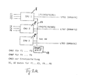
- FIG. 2a shows line management units 8, 8 ', 8 "of the center, this arrangement differing from that on the part of the sub-centers only in that inputs of line management units 8 correspond to the central outputs of line management units 9 of sub-center 2 and outputs of the central inputs
- the lines since duplex operation is required for each connection in general, according to the state of the art, the lines must either be operated bidirectionally or physically consist of two parallel line strings, each with simplex operation. This is not essential for the function of the line management system according to the invention and will therefore not explained further.
- the center comprises, for example, three line management units 8, 8 ', 8 ", each of which operates a line LTG1, LTG2, LTG3. These lines correspond to the transmission paths 7 in FIG. 1 and each have a total transmission capacity of 64 kbit / sec .
- the signals of the radio channels f1 to f3 are present at the inputs of the line management unit 8, and signals of the radio channels f4 to f6 are present at the inputs of the line management unit 8 '.
- the line management unit 8 is used in the described embodiment as a reserve unit for equivalent circuits.
- the three line management units are furthermore connected to one another via an internal PCM cascading highway (14), to which a CODEC unit 13 is also connected.
- the data (signaling, control data such as squelch, push-to-talk, AGC) for the three radio channels f1 to f3 and further telecontrol information are transmitted in a multiplex data channel D1.
- 4 channels namely three radio channels f1, f2, f3 and one data channel D1, each with a data rate of 16 kbit / sec, are transmitted on the line LTG1 using pulse code modulation in time division multiplex.
- the radio channels f4 to f6 are connected to the line management unit 8 'and, together with the data channel D2 assigned to them, are transmitted in time-division multiplex via the line LTG2 in pulse code modulation.
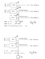
- FIG. 2b schematically shows how, in a further embodiment of the invention, the failure of a line, the failure of the line LTG1 is shown by substituting lines.
- the time-division multiplex signal originally provided for the line LTG1, consisting of the radio channels f1 to f3 and the data channel D1 is controlled by the CODEC unit 13 via transfer the internal cascading highway 14 to the line management unit 8 ′′, which transmits it via the replacement line LTG3.
- the three radio channels f4, f5, f6 and data channel D2 are transmitted as before via line LTG2, the additional services originally transmitted on line LTG3, such as the service telephone, are reset.
- 3 shows the situation in line management units when different priorities can be assigned to the individual radio channels.
- 3a shows a system for transmitting 6 radio channels via two line management units 8, 8 'in an analogous manner to that described in FIG. 2a. In this case too, more than two lines and line management units could be provided without restrictions.
- the radio channels f1 to f3 and the assigned data channel D1 are transmitted via the line LTG1, the radio channels f4 to f6 and the data channel D2 via the line LTG2.
- the radio channels f1 and f4 represent very important channels, that is to say that they also have to be transmitted in the event of a line break, the other radio channels f2, f3 and f5, f6 should be less important, ie, they may fail in the event of a line fault.
- 3b shows schematically how the failure of the line LTG2 is compensated for using a modified method according to the invention, namely the equivalent switching of channels. The less important radio channels of the undisturbed line are switched off and the important channels are transmitted in the slots of the transmission capacity that are freed up as a result.
- the line management unit 8 clears the third capacity slot of its line LTG1 and transmits the important radio channel f4 instead of the originally intended, less important radio channel f3, whereby - controlled by the CODEC unit - its data from the line management unit 8 'via the cascading highway 14 to the Line management unit 8 are supplied.
- the data channel D1 is modified such that the data of the radio channel f4 is transmitted instead of the data for the radio channel f3 that is no longer required.
- all the important radio channels (f1 and f4) with their associated data (in D1 and D2) and additionally one of the less important channels (f2) are transmitted; this means that the remaining transmission capacity is optimally used.
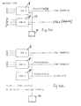
- FIGS. 4 a and 4 b This is to be shown using an example in FIGS. 4 a and 4 b.
- the normal operation of the system corresponds to that of Fig. 2a.
- Three line management units 8, 8 ', 8 "operate three lines LTG1 to LTG3, the first two line management units being assigned three radio channels f1 to f3 and f4 to f6, respectively.
- the third line management unit manages the replacement line LTG3 and transmits additional services via it in normal operation, such as service telephone etc.
- the radio channels f1 and f4 should again represent very important channels, the other channels (f2, f3, f5, f6) should be less important.
- 4 a shows the behavior of the system in the event of a failure of a first line, a failure of the line LTG1 being assumed. Since the system still has a reserve line (LTG3) available, the method of line replacement switching is selected and the radio channels (f1 to f3) and data (D1) provided for the line LTG1 are controlled by the CODEC unit 13 via the cascading highway 14 the line management unit 8 "and further transmitted via the spare line LTG3. If another line, for example LTG2, fails if the line LTG1 has failed, then the method of the channel equivalent circuit is selected, since no further reserve line is available.
- LTG3 reserve line
- the one via the spare line The less important radio channel f3 which is also transmitted with LTG3 is disconnected and the important radio channel f4 originally intended for the now disturbed line LTG2 is transmitted in its place, and its data is also transmitted in the modified data channel D12. In this way, even the failure of several lines can be avoided can be mastered without failure of an important radio channel.
- the invention is not limited to this; In this way, design variants are also conceivable in which only a part of the transmission paths or only a single one of these transmission paths is operated in the manner according to the invention.
Landscapes
- Engineering & Computer Science (AREA)
- Computer Networks & Wireless Communication (AREA)
- Signal Processing (AREA)
- Mobile Radio Communication Systems (AREA)
- Time-Division Multiplex Systems (AREA)
Applications Claiming Priority (2)
| Application Number | Priority Date | Filing Date | Title |
|---|---|---|---|
| AT0199890A AT398662B (de) | 1990-10-03 | 1990-10-03 | Verfahren zur verwaltung von funkkanälen |
| AT1998/90 | 1990-10-03 |
Publications (3)
| Publication Number | Publication Date |
|---|---|
| EP0479768A2 true EP0479768A2 (fr) | 1992-04-08 |
| EP0479768A3 EP0479768A3 (en) | 1992-11-25 |
| EP0479768B1 EP0479768B1 (fr) | 1997-01-15 |
Family
ID=3525624
Family Applications (1)
| Application Number | Title | Priority Date | Filing Date |
|---|---|---|---|
| EP91890233A Expired - Lifetime EP0479768B1 (fr) | 1990-10-03 | 1991-10-03 | Méthode pour la gestion de canaux radio |
Country Status (3)
| Country | Link |
|---|---|
| EP (1) | EP0479768B1 (fr) |
| AT (2) | AT398662B (fr) |
| DE (1) | DE59108485D1 (fr) |
Cited By (4)
| Publication number | Priority date | Publication date | Assignee | Title |
|---|---|---|---|---|
| EP0617522A3 (fr) * | 1993-03-26 | 1994-11-30 | Siemens Ag | Système de communication pour connexion à une station de base d'un réseau radio cellulaire. |
| FR2719428A1 (fr) * | 1994-04-27 | 1995-11-03 | Trt Telecom Radio Electr | Système de transmission formé au moins d'une station de base, d'une station satellite et d'une station nodale et station de base et station satellite convenant à un tel système. |
| WO1998021841A1 (fr) * | 1996-11-14 | 1998-05-22 | Telefonaktiebolaget Lm Ericsson (Publ) | Procede pour multiplexer des liaisons adjacentes emetteur-recepteur/transcodeur en une seule voie temporelle |
| RU2210189C2 (ru) * | 1996-11-22 | 2003-08-10 | Спринт Коммьюникейшнз Компани, Л.П. | Система и способ для обеспечения усовершенствованных служб для телекоммуникационного вызова |
Family Cites Families (4)
| Publication number | Priority date | Publication date | Assignee | Title |
|---|---|---|---|---|
| EP0168647A3 (fr) * | 1984-07-19 | 1988-07-27 | ANT Nachrichtentechnik GmbH | Système radio-mobile pour la transmission de signaux digitaux |
| US4829554A (en) * | 1985-01-31 | 1989-05-09 | Harris Corporation | Cellular mobile telephone system and method |
| DE3516074A1 (de) * | 1985-05-04 | 1986-11-06 | Philips Patentverwaltung Gmbh, 2000 Hamburg | Dienstintegriertes funkuebertragungssystem |
| DE3579596D1 (de) * | 1985-10-17 | 1990-10-11 | Ant Nachrichtentech | Mobilfunksystem fuer die uebertragung sowohl digitaler als auch analoger signale. |
-
1990
- 1990-10-03 AT AT0199890A patent/AT398662B/de not_active IP Right Cessation
-
1991
- 1991-10-03 DE DE59108485T patent/DE59108485D1/de not_active Expired - Fee Related
- 1991-10-03 AT AT91890233T patent/ATE147912T1/de not_active IP Right Cessation
- 1991-10-03 EP EP91890233A patent/EP0479768B1/fr not_active Expired - Lifetime
Cited By (7)
| Publication number | Priority date | Publication date | Assignee | Title |
|---|---|---|---|---|
| EP0617522A3 (fr) * | 1993-03-26 | 1994-11-30 | Siemens Ag | Système de communication pour connexion à une station de base d'un réseau radio cellulaire. |
| US5617467A (en) * | 1993-03-26 | 1997-04-01 | Siemens Aktiengesellschaft | Communication system for connection to a base station of a multi-cellular wireless telephone system |
| FR2719428A1 (fr) * | 1994-04-27 | 1995-11-03 | Trt Telecom Radio Electr | Système de transmission formé au moins d'une station de base, d'une station satellite et d'une station nodale et station de base et station satellite convenant à un tel système. |
| EP0681407A1 (fr) * | 1994-04-27 | 1995-11-08 | T.R.T. Telecommunications Radioelectriques Et Telephoniques | Système de transmission par multiplexage temporel, entre au moins une station satellite, une station de base et une station nodal |
| WO1998021841A1 (fr) * | 1996-11-14 | 1998-05-22 | Telefonaktiebolaget Lm Ericsson (Publ) | Procede pour multiplexer des liaisons adjacentes emetteur-recepteur/transcodeur en une seule voie temporelle |
| US6018532A (en) * | 1996-11-14 | 2000-01-25 | Telefonaktiebolget L M Ericsson (Publ) | Method for multiplexing adjacent transceiver/transcoder links into a single timeslot |
| RU2210189C2 (ru) * | 1996-11-22 | 2003-08-10 | Спринт Коммьюникейшнз Компани, Л.П. | Система и способ для обеспечения усовершенствованных служб для телекоммуникационного вызова |
Also Published As
| Publication number | Publication date |
|---|---|
| DE59108485D1 (de) | 1997-02-27 |
| ATE147912T1 (de) | 1997-02-15 |
| EP0479768A3 (en) | 1992-11-25 |
| AT398662B (de) | 1995-01-25 |
| EP0479768B1 (fr) | 1997-01-15 |
| ATA199890A (de) | 1994-05-15 |
Similar Documents
| Publication | Publication Date | Title |
|---|---|---|
| EP0008016A1 (fr) | Procédé ainsi que appareil de transmission et réception pour la transmission de données à correctron adaptable des erreurs | |
| EP0017835B1 (fr) | Circuit pour commander la transmission de signaux digitaux, notamment signaux MIC, entre les points de raccordement d'un système de télécommunications à multiplexage par partage du temps, notamment d'un système MIC | |
| EP0110464B1 (fr) | Standard privé | |
| EP0020893B1 (fr) | Réseau radio | |
| EP0618688A2 (fr) | Système pour la transmission de données par radio entre au moins une station mobile et n stations de base fixes ordonnées le long d'un trajet | |
| EP1246150A2 (fr) | Système d'alarme d'incendie | |
| EP0479768B1 (fr) | Méthode pour la gestion de canaux radio | |
| EP0590412A1 (fr) | Système à bus pour la communication et la commande dans une station de base radio | |
| EP0338640B1 (fr) | Réseau de télécommunication à mailles | |
| DE2917978C2 (de) | Kabelkommunikationssystem | |
| EP0966798A2 (fr) | Reseau pour la transmission de paquets de donnees et procede permettant de faire fonctionner ce reseau | |
| EP0560122A2 (fr) | Système de communication avec des stations sur un bus | |
| DE4224422A1 (de) | Relais-Funksystem und Funkgerät dafür | |
| EP0448927A1 (fr) | Procédé de transmission d'informations en temps discret | |
| DE19733765A1 (de) | Verfahren zur Kommunikation zwischen einem im Bereich einer Schienenstrecke angeordneten Feldelement und einer zentralen Überwachungseinheit sowie Kommunikationssystem und Sendeempfangseinheit hierfür | |
| DE2103307A1 (de) | Schaltungsanordnung zur Eingabe von Daten in nicht besetzte Kanäle eines Multiplexsystem | |
| DE69107534T2 (de) | Digitales Kommunikationssystem für eine digitale dienstintegrierte Fernsprechanlage. | |
| DE2124673C3 (de) | Schaltungsanordnung zur Übertragung von Nachrichtenverbindungen zugehörigen, insbesondere durch Schaltkennzeichen gebildeten Datensignalen, über eine PCM-Übertragungsstrecke | |
| DE3329566C2 (fr) | ||
| EP0676906B1 (fr) | Système et méthode pour la transmission de signaux de parole et de service | |
| EP0046846B1 (fr) | Système de communication par câble | |
| DE3822263A1 (de) | Schaltungsanordnung zum uebertragen von informationen | |
| DE1512049B2 (de) | Fernsprechanlage | |
| AT388832B (de) | Kabelkommunikationssystem | |
| EP4498654A1 (fr) | Système de communication |
Legal Events
| Date | Code | Title | Description |
|---|---|---|---|
| PUAI | Public reference made under article 153(3) epc to a published international application that has entered the european phase |
Free format text: ORIGINAL CODE: 0009012 |
|
| AK | Designated contracting states |
Kind code of ref document: A2 Designated state(s): AT BE CH DE DK ES FR GB GR IT LI LU NL SE |
|
| PUAL | Search report despatched |
Free format text: ORIGINAL CODE: 0009013 |
|
| AK | Designated contracting states |
Kind code of ref document: A3 Designated state(s): AT BE CH DE DK ES FR GB GR IT LI LU NL SE |
|
| 17P | Request for examination filed |
Effective date: 19930102 |
|
| 17Q | First examination report despatched |
Effective date: 19950224 |
|
| GRAG | Despatch of communication of intention to grant |
Free format text: ORIGINAL CODE: EPIDOS AGRA |
|
| GRAH | Despatch of communication of intention to grant a patent |
Free format text: ORIGINAL CODE: EPIDOS IGRA |
|
| GRAH | Despatch of communication of intention to grant a patent |
Free format text: ORIGINAL CODE: EPIDOS IGRA |
|
| GRAA | (expected) grant |
Free format text: ORIGINAL CODE: 0009210 |
|
| AK | Designated contracting states |
Kind code of ref document: B1 Designated state(s): AT BE CH DE DK ES FR GB GR IT LI LU NL SE |
|
| PG25 | Lapsed in a contracting state [announced via postgrant information from national office to epo] |
Ref country code: IT Free format text: LAPSE BECAUSE OF FAILURE TO SUBMIT A TRANSLATION OF THE DESCRIPTION OR TO PAY THE FEE WITHIN THE PRESCRIBED TIME-LIMIT;WARNING: LAPSES OF ITALIAN PATENTS WITH EFFECTIVE DATE BEFORE 2007 MAY HAVE OCCURRED AT ANY TIME BEFORE 2007. THE CORRECT EFFECTIVE DATE MAY BE DIFFERENT FROM THE ONE RECORDED. Effective date: 19970115 Ref country code: DK Effective date: 19970115 Ref country code: NL Free format text: LAPSE BECAUSE OF FAILURE TO SUBMIT A TRANSLATION OF THE DESCRIPTION OR TO PAY THE FEE WITHIN THE PRESCRIBED TIME-LIMIT Effective date: 19970115 Ref country code: ES Free format text: THE PATENT HAS BEEN ANNULLED BY A DECISION OF A NATIONAL AUTHORITY Effective date: 19970115 Ref country code: GR Free format text: LAPSE BECAUSE OF FAILURE TO SUBMIT A TRANSLATION OF THE DESCRIPTION OR TO PAY THE FEE WITHIN THE PRESCRIBED TIME-LIMIT Effective date: 19970115 |
|
| REF | Corresponds to: |
Ref document number: 147912 Country of ref document: AT Date of ref document: 19970215 Kind code of ref document: T |
|
| REG | Reference to a national code |
Ref country code: CH Ref legal event code: EP |
|
| REF | Corresponds to: |
Ref document number: 59108485 Country of ref document: DE Date of ref document: 19970227 |
|
| ET | Fr: translation filed | ||
| REG | Reference to a national code |
Ref country code: CH Ref legal event code: NV Representative=s name: PATENTANWALTSBUERO JEAN HUNZIKER |
|
| PG25 | Lapsed in a contracting state [announced via postgrant information from national office to epo] |
Ref country code: SE Effective date: 19970415 |
|
| GBT | Gb: translation of ep patent filed (gb section 77(6)(a)/1977) |
Effective date: 19970421 |
|
| NLV1 | Nl: lapsed or annulled due to failure to fulfill the requirements of art. 29p and 29m of the patents act | ||
| PG25 | Lapsed in a contracting state [announced via postgrant information from national office to epo] |
Ref country code: LU Free format text: LAPSE BECAUSE OF NON-PAYMENT OF DUE FEES Effective date: 19971003 Ref country code: AT Free format text: LAPSE BECAUSE OF NON-PAYMENT OF DUE FEES Effective date: 19971003 |
|
| PG25 | Lapsed in a contracting state [announced via postgrant information from national office to epo] |
Ref country code: BE Free format text: LAPSE BECAUSE OF NON-PAYMENT OF DUE FEES Effective date: 19971031 |
|
| PLBE | No opposition filed within time limit |
Free format text: ORIGINAL CODE: 0009261 |
|
| STAA | Information on the status of an ep patent application or granted ep patent |
Free format text: STATUS: NO OPPOSITION FILED WITHIN TIME LIMIT |
|
| 26N | No opposition filed | ||
| BERE | Be: lapsed |
Owner name: FREQUENTIS NACHRICHTENTECHNIK G.M.B.H. Effective date: 19971031 |
|
| REG | Reference to a national code |
Ref country code: GB Ref legal event code: IF02 |
|
| PGFP | Annual fee paid to national office [announced via postgrant information from national office to epo] |
Ref country code: GB Payment date: 20050926 Year of fee payment: 15 |
|
| PGFP | Annual fee paid to national office [announced via postgrant information from national office to epo] |
Ref country code: FR Payment date: 20051014 Year of fee payment: 15 Ref country code: DE Payment date: 20051014 Year of fee payment: 15 Ref country code: CH Payment date: 20051014 Year of fee payment: 15 |
|
| PG25 | Lapsed in a contracting state [announced via postgrant information from national office to epo] |
Ref country code: LI Free format text: LAPSE BECAUSE OF NON-PAYMENT OF DUE FEES Effective date: 20061031 Ref country code: CH Free format text: LAPSE BECAUSE OF NON-PAYMENT OF DUE FEES Effective date: 20061031 |
|
| PG25 | Lapsed in a contracting state [announced via postgrant information from national office to epo] |
Ref country code: DE Free format text: LAPSE BECAUSE OF NON-PAYMENT OF DUE FEES Effective date: 20070501 |
|
| REG | Reference to a national code |
Ref country code: CH Ref legal event code: PL |
|
| GBPC | Gb: european patent ceased through non-payment of renewal fee |
Effective date: 20061003 |
|
| REG | Reference to a national code |
Ref country code: FR Ref legal event code: ST Effective date: 20070629 |
|
| PG25 | Lapsed in a contracting state [announced via postgrant information from national office to epo] |
Ref country code: GB Free format text: LAPSE BECAUSE OF NON-PAYMENT OF DUE FEES Effective date: 20061003 |
|
| PG25 | Lapsed in a contracting state [announced via postgrant information from national office to epo] |
Ref country code: FR Free format text: LAPSE BECAUSE OF NON-PAYMENT OF DUE FEES Effective date: 20061031 |