EP0479770B1 - System zur Wunddrainage mit Schutz gegen das Ausschütten - Google Patents
System zur Wunddrainage mit Schutz gegen das Ausschütten Download PDFInfo
- Publication number
- EP0479770B1 EP0479770B1 EP19920100413 EP92100413A EP0479770B1 EP 0479770 B1 EP0479770 B1 EP 0479770B1 EP 19920100413 EP19920100413 EP 19920100413 EP 92100413 A EP92100413 A EP 92100413A EP 0479770 B1 EP0479770 B1 EP 0479770B1
- Authority
- EP
- European Patent Office
- Prior art keywords
- chamber
- conduit
- collection chamber
- walls
- collection
- Prior art date
- Legal status (The legal status is an assumption and is not a legal conclusion. Google has not performed a legal analysis and makes no representation as to the accuracy of the status listed.)
- Expired - Lifetime
Links
- 239000012530 fluid Substances 0.000 claims abstract description 32
- 210000001124 body fluid Anatomy 0.000 claims abstract description 11
- 239000010839 body fluid Substances 0.000 claims abstract description 11
- 230000005574 cross-species transmission Effects 0.000 claims description 13
- 238000004364 calculation method Methods 0.000 claims description 3
- XLYOFNOQVPJJNP-UHFFFAOYSA-N water Substances O XLYOFNOQVPJJNP-UHFFFAOYSA-N 0.000 abstract description 4
- 230000005484 gravity Effects 0.000 abstract description 2
- 239000008280 blood Substances 0.000 abstract 1
- 210000004369 blood Anatomy 0.000 abstract 1
- 239000003570 air Substances 0.000 description 22
- 238000010586 diagram Methods 0.000 description 4
- 238000010276 construction Methods 0.000 description 2
- 238000010348 incorporation Methods 0.000 description 2
- 210000004072 lung Anatomy 0.000 description 2
- 230000007246 mechanism Effects 0.000 description 2
- 238000005192 partition Methods 0.000 description 2
- 230000004044 response Effects 0.000 description 2
- 210000000115 thoracic cavity Anatomy 0.000 description 2
- 239000004372 Polyvinyl alcohol Substances 0.000 description 1
- 208000007536 Thrombosis Diseases 0.000 description 1
- 239000012080 ambient air Substances 0.000 description 1
- 238000004458 analytical method Methods 0.000 description 1
- 238000004891 communication Methods 0.000 description 1
- 230000001276 controlling effect Effects 0.000 description 1
- 230000008878 coupling Effects 0.000 description 1
- 238000010168 coupling process Methods 0.000 description 1
- 238000005859 coupling reaction Methods 0.000 description 1
- 230000003247 decreasing effect Effects 0.000 description 1
- 230000000694 effects Effects 0.000 description 1
- 230000002708 enhancing effect Effects 0.000 description 1
- 230000002452 interceptive effect Effects 0.000 description 1
- 238000004519 manufacturing process Methods 0.000 description 1
- 238000005259 measurement Methods 0.000 description 1
- 238000000034 method Methods 0.000 description 1
- 210000003281 pleural cavity Anatomy 0.000 description 1
- 229920002451 polyvinyl alcohol Polymers 0.000 description 1
- 230000000063 preceeding effect Effects 0.000 description 1
- 230000008569 process Effects 0.000 description 1
- 230000009467 reduction Effects 0.000 description 1
- 230000001105 regulatory effect Effects 0.000 description 1
- 238000009877 rendering Methods 0.000 description 1
- 230000035945 sensitivity Effects 0.000 description 1
- 230000000087 stabilizing effect Effects 0.000 description 1
Images



Classifications
-
- A—HUMAN NECESSITIES
- A61—MEDICAL OR VETERINARY SCIENCE; HYGIENE
- A61M—DEVICES FOR INTRODUCING MEDIA INTO, OR ONTO, THE BODY; DEVICES FOR TRANSDUCING BODY MEDIA OR FOR TAKING MEDIA FROM THE BODY; DEVICES FOR PRODUCING OR ENDING SLEEP OR STUPOR
- A61M1/00—Suction or pumping devices for medical purposes; Devices for carrying-off, for treatment of, or for carrying-over, body-liquids; Drainage systems
- A61M1/71—Suction drainage systems
- A61M1/74—Suction control
-
- A—HUMAN NECESSITIES
- A61—MEDICAL OR VETERINARY SCIENCE; HYGIENE
- A61M—DEVICES FOR INTRODUCING MEDIA INTO, OR ONTO, THE BODY; DEVICES FOR TRANSDUCING BODY MEDIA OR FOR TAKING MEDIA FROM THE BODY; DEVICES FOR PRODUCING OR ENDING SLEEP OR STUPOR
- A61M1/00—Suction or pumping devices for medical purposes; Devices for carrying-off, for treatment of, or for carrying-over, body-liquids; Drainage systems
- A61M1/71—Suction drainage systems
- A61M1/74—Suction control
- A61M1/742—Suction control by changing the size of a vent
-
- A—HUMAN NECESSITIES
- A61—MEDICAL OR VETERINARY SCIENCE; HYGIENE
- A61M—DEVICES FOR INTRODUCING MEDIA INTO, OR ONTO, THE BODY; DEVICES FOR TRANSDUCING BODY MEDIA OR FOR TAKING MEDIA FROM THE BODY; DEVICES FOR PRODUCING OR ENDING SLEEP OR STUPOR
- A61M1/00—Suction or pumping devices for medical purposes; Devices for carrying-off, for treatment of, or for carrying-over, body-liquids; Drainage systems
- A61M1/71—Suction drainage systems
- A61M1/78—Means for preventing overflow or contamination of the pumping systems
-
- F—MECHANICAL ENGINEERING; LIGHTING; HEATING; WEAPONS; BLASTING
- F16—ENGINEERING ELEMENTS AND UNITS; GENERAL MEASURES FOR PRODUCING AND MAINTAINING EFFECTIVE FUNCTIONING OF MACHINES OR INSTALLATIONS; THERMAL INSULATION IN GENERAL
- F16K—VALVES; TAPS; COCKS; ACTUATING-FLOATS; DEVICES FOR VENTING OR AERATING
- F16K15/00—Check valves
- F16K15/02—Check valves with guided rigid valve members
- F16K15/04—Check valves with guided rigid valve members shaped as balls
- F16K15/044—Check valves with guided rigid valve members shaped as balls spring-loaded
-
- F—MECHANICAL ENGINEERING; LIGHTING; HEATING; WEAPONS; BLASTING
- F16—ENGINEERING ELEMENTS AND UNITS; GENERAL MEASURES FOR PRODUCING AND MAINTAINING EFFECTIVE FUNCTIONING OF MACHINES OR INSTALLATIONS; THERMAL INSULATION IN GENERAL
- F16K—VALVES; TAPS; COCKS; ACTUATING-FLOATS; DEVICES FOR VENTING OR AERATING
- F16K47/00—Means in valves for absorbing fluid energy
- F16K47/01—Damping of valve members
- F16K47/011—Damping of valve members by means of a dashpot
-
- A—HUMAN NECESSITIES
- A61—MEDICAL OR VETERINARY SCIENCE; HYGIENE
- A61M—DEVICES FOR INTRODUCING MEDIA INTO, OR ONTO, THE BODY; DEVICES FOR TRANSDUCING BODY MEDIA OR FOR TAKING MEDIA FROM THE BODY; DEVICES FOR PRODUCING OR ENDING SLEEP OR STUPOR
- A61M1/00—Suction or pumping devices for medical purposes; Devices for carrying-off, for treatment of, or for carrying-over, body-liquids; Drainage systems
- A61M1/60—Containers for suction drainage, adapted to be used with an external suction source
- A61M1/61—Two- or three-bottle systems for underwater drainage, e.g. for chest cavity drainage
-
- A—HUMAN NECESSITIES
- A61—MEDICAL OR VETERINARY SCIENCE; HYGIENE
- A61M—DEVICES FOR INTRODUCING MEDIA INTO, OR ONTO, THE BODY; DEVICES FOR TRANSDUCING BODY MEDIA OR FOR TAKING MEDIA FROM THE BODY; DEVICES FOR PRODUCING OR ENDING SLEEP OR STUPOR
- A61M2205/00—General characteristics of the apparatus
- A61M2205/21—General characteristics of the apparatus insensitive to tilting or inclination, e.g. spill-over prevention
-
- Y—GENERAL TAGGING OF NEW TECHNOLOGICAL DEVELOPMENTS; GENERAL TAGGING OF CROSS-SECTIONAL TECHNOLOGIES SPANNING OVER SEVERAL SECTIONS OF THE IPC; TECHNICAL SUBJECTS COVERED BY FORMER USPC CROSS-REFERENCE ART COLLECTIONS [XRACs] AND DIGESTS
- Y10—TECHNICAL SUBJECTS COVERED BY FORMER USPC
- Y10T—TECHNICAL SUBJECTS COVERED BY FORMER US CLASSIFICATION
- Y10T137/00—Fluid handling
- Y10T137/7722—Line condition change responsive valves
- Y10T137/7837—Direct response valves [i.e., check valve type]
- Y10T137/785—With retarder or dashpot
-
- Y—GENERAL TAGGING OF NEW TECHNOLOGICAL DEVELOPMENTS; GENERAL TAGGING OF CROSS-SECTIONAL TECHNOLOGIES SPANNING OVER SEVERAL SECTIONS OF THE IPC; TECHNICAL SUBJECTS COVERED BY FORMER USPC CROSS-REFERENCE ART COLLECTIONS [XRACs] AND DIGESTS
- Y10—TECHNICAL SUBJECTS COVERED BY FORMER USPC
- Y10T—TECHNICAL SUBJECTS COVERED BY FORMER US CLASSIFICATION
- Y10T137/00—Fluid handling
- Y10T137/7722—Line condition change responsive valves
- Y10T137/7837—Direct response valves [i.e., check valve type]
- Y10T137/7904—Reciprocating valves
- Y10T137/7922—Spring biased
- Y10T137/7927—Ball valves
-
- Y—GENERAL TAGGING OF NEW TECHNOLOGICAL DEVELOPMENTS; GENERAL TAGGING OF CROSS-SECTIONAL TECHNOLOGIES SPANNING OVER SEVERAL SECTIONS OF THE IPC; TECHNICAL SUBJECTS COVERED BY FORMER USPC CROSS-REFERENCE ART COLLECTIONS [XRACs] AND DIGESTS
- Y10—TECHNICAL SUBJECTS COVERED BY FORMER USPC
- Y10T—TECHNICAL SUBJECTS COVERED BY FORMER US CLASSIFICATION
- Y10T137/00—Fluid handling
- Y10T137/7722—Line condition change responsive valves
- Y10T137/7837—Direct response valves [i.e., check valve type]
- Y10T137/7904—Reciprocating valves
- Y10T137/7922—Spring biased
- Y10T137/7929—Spring coaxial with valve
- Y10T137/7931—Spring in inlet
Definitions
- the invention relates to an apparatus for draining fluids from a portion of a patient's body, typically his chest cavity.
- the fluids drained from the body are collected in a collection chamber, and the invention is particularly concerned with reducing the likelihood of the collected fluids spilling from the collection chamber into other chambers in the apparatus.
- US 4296748 describes an apparatus for draining fluids from the pleural cavity of a patient.
- the apparatus has a plurality of collection chambers arranged to be filled successively. Between each chamber there is a passageway which is closed by a polyvinyl alcohol film seal. As each chamber fills, the fluid level reaches the level of the seal which closes the passageway to the next chamber, and dissolves the seal so opening the passageway. If such an apparatus should be tilted, shaken or dropped, it is possible that the fluids may dissolve one or more of the film seals prematurely, allowing spillage of the fluids from one chamber to another.
- the invention provides apparatus (1) for draining fluids from a portion of a patient's body, the apparatus comprising a container (303,305,307) for receiving the body fluids, the container (303,305,307) including a first collection chamber (303) including an entrance port (310) for admitting the body fluids to the chamber (303) and a second collection chamber (305) for receiving overflow body fluids from the first collection chamber (303) when the latter is full, the first and second collection chambers (303,305) being divided by a wall (311), CHARACTERISED BY the provision of means for limiting spill-over of the body fluids from the first collection chamber (303) when the latter is not full to the second collection chamber (305) resulting from tilting or other movement of the apparatus, the spill-over limiting means comprising a conduit (323) for the body fluids extending from a port (325) in the wall (311) to a conduit entrance (333) within the first collection chamber (303), the conduit (323) being inclined to the horizontal, when the apparatus is in its normal usage attitude,
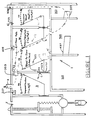
- a wound drainage apparatus 1 comprises a suction chamber 3 from which air can be evacuated by an external vacuum source such as a centrally located vacuum pump in a hospital, a suction port 4 for interconnecting chamber 3 with the external vacuum source, a suction regulator 5 for controlling the pressure in chamber 3, a suction measuring device 6, an instrument chamber 7, three collection chambers 303, 305, 307 for collecting fluids withdrawn from a patient, and an inlet port 308 for connecting chamber 303 to the patient.
- the collection chambers 303, 305, 307 are in fluid communication with each other as described hereinbelow and with the instrument chamber 7 through a vent 15.
- a conduit 32 having a one way valve 203 installed therein is provided in the wall which divides chambers 3 and 7.
- Air evacuated from a patient follows the path shown by the broken line a , passing through the one way valve 203 whenever the pressure in the collection chambers 303, 305, 307 and the instrument chamber 7 exceeds that in the suction chamber 3.
- the valve 203 is configured to close when the pressure in the suction chamber 3 exceeds that in chambers 7, 303, 305, 307.
- the patient air flow is usually the result of air flowing through a hole in the patient's lung into chambers 7, 303, 305, 307.
- the rate of air flow depends upon the pressure differential between chambers 3 and 7.
- This principle enables the provision of an air flow gauge 120, which includes a diaphragm 121 mounted in an opening in the wall between chambers 3 and 7.
- Diaphragm 121 is adapted to flex according to the extent of the pressure differential between the suction pressure in chamber 3 and the higher pressure in chamber 7.
- a rod 123 is attached to the diaphragm 121 and is movable therewith.
- a dial 125 is attached to the end of rod 123 by means of a swivel joint 127, and is rotatable about a pivot 129 in response to movement of diaphragm 121.
- a scale 131 is disposed adjacent the free end of dial 125 and is calibrated to indicate the air flow rate in litres per minute according to the position of dial 125.
- a patient negativity measuring device 151 is provided for this purpose, together with a device for storing the maximum value of patient negativity recorded over a period of time.
- the devices 151 and 152 are described with reference to Figure 4.
- the maximum value storage device 152 is contained within an atmospheric pressure chamber 153 which communicates with the ambient air through a port 155.
- the chambers 7 and 153 are divided by a wall 157 having an opening which is sealed by a diaphragm 159.
- a rod 161 is attached to the diaphragm 159 and has components 162 and 163 extending in opposite directions therefrom.
- Diaphragm 159 is flexible and moves between the unflexed position shown in solid lines and the flexed position shown in broken lines.
- Rod portion 162 is attached to a dial 165 by means of a swivel joint 167, and rod portion 163 terminates in an upstanding flange 169.
- Dial 165 rotates clockwise about a pivot 171 in response to the flexing of diaphragm 159, and a scale 173 at the free end of dial 165 indicates the instantaneous patient negativity in appropriate units such as -cm. of water.
- a dial 175 is pivotally mounted on a pivot mechanism 177 which retains the dial in its position of maximum (clockwise) rotation.
- Mechanism 177 can for example be a ratchet device.
- Flange 169 engages the lower end of dial 175 and rotates the dial in the clockwise direction when diaphragm 159 flexes according to the amount by which the atmospheric pressure in chamber 153 exceeds the patient pressure in chamber 7.
- a knob 179 is provided for releasing dial 177 to allow its resetting to 0.
- a scale 181 preferably calibrated in the manner of scale 173 cooperates with dial 175 to indicate the maximum patient negativity during any period of time prior to the release of dial 175 by knob 179.
- Suction regulator 5 includes a wall 41; a horizontal partition 43 dividing regulator 5 into an upper chamber 45 and a lower chamber 47; an opening 49 in partition 43 in which is seated a collar 51, the collar being a section of a sphere and having a diameter which increases from top to bottom; a light ball 53 whose diameter is slightly more than the diameter of the sphere of which collar 51 is a section so that the ball can fit and be seated in the collar but not pass upwardly through it; a cantilever support arm 55 having a threaded bore through which extends a threaded bolt 57 with an adjustment knob 58 (which could have detents to avoid accidental changes) and disposed on a support shelf 59; a vertical guide rod 60 mounted between shelf 59 and the top wall of the unit for extending through a smooth bore in arm 55 to guide
- Collar 51 preferably includes a set of notches 72 for enhancing the stabilizing effect of collar 51 on ball 53 as air flows between the collar and the ball.
- a piston chamber 74 is defined between the head of piston 67 and the closed bore of cylinder 69. Atmospheric air flow at pressure P A enters chamber 45 through an entrance port 75.
- Lower chamber 47 includes an entrance port 77 from suction chamber 3, and is connected to the hospital suction source 79 at pressure P S . Port 79 could be located in some other wall defining suction chamber 3. The path of flow is shown by the dotted arrows "a".
- the gauge pressure in suction chamber 3 is measured by negative pressure gauge 6 which is shown in detail in Figure 3.
- Gauge 6 includes a diaphragm 81 which covers an opening 83 in wall 41 between the upper chamber (which is at atmospheric pressure) of suction regulator 5 and gauge 6 (which is located in suction chamber 3), and a push rod 85 attached at one end to diaphragm 81 and at its other end to a dial 87.
- Push rod 85 should be light in weight to avoid drooping of the diaphragm.
- Dial 87 is mounted on a pivot 89 and has a free end which is movable across a negative pressure scale 91 shown calibrated in cm. of water.
- Diaphragm 81 flexes as shown in dotted lines according to the pressure differential between the pressure in chamber 3 and atmospheric pressure P A in chamber 45 (i.e. gauge pressure), and such flexure is reflected in the linear movement of push rod 85.
- Push rod 85 in turn pivots dial 87 about pivot 89 to reflect the negative pressure on scale 91.
- the short end of the dial lever arm 87 which is shown below pivot 89 is doubled back to extend in the same direction from pivot 89 as the long part of dial 87, the direction of movement of the dial and its corresponding scale can be reversed.
- the direct coupling of the push rod to the dial for effecting dial rotation could be replaced with magnetic drag between the end of the dial and the diaphragm push rod.
- the push rod and dial could be connected through a gear train with the gear ratio set to any value to accomodate different deflection or diaphragm sensitivities expected under different parameters.
- suction regulator 5 The operation of suction regulator 5 will now be explained.
- the attendant will have selected some desired negative pressure in chamber 3.
- Knob 58 is turned to raise or lower cantilever arm 55 to achieve a desired elongation of spring 61 according to the negative pressure sought.
- the pressure in upper chamber 45 will exceed the pressure in chamber 47, and the resultant force F A from atmospheric pressure P A applied over the exposed surface area A A of ball 53 in chamber 45 exceeds the resultant force F S from the negative or suction pressure P S applied over the area A S of ball 53 in chamber 47.
- Suction regulator 5 as described thus far would provide for the rapid modulation of ball 53 as the pressure differential across it varies.
- dashpot 65 is provided.
- resultant force F R becomes downward, ball 53 does not immediately pop open. Rather, the downward movement of ball 53 urges piston 67 downwardly to compress the air in piston chamber 74.
- the downward movement of piston 67 is slowed down, since air in chamber 74 compresses slowly and air can only leak out between piston 67 and the inner wall of cylinder 69 slowly.
- the resultant force F R is upward, the movement of ball 53 from its open to its closed position is also slowed down.
- the air leakage about cylinder 69 reduces the effect of friction between the cylinder wall and piston 67.
- Wound drainage apparatus of Figure 1 includes a negativity release valve 205.
- This valve vents atmospheric air into chamber 7 when the patient negativity exceeds the closing bias on valve 205.
- Valve 205 can be adjusted by means of spring tension in the manner of regulator 5, a weighted ball if a fixed value is acceptable, or a button actuated release.
- a positive pressure vent 207 is provided to open suction chamber 3 to the atmosphere to avoid a build-up of positive pressure air (i.e. above atmospheric pressure air) in chamber 3 should there be a failure of the suction source.
- the drainage systems, suction regulators and other devices provided in the apparatus described offer numerous advantages over the prior art.
- the apparatus in its various forms is dry, and thus avoids the various shortcomings of systems relying on water for regulating and measuring the various pressure values.
- the apparatus and its components are of very simple construction, contributing to the ease of manufacture, use and general economy thereof.
- the apparatus and its components are compact and light, rendering it easy to store and use. Yet, despite its simplicity, it is highly effective in use.
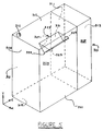
- Device 301 is composed of vertical side walls 309, 311 and 313, which with a bottom wall 315, a top wall 317, rear wall 319 and a front wall 321 define adjoining prismatic fluid collection chambers 303 and 305.
- a fluid entrance port 310 is located in top wall 317.
- a triangular conduit 323 extends perpendicularly from a triangular opening 325 in side wall 311.
- Conduit 323 is composed of side walls 327 and 329, and a top wall 331. The lowermost entrance to conduit 323 is a point 333 at the juncture of walls 327 and 329 and an imaginary plane across that entrance.
- Point 333 is located midway both between rear wall 319 and front wall 321 and a distance l/2 from side wall 309.
- the measurement l/2 is optional but can be chosen to move point 333 as close as possible to side wall 309 without interfering with fluid flow, blood clots or the like. Since the diameter of the entrance tubes is normally in the range of 3/8" (9.53 mm), the minimum length of l/2 will be comparable with that dimension as well.
- the positioning of the lowest entrance point of the conduit from chamber 303 to chamber 305 effectively enables the maximum amount of rotation of chamber 303 in either the x-axis or the z-axis for any given amount of fluid in chamber 303 before there can be any spill-over of fluid from chamber 303 to chamber 305.
- the minimum distance of point 333 below upper wall 317 will depend on, and can be calculated from, the other dimensions of chamber 303.
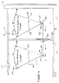
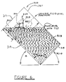
- FIG. 6 The manner in which the construction of the device 301 reduces spillage of fluid from chamber 303 is shown in Figures 6 and 7.
- chamber 303 is shown tilted such that rear wall 319 is at an angle ⁇ from horizontal, angle 90- ⁇ being the maximum amount of tilt permissible in that axis for preventing spilling of the fluid in chamber 303 under all conditions of fluid level.
- Walls 327 and 329 intersect at an angle 2 ⁇ .
- Collection chamber 303 can be rotated by an angle 90°- ⁇ about an axis perpendicular to wall 309 before any fluid can enter conduit 323 and flow out of chamber 303. Were point 333 any closer to either of walls 319 or 321, spill-over would occur sooner for rotation in one direction or the other.
- chamber 303 can be rotated around the x-axis well in excess of the indicated tilt angle ⁇ before any fluids enter conduit 323 leading to the adjacent collection chamber 305.
- the amount chamber 303 can be rotated clockwise about an axis perpendicular to wall 321 (x-axis) is increased, in fact, if the calculation for d (as derived above) is satisfied, ⁇ can be increased to 90° with no danger of spillover.
- ⁇ can be increased to 90° with no danger of spillover.
- fluid would begin entering the conduit sooner but would not spill over into chamber 305 until the fluid level exceeds point 335.
- conduit length could be shortened to lie midway between walls 309 and 311 and a geometric/trigonometric relationship can be formulated for rotation about the x-axis similar to that for rotation about the z-axis.
- point 333 is situated at the horizontal centre of gravity of chamber 303.
- Figures 5 to 7 show the collection chamber arrangement to include two chambers. Any number of chambers can be arranged adjacent each other with spill-over reducing conduits 323 provided therein. In Figure 1, three such chambers 303, 305, and 307 are provided, with chambers 303 and 305 having spill-over reduction conduits 323 and 337, respectively, incorporated therein.
Landscapes
- Health & Medical Sciences (AREA)
- Heart & Thoracic Surgery (AREA)
- Engineering & Computer Science (AREA)
- Public Health (AREA)
- Anesthesiology (AREA)
- Biomedical Technology (AREA)
- Hematology (AREA)
- Life Sciences & Earth Sciences (AREA)
- Animal Behavior & Ethology (AREA)
- General Health & Medical Sciences (AREA)
- Vascular Medicine (AREA)
- Veterinary Medicine (AREA)
- General Engineering & Computer Science (AREA)
- Mechanical Engineering (AREA)
- External Artificial Organs (AREA)
- Catching Or Destruction (AREA)
- Fluid-Pressure Circuits (AREA)
- Earth Drilling (AREA)
- Apparatus For Radiation Diagnosis (AREA)
- Electrical Discharge Machining, Electrochemical Machining, And Combined Machining (AREA)
Claims (3)
- Vorrichtung (1) zur Drainage von Strömungsmitteln oder Flüssigkeiten aus einem Teil eines Körpers eines Patienten, wobei die Vorrichtung einen Behälter (303, 305, 307) zur Aufnahme der Körperflüssigkeiten aufweist, wobei der Behälter (303, 305, 307) folgendes aufweist: eine erste Sammelkammer (303), die einen Einlaßanschluß (310) um Hereinlassen der Körperflüssigkeiten in die Kammer (303) besitzt und eine zweite Sammelkammer (305) zur Aufnahme der überströmenden Körperflüssigkeiten von der ersten Sammelkammer (303), wenn die letztere voll ist, wobei die ersten und zweiten Sammelkammern (303, 305) durch eine Wand (311) aufgeteilt sind,
gekennzeichnet durch Vorsehen von Mitteln zum Einschränken des Überlaufens oder Verschüttens der Körperflüssigkeiten von der ersten Sammelkammer (303), wenn diese nicht voll ist, zu der zweiten Sammelkammer (305), was sich durch ein Kippen oder eine andere Bewegung der Vorrichtung ergibt, wobei die Überlaufeinschränkmittel eine Leitung (323) für die Körperflüssigkeiten aufweisen, wobei sich die Leitung von einem Anschluß (325) in der Wand (311) zu einem Leitungseingang (333) inerhalb der ersten Sammelkammer (303) erstreckt, wobei die Leitung (323) zur Horizontalen geneigt ist, wenn die Vorrichtung in ihrer normalen Verwendungslage ist, wobei der Leitungseingang (333) niedriger liegt als der Anschluß (325). - Vorrichtung nach Anspruch 1, wobei die erste Sammelkammer (303) einen prismatischen Aufbau besitzt, der definiert wird durch gegenüberliegende parallele obere (317) und untere (315) Wände, gegenüberliegende parallele Vorder- (321) und Rück- (319) Wände, die sich zwischen den Ober- (317) und Unter- (315) Wänden erstrecken und gegenüberliegende parallele Seitenwände (309, 311), die die Vorder- (321) und Rück- (319) Wände und die oberen (317) und unteren (315) Wände verbinden und wobei der unterste Punkt des Leitungseingangs (333) mit einem Abstand (d) von der oberen Wand (317) angeordnet ist, um das Sammeln der maximalen Strömungsmittel oder Flüssigkeitsmenge zu erlauben, ohne ein Überlaufen durch den Leitungseingang (333), wenn die erste Sammelkammer (303) um eine Achse senkrecht zu den Seitenwänden (309, 311) um einen Maximalwinkel gedreht wird, bevor ein Überlaufen auftritt, und zwar gemäß der folgenden Berechnung:
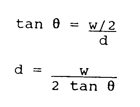 90-Θ = der maximale Drehwinkel vor dem Überlaufen um eine Achse senkrecht zu den Seitenwänden (309, 311);w = der Abstand zwischen den Seitenwänden (319, 321);d = der Abstand von der oberen Wand (317) zu dem untersten Punkt des Leitungseinlasses (333) zum Ermöglichen der maximalen Drehgröße ohne Überlaufen durch den Leitungseinlaß (333).
- Vorrichtung nach Anspruch 1, wobei die Strömungsmittelsammelkammer (303) definiert wird durch Oberflächen, die um eine erste Ebene, die eine zentrale Vertikalachse aufweist, symmetrisch sind und wobei der unterste Punkt des Leitungseinlasses (333) mit einem Abstand (d) von dem Schnittpunkt der obersten der Oberflächen und der vertikalen Achse liegt, um das Sammeln der maximalen Strömungsmittelmenge zu ermöglichen, ohne Überlaufen durch den Leitungseinlaß (333), wenn die Kammer (303) um eine erste Achse senkrecht zu der Vertikalachse um einen Maximalwinkel gedreht wird, bevor ein Überlaufen auftritt, und zwar gemäß der folgenden Berechnung:
 90-Θ = der maximale Drehwinkel vor dem Überlaufen um eine erste Achse senkrecht zu der Vertikalachse;w = der Abstand zwischen der nächsten Wand, die die Kammer (303) definiert, und zwar entlang einer Linie senkrecht zu der Vertikalachse an der Stelle des untersten Punktes des Leitungseinlasses (333);d = der Abstand entlang der Vertikalachse von dem Schnittpunkt der obersten Oberfläche, die die Kammer (303) definiert und der Vertikalachse zu dem untersten Punkt des Leitungseinlasses (333).
Applications Claiming Priority (3)
| Application Number | Priority Date | Filing Date | Title |
|---|---|---|---|
| US642563 | 1984-08-20 | ||
| US06/642,563 US4698060A (en) | 1984-08-20 | 1984-08-20 | Pressure regulation system |
| EP19850904212 EP0189477B1 (de) | 1984-08-20 | 1985-08-15 | Druckreglersystem |
Related Parent Applications (2)
| Application Number | Title | Priority Date | Filing Date |
|---|---|---|---|
| EP19850904212 Division EP0189477B1 (de) | 1984-08-20 | 1985-08-15 | Druckreglersystem |
| EP85904212.9 Division | 1986-03-05 |
Publications (3)
| Publication Number | Publication Date |
|---|---|
| EP0479770A2 EP0479770A2 (de) | 1992-04-08 |
| EP0479770A3 EP0479770A3 (de) | 1992-04-22 |
| EP0479770B1 true EP0479770B1 (de) | 1995-06-14 |
Family
ID=24577118
Family Applications (2)
| Application Number | Title | Priority Date | Filing Date |
|---|---|---|---|
| EP19850904212 Expired - Lifetime EP0189477B1 (de) | 1984-08-20 | 1985-08-15 | Druckreglersystem |
| EP19920100413 Expired - Lifetime EP0479770B1 (de) | 1984-08-20 | 1985-08-15 | System zur Wunddrainage mit Schutz gegen das Ausschütten |
Family Applications Before (1)
| Application Number | Title | Priority Date | Filing Date |
|---|---|---|---|
| EP19850904212 Expired - Lifetime EP0189477B1 (de) | 1984-08-20 | 1985-08-15 | Druckreglersystem |
Country Status (7)
| Country | Link |
|---|---|
| US (1) | US4698060A (de) |
| EP (2) | EP0189477B1 (de) |
| JP (1) | JPH0673545B2 (de) |
| AT (2) | ATE123654T1 (de) |
| CA (1) | CA1242123A (de) |
| DE (2) | DE3588029T2 (de) |
| WO (1) | WO1986001114A1 (de) |
Families Citing this family (33)
| Publication number | Priority date | Publication date | Assignee | Title |
|---|---|---|---|---|
| US5300050A (en) * | 1986-10-07 | 1994-04-05 | Deknatel Technology Corporation | Drainage device |
| US4784642A (en) * | 1986-10-07 | 1988-11-15 | Pfizer Hospital Products Group, Inc. | Meterless drainage device with suction control |
| US5026358A (en) * | 1986-10-07 | 1991-06-25 | Pfizer Products Hospital Group Inc. | Drainage device |
| US4756501A (en) * | 1986-10-07 | 1988-07-12 | Pfizer Hospital Products Group, Inc. | Hanger for drainage device |
| US5141504A (en) * | 1987-03-02 | 1992-08-25 | Atrium Medical Corporation | Fluid recovery system with stopcock suction control |
| US5807359A (en) | 1993-06-08 | 1998-09-15 | Bemis Manufacturing Company | Medical suction system |
| US5380280A (en) * | 1993-11-12 | 1995-01-10 | Peterson; Erik W. | Aspiration system having pressure-controlled and flow-controlled modes |
| US6358232B1 (en) | 1994-12-29 | 2002-03-19 | Bemis Manufacturing Company | Method and apparatus for removing and disposing of body fluids |
| US6244311B1 (en) | 1994-12-29 | 2001-06-12 | Bemis Manufacturing Company | Method and apparatus for removing and disposing of body fluids |
| US5885261A (en) * | 1996-04-25 | 1999-03-23 | C. R. Bard, Inc. | Autotransfusion system and method |
| US5989234A (en) * | 1997-01-14 | 1999-11-23 | Deknatel Technology Corporation | Device and system for draining a body cavity and methods related thereto |
| US6447491B1 (en) * | 1999-06-18 | 2002-09-10 | Genzyme Corporation | Rolling seal suction pressure regulator, apparatus and system for draining a body cavity and methods related thereto |
| WO2001072350A1 (en) | 2000-03-28 | 2001-10-04 | Bemis Manufacturing Company | Medical suction apparatus and methods for draining same |
| US7674248B2 (en) | 2000-03-28 | 2010-03-09 | Bemis Manufacturing Company | Medical suction apparatus and methods for draining same |
| US7585292B2 (en) | 2000-03-28 | 2009-09-08 | Bemis Manufacturing Company | Medical suction apparatus and draining of same |
| EP1184042B1 (de) * | 2000-08-28 | 2006-07-26 | Medela AG | Absaugpumpe |
| US6672477B2 (en) | 2001-01-12 | 2004-01-06 | Bemis Manufacturing Company | Method and apparatus for disposing of bodily fluids from a container |
| US6554022B2 (en) | 2001-05-30 | 2003-04-29 | Illinois Tool Works Inc. | Regulator with improved seat |
| GB0113750D0 (en) * | 2001-06-06 | 2001-07-25 | Rocket Medical Plc | Autologous blood transfusion apparatus |
| US6955664B2 (en) * | 2001-07-17 | 2005-10-18 | D'antonio Consultants International, Inc. | Suction regulator and fluid drainage system |
| US7340966B2 (en) * | 2005-08-24 | 2008-03-11 | Ric Investments, Llc | Sensor with water ingress protection |
| CN101511277B (zh) * | 2006-09-19 | 2013-05-22 | 凯希特许有限公司 | 具有阻塞清除和双区压力保护能力的减压治疗系统 |
| US8366690B2 (en) | 2006-09-19 | 2013-02-05 | Kci Licensing, Inc. | System and method for determining a fill status of a canister of fluid in a reduced pressure treatment system |
| RU2428208C2 (ru) | 2007-02-09 | 2011-09-10 | КейСиАй Лайсензинг Инк. | Система и способ управления пониженным давлением на участке ткани |
| AU2008219034B2 (en) | 2007-02-20 | 2012-01-19 | Solventum Intellectual Properties Company | System and method for distinguishing leaks from a disengaged canister condition in a reduced pressure treatment system |
| US8267909B2 (en) * | 2008-05-01 | 2012-09-18 | Devilbiss Healthcare, Llc | Canister having fluid flow control |
| US8256453B2 (en) * | 2008-05-01 | 2012-09-04 | Devilbiss Healthcare, Llc | Vacuum regulator having selectable adjustment ranges |
| EP2992912B1 (de) | 2008-08-08 | 2017-11-22 | KCI Licensing, Inc. | Behandlungssysteme mit reduziertem druck mit behältersteuerung |
| US7798009B2 (en) * | 2009-02-17 | 2010-09-21 | Pacific Hospital Supply Co., Ltd. | Negative pressure gauge with a switch |
| CA2756998A1 (en) | 2009-04-03 | 2010-10-07 | Ctb, Inc. | Pressure regulator for watering system |
| WO2018070454A1 (ja) * | 2016-10-14 | 2018-04-19 | 株式会社村田製作所 | 吸引排出ユニット及び吸引排出装置 |
| US10871260B2 (en) | 2019-02-20 | 2020-12-22 | Goodrich Corporation | Monolithic pressure regulator |
| CN119971162A (zh) * | 2025-02-08 | 2025-05-13 | 西安市第九医院(西安市铁路中心医院) | 一种创面的封闭式负压引流装置 |
Family Cites Families (18)
| Publication number | Priority date | Publication date | Assignee | Title |
|---|---|---|---|---|
| US869323A (en) * | 1906-11-07 | 1907-10-29 | Richard Peter Nolan | Automatic warning-signal for air-brake systems. |
| US1074306A (en) * | 1911-07-11 | 1913-09-30 | Franz Emil Wolf | Differential manometer. |
| US2286841A (en) * | 1939-07-20 | 1942-06-16 | Linde Air Prod Co | Valve |
| US2280992A (en) * | 1940-01-08 | 1942-04-28 | Russell M Wright | Apparatus for treating nasal organs |
| US2714392A (en) * | 1952-04-08 | 1955-08-02 | Mercier Jean | Valves |
| US2764894A (en) * | 1953-01-26 | 1956-10-02 | Faxen Per Torsten | Apparatus for translating linear motion into rotary motion |
| US3545440A (en) * | 1968-07-09 | 1970-12-08 | Deknatel Inc | Single chamber underwater drainage apparatus |
| US3699815A (en) * | 1971-12-13 | 1972-10-24 | Medical Dev Corp | Improvements in body fluid collection bottle |
| US3763884A (en) * | 1972-02-14 | 1973-10-09 | R Grassi | Constant volume flow device |
| US3863671A (en) * | 1973-03-12 | 1975-02-04 | Zero Manufacturing Co | Vacuum regulator control |
| SE381986B (sv) * | 1974-01-14 | 1976-01-12 | Meteve Ab | Blodtomningsmanschett for blodtomning av extremitetet fore ett operativt ingrepp |
| US4036231A (en) * | 1975-11-20 | 1977-07-19 | Sherwood Medical Industries Inc. | Thoracic drainage unit with defoaming means |
| DE2757352B2 (de) * | 1977-12-22 | 1981-06-19 | Carl Heinz Dipl.-Ing. 4050 Mönchengladbach Häfele | Selbsttätig arbeitendes Rückschlagventil |
| US4296748A (en) * | 1979-06-27 | 1981-10-27 | Bioresearch Inc. | Underwater drainage apparatus with separable suction control chamber |
| CA1178866A (en) * | 1980-06-06 | 1984-12-04 | Donald P. Elliott | Chest drainage apparatus |
| JPS58175562A (ja) * | 1982-04-08 | 1983-10-14 | 株式会社ゼニ− | 乾式排液抽出装置 |
| US4544370A (en) * | 1982-05-24 | 1985-10-01 | C. R. Bard, Inc. | Air leak detection system for chest fluid collection bottles and blow-out prevention baffle |
| US4468226A (en) * | 1982-06-08 | 1984-08-28 | Bioresearch Inc. | Surgical drainage apparatus with incremental suction control and indication |
-
1984
- 1984-08-20 US US06/642,563 patent/US4698060A/en not_active Expired - Lifetime
-
1985
- 1985-08-15 AT AT92100413T patent/ATE123654T1/de not_active IP Right Cessation
- 1985-08-15 AT AT85904212T patent/ATE79280T1/de not_active IP Right Cessation
- 1985-08-15 EP EP19850904212 patent/EP0189477B1/de not_active Expired - Lifetime
- 1985-08-15 DE DE3588029T patent/DE3588029T2/de not_active Expired - Lifetime
- 1985-08-15 JP JP50368385A patent/JPH0673545B2/ja not_active Expired - Lifetime
- 1985-08-15 EP EP19920100413 patent/EP0479770B1/de not_active Expired - Lifetime
- 1985-08-15 DE DE8585904212T patent/DE3586492T2/de not_active Expired - Lifetime
- 1985-08-15 WO PCT/US1985/001558 patent/WO1986001114A1/en not_active Ceased
- 1985-08-20 CA CA000489018A patent/CA1242123A/en not_active Expired
Also Published As
| Publication number | Publication date |
|---|---|
| EP0479770A3 (de) | 1992-04-22 |
| EP0479770A2 (de) | 1992-04-08 |
| DE3586492D1 (de) | 1992-09-17 |
| US4698060A (en) | 1987-10-06 |
| WO1986001114A1 (en) | 1986-02-27 |
| EP0189477A1 (de) | 1986-08-06 |
| DE3586492T2 (de) | 1993-04-08 |
| DE3588029D1 (de) | 1995-07-20 |
| DE3588029T2 (de) | 1996-02-08 |
| EP0189477B1 (de) | 1992-08-12 |
| JPS61503009A (ja) | 1986-12-25 |
| CA1242123A (en) | 1988-09-20 |
| ATE123654T1 (de) | 1995-06-15 |
| JPH0673545B2 (ja) | 1994-09-21 |
| ATE79280T1 (de) | 1992-08-15 |
| EP0189477A4 (de) | 1988-06-27 |
Similar Documents
| Publication | Publication Date | Title |
|---|---|---|
| EP0479770A2 (de) | System zur Wunddrainage mit Schutz gegen das Ausschütten | |
| US4889531A (en) | Dry bottle drainage system | |
| US4715855A (en) | Dry bottle drainage system | |
| US4902284A (en) | Dry bottle drainage system | |
| EP0065386B1 (de) | Chirurgischer Drainageapparat mit Regelung und Anzeige der Saugwirkung | |
| US4468226A (en) | Surgical drainage apparatus with incremental suction control and indication | |
| US6955664B2 (en) | Suction regulator and fluid drainage system | |
| EP0200005B1 (de) | Elektronische Vorrichtung zur Drainage | |
| EP0138989B1 (de) | Drainagevorrichtung mit absaugung oder freiem abfluss | |
| US5300050A (en) | Drainage device | |
| US5450750A (en) | Body volume measurement chamber | |
| US5026358A (en) | Drainage device | |
| US4784642A (en) | Meterless drainage device with suction control | |
| GB2200194A (en) | Suction regulator | |
| JPS59502012A (ja) | 尿計量装置 | |
| US4541276A (en) | Contents gage | |
| JPH0342926Y2 (de) | ||
| IE58296B1 (en) | Electronic drainage system | |
| AU2003204071A1 (en) | Suction regulator and fluid drainage system | |
| AU2262083A (en) | Device for measuring urine |
Legal Events
| Date | Code | Title | Description |
|---|---|---|---|
| PUAI | Public reference made under article 153(3) epc to a published international application that has entered the european phase |
Free format text: ORIGINAL CODE: 0009012 |
|
| PUAL | Search report despatched |
Free format text: ORIGINAL CODE: 0009013 |
|
| 17P | Request for examination filed |
Effective date: 19920113 |
|
| AC | Divisional application: reference to earlier application |
Ref document number: 189477 Country of ref document: EP |
|
| AK | Designated contracting states |
Kind code of ref document: A2 Designated state(s): AT BE CH DE FR GB IT LI LU NL SE |
|
| AK | Designated contracting states |
Kind code of ref document: A3 Designated state(s): AT BE CH DE FR GB IT LI LU NL SE |
|
| 17Q | First examination report despatched |
Effective date: 19931124 |
|
| GRAA | (expected) grant |
Free format text: ORIGINAL CODE: 0009210 |
|
| AC | Divisional application: reference to earlier application |
Ref document number: 189477 Country of ref document: EP |
|
| AK | Designated contracting states |
Kind code of ref document: B1 Designated state(s): AT BE CH DE FR GB IT LI LU NL SE |
|
| PG25 | Lapsed in a contracting state [announced via postgrant information from national office to epo] |
Ref country code: IT Free format text: LAPSE BECAUSE OF FAILURE TO SUBMIT A TRANSLATION OF THE DESCRIPTION OR TO PAY THE FEE WITHIN THE PRESCRIBED TIME-LIMIT;WARNING: LAPSES OF ITALIAN PATENTS WITH EFFECTIVE DATE BEFORE 2007 MAY HAVE OCCURRED AT ANY TIME BEFORE 2007. THE CORRECT EFFECTIVE DATE MAY BE DIFFERENT FROM THE ONE RECORDED. Effective date: 19950614 Ref country code: NL Free format text: LAPSE BECAUSE OF NON-PAYMENT OF DUE FEES Effective date: 19950614 Ref country code: AT Effective date: 19950614 Ref country code: BE Effective date: 19950614 Ref country code: LI Effective date: 19950614 Ref country code: CH Effective date: 19950614 |
|
| REF | Corresponds to: |
Ref document number: 123654 Country of ref document: AT Date of ref document: 19950615 Kind code of ref document: T |
|
| REF | Corresponds to: |
Ref document number: 3588029 Country of ref document: DE Date of ref document: 19950720 |
|
| ET | Fr: translation filed | ||
| PG25 | Lapsed in a contracting state [announced via postgrant information from national office to epo] |
Ref country code: LU Free format text: LAPSE BECAUSE OF NON-PAYMENT OF DUE FEES Effective date: 19950831 |
|
| PG25 | Lapsed in a contracting state [announced via postgrant information from national office to epo] |
Ref country code: SE Effective date: 19950914 |
|
| REG | Reference to a national code |
Ref country code: CH Ref legal event code: PL |
|
| NLV1 | Nl: lapsed or annulled due to failure to fulfill the requirements of art. 29p and 29m of the patents act | ||
| PLBE | No opposition filed within time limit |
Free format text: ORIGINAL CODE: 0009261 |
|
| STAA | Information on the status of an ep patent application or granted ep patent |
Free format text: STATUS: NO OPPOSITION FILED WITHIN TIME LIMIT |
|
| 26N | No opposition filed | ||
| REG | Reference to a national code |
Ref country code: GB Ref legal event code: IF02 |
|
| PGFP | Annual fee paid to national office [announced via postgrant information from national office to epo] |
Ref country code: GB Payment date: 20040811 Year of fee payment: 20 |
|
| PGFP | Annual fee paid to national office [announced via postgrant information from national office to epo] |
Ref country code: FR Payment date: 20040819 Year of fee payment: 20 |
|
| PGFP | Annual fee paid to national office [announced via postgrant information from national office to epo] |
Ref country code: DE Payment date: 20040930 Year of fee payment: 20 |
|
| PG25 | Lapsed in a contracting state [announced via postgrant information from national office to epo] |
Ref country code: GB Free format text: LAPSE BECAUSE OF EXPIRATION OF PROTECTION Effective date: 20050814 |
|
| REG | Reference to a national code |
Ref country code: GB Ref legal event code: PE20 |