EP0479936B1 - Förderband - Google Patents
Förderband Download PDFInfo
- Publication number
- EP0479936B1 EP0479936B1 EP90917829A EP90917829A EP0479936B1 EP 0479936 B1 EP0479936 B1 EP 0479936B1 EP 90917829 A EP90917829 A EP 90917829A EP 90917829 A EP90917829 A EP 90917829A EP 0479936 B1 EP0479936 B1 EP 0479936B1
- Authority
- EP
- European Patent Office
- Prior art keywords
- rods
- conveyor belt
- link
- wire
- belt
- Prior art date
- Legal status (The legal status is an assumption and is not a legal conclusion. Google has not performed a legal analysis and makes no representation as to the accuracy of the status listed.)
- Expired - Lifetime
Links
Images


Classifications
-
- B—PERFORMING OPERATIONS; TRANSPORTING
- B65—CONVEYING; PACKING; STORING; HANDLING THIN OR FILAMENTARY MATERIAL
- B65G—TRANSPORT OR STORAGE DEVICES, e.g. CONVEYORS FOR LOADING OR TIPPING, SHOP CONVEYOR SYSTEMS OR PNEUMATIC TUBE CONVEYORS
- B65G21/00—Supporting or protective framework or housings for endless load-carriers or traction elements of belt or chain conveyors
- B65G21/16—Supporting or protective framework or housings for endless load-carriers or traction elements of belt or chain conveyors for conveyors having endless load-carriers movable in curved paths
- B65G21/18—Supporting or protective framework or housings for endless load-carriers or traction elements of belt or chain conveyors for conveyors having endless load-carriers movable in curved paths in three-dimensionally curved paths
-
- B—PERFORMING OPERATIONS; TRANSPORTING
- B65—CONVEYING; PACKING; STORING; HANDLING THIN OR FILAMENTARY MATERIAL
- B65G—TRANSPORT OR STORAGE DEVICES, e.g. CONVEYORS FOR LOADING OR TIPPING, SHOP CONVEYOR SYSTEMS OR PNEUMATIC TUBE CONVEYORS
- B65G17/00—Conveyors having an endless traction element, e.g. a chain, transmitting movement to a continuous or substantially-continuous load-carrying surface or to a series of individual load-carriers; Endless-chain conveyors in which the chains form the load-carrying surface
- B65G17/06—Conveyors having an endless traction element, e.g. a chain, transmitting movement to a continuous or substantially-continuous load-carrying surface or to a series of individual load-carriers; Endless-chain conveyors in which the chains form the load-carrying surface having a load-carrying surface formed by a series of interconnected, e.g. longitudinal, links, plates, or platforms
- B65G17/063—Conveyors having an endless traction element, e.g. a chain, transmitting movement to a continuous or substantially-continuous load-carrying surface or to a series of individual load-carriers; Endless-chain conveyors in which the chains form the load-carrying surface having a load-carrying surface formed by a series of interconnected, e.g. longitudinal, links, plates, or platforms the load carrying surface being formed by profiles, rods, bars, rollers or the like attached to more than one traction element
- B65G17/064—Conveyors having an endless traction element, e.g. a chain, transmitting movement to a continuous or substantially-continuous load-carrying surface or to a series of individual load-carriers; Endless-chain conveyors in which the chains form the load-carrying surface having a load-carrying surface formed by a series of interconnected, e.g. longitudinal, links, plates, or platforms the load carrying surface being formed by profiles, rods, bars, rollers or the like attached to more than one traction element the profiles, rods, bars, rollers or the like being interconnected by a mesh or grid-like structure
-
- B—PERFORMING OPERATIONS; TRANSPORTING
- B65—CONVEYING; PACKING; STORING; HANDLING THIN OR FILAMENTARY MATERIAL
- B65G—TRANSPORT OR STORAGE DEVICES, e.g. CONVEYORS FOR LOADING OR TIPPING, SHOP CONVEYOR SYSTEMS OR PNEUMATIC TUBE CONVEYORS
- B65G2201/00—Indexing codes relating to handling devices, e.g. conveyors, characterised by the type of product or load being conveyed or handled
- B65G2201/02—Articles
-
- B—PERFORMING OPERATIONS; TRANSPORTING
- B65—CONVEYING; PACKING; STORING; HANDLING THIN OR FILAMENTARY MATERIAL
- B65G—TRANSPORT OR STORAGE DEVICES, e.g. CONVEYORS FOR LOADING OR TIPPING, SHOP CONVEYOR SYSTEMS OR PNEUMATIC TUBE CONVEYORS
- B65G2207/00—Indexing codes relating to constructional details, configuration and additional features of a handling device, e.g. Conveyors
- B65G2207/24—Helical or spiral conveying path
Definitions
- the present invention relates to an endless conveyor belt for an air treatment plant in which the conveyor belt, over part of its length, travels in a helical path and comprises a bottom consisting of transverse rods and a wire netting, and side plates fixedly connected in pairs with two rods so as to form, together with these rods, a link which is movable relative to adjoining links about two axes perpendicular to the longitudinal direction of the belt and situated one in the plane of the bottom and the other perpendicular thereto.
- Conveyor belts of this type are disclosed by e.g. SE, C, 8206760-4, SE, C, 8506136-4 and DK-B-134 272.
- These conveyor belts are, furthermore, self-stacking, i.e. the side plates also serve as spacers, the upper edge portions of which are adapted to engage the lower edge portions of the overlying turn of the conveyor belt so as to support this turn.
- the wire netting forming part of the bottom consists of zig-zag wires each enclosing two adjacent rods, each of which is enclosed by two such wires.
- the zig-zag wires When the known belt travels around a curve about an axis which is perpendicular to both the longitudinal direction of the belt and the plane of the bottom, the zig-zag wires will be pushed into one another to an extent increasing progressively towards the inner side of the curve. This reduces the guiding effect of the rods on the zig-zag wires so that the zig-zag wires no longer form a completely flat supporting surface for the products carried on the bottom for air treatment, such as cooling, heating or drying.
- the object of the present invention is, therefore, to provide a conveyor belt of the type mentioned in the introduction to this specification, in which the wire netting consists of but one type of zig-zag wires which, furthermore, form a completely flat supporting surface also when travelling around a curve.
- the wire netting consists of zig-zag wires, each of which encloses not only the two rods of one link but also one adjacent rod of the adjoining link.
- every second rod in the conveyor belt is enclosed by two wires, while the remaining rods are enclosed by but one wire.
- the extension of the zig-zag wires in the longitudinal direction of the belt substantially corresponds to the relative displacement of two successive wires in the longitudinal direction of the belt.
- each wire may be fixed to one of the two rods of the associated link.
- each wire is fixed to the central one of the three rods enclosed by said wire.
- each wire may, between its ends and at at least one point, be fixed to one of the two rods of the associated link.
- the conveyor belt may have side plates overlapping each other. More precisely, each side plate may have a section which overlaps the corresponding side plate of an adjoining link and has an elongate hole through which passes one rod of the adjoining link.
- the invention can be applied to self-stacking as well as to non-self-stacking conveyor belts.
- the side plates of the links may serve as spacers, the upper edge portions of which are adapted to support the links of an overlying turn in the helical part of the conveyor belt path.
- the zig-zag wires in the conveyor belt according to the invention only serve to form a product-supporting surface and do not take up the tension in the belt caused by the pulling force applied to the moving belt. Instead, the pulling force is taken up via the side plates at at least one side of the belt.
- An endless conveyor belt 1 adapted for e.g. a conveyor of the type illustrated in Fig 1, is, as shown in the Figures, arranged to travel, over part of its length, in a helical path in a number of superimposed turns.
- the conveyor belt 1, which is partially shown in Figs 2 and 3, comprises a number of hingedly interconnected and relatively adjustable links which consist of a bottom 2 and side plates 3 provided at the sides of the bottom and forming the two sides of the conveyor belt 1.
- these side plates are also arranged to serve as spacers, the upper edge portions 4 of which engage the lower edge portions of the spacers of the overlying belt turn, to support this turn via its edge portions.
- the bottom 2 consists of transverse rods 5 which are fixedly connected in pairs with two side plates 3.
- the rods 5 are provided with a wire netting to be described later on and serving as a supporting surface for the products to be air-treated and allowing a relative displacement of the links in the longitudinal direction of the belt, as well as relative turning of the links about two axes perpendicular to the longitudinal direction of the belt and located one in the plane of the bottom 2 and the other perpendicular thereto.
- the side plates 3 are, over a part 6 of their length, fixedly connected to the longitudinal edges of the bottom 2. In the embodiment shown, this has been achieved by fixedly connecting the side plates with two of the rods 5 which are spaced apart in the longitudinal direction of the belt 1.
- the flanges 8 of successive side plates 3 form inner shoulders which engage the inside of the upper edge portion 4 of the side plates 3 of the underlying belt turn.
- a lower portion 9 of the part 6 is bent downwardly and outwardly, merging with a further outwardly bent portion 10 which extends substantially perpendicular to the side plates 3.
- the bent portions 9 of successive side plates 3 form outer shoulders which engage the outside of the upper edge portion 4 of a side plate 3 of the underlying belt turn.
- the upper edge portion 4 is positively guided in the lateral direction between opposing shoulders formed by the flanges 8 and the bent portions 9 alternating therewith in the longitudinal direction of the belt.
- the part 6 of each side plate 3 is, via a transition area 11, slightly offset laterally relative to the movable part 7, the part 6 overlapping the outer side of the part 7 of the adjacent side plate 3. Furthermore, the part 7 has an elongate hole 12 accommodating the rod 5 of an adjacent side plate 3 and facilitating adjustment of the links relative to one another in the longitudinal direction of the belt, e.g. when the belt is taken around a curve in the plane of the bottom 2.
- Fig 5 shows the conveyor belt in Fig 3 provided with a prior art wire netting which consists of two wire types 13, 14 which both are wound zig-zag about two adjacent rods 5.
- One wire type 13 encloses the two rods 5 of one and the same link and is, at its ends, fixedly connected with one or the other of the two rods 5. Thus, this type of wire is fixed relative to one link.
- the other wire type 14 encloses two rods 5 each belonging to one of two adjoining links. At one end, the wire type 14 is fixedly connected with one rod 5, while it is, at its other end, movable relative to both of the enclosed rods 5.
- this wire may thus, in the area nearest to the inner side of a curve, become inclined relative to the plane of the bottom 2 so that it does not give the desired flat product-supporting surface.
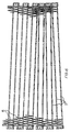
- Fig 6 shows the conveyor belt in Fig 3 provided with the wire netting according to the invention.
- This wire netting consists of identical zig-zag wires 15.
- each wire 15 encloses not only the two rods 5 of the associated link, but also an adjacent rod 5 in an adjoining link.
- the zig-zag wires 15 may also be defined as a flat spiral whose largest width roughly corresponds to twice the distance between the rods 5, and whose smallest width approximately corresponds to the diameter of the rods 5.
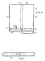
- each wire 15 is fixedly connected with the central rod 5 of the three rods 5 enclosed by said wire. This is achieved in that the ends of the wire 15 are wound a complete turn about the central rod 5, as is shown more clearly in Fig 7.
- a possible alternative is to fixedly connect each wire 15 with the other rod 5 in the associated link.
- each wire 15 may, between its ends and at at least one point, be fixed to one of the two rods 5 of the associated link.
- the fixing of the wires 15 to the rods 5 can be further strengthened if the rods 5 are formed with circumferential grooves in which the wire ends are wound. Such grooves, or projecting bosses on the rods, safely prevent the wire ends from slipping on the rods 5.
- each wire 15 will at all times be guided by the two rods 5 of its own link, when the links are displaced towards one another in the longitudinal direction of the belt. Consequently, the bottom 2 of the conveyor belt 1 has at all times a substantially flat supporting surface for the products carried on the conveyor belt 1, which means that the wire netting according to the invention does not produce any indentations in the supported products, and that the risk of the products getting stuck in the wire netting is eliminated.
- the wire netting according to the invention is advantageous in that it provides the conveyor belt with a flatter supporting surface, that it is less expensive to manufacture since it consists of but one wire type, and that it facilitates assembly of the conveyor belt.
- each wire 15 may be divided into a number of sections each extending over only a portion of the width of the belt 1.
Landscapes
- Engineering & Computer Science (AREA)
- Mechanical Engineering (AREA)
- Belt Conveyors (AREA)
- Chain Conveyers (AREA)
- Structure Of Belt Conveyors (AREA)
- General Details Of Gearings (AREA)
Claims (6)
- Endloses Förderband für eine Luftbehandlungsanlage, in der das Förderband (1) über einen Teil seiner Länge eine schraubenförmige Bahn verfolgt und einen aus querverlaufenden Stangen (5) und einem Drahtgewebe bestehenden Boden (2) und paarweise mit zwei Stangen (5) fest verbundene Seitenplatten (3) umfasst, um zusammen mit diesen Stangen ein Glied zu bilden, das gegenüber benachbarten Gliedern um zwei rechtwinklig zur Bandlängsrichtung sich erstreckende Achsen bewegbar ist, wobei die eine Achse in der Ebene des Bodens (2) liegt und die andere Achse rechtwinklig dazu verläuft, dadurch gekennzeichnet, dass das Drahtgewebe aus Zickzackdrähten (15) besteht, die jeweils nicht nur die beiden Stangen (5) eines Glieds sondern auch eine angrenzende Stange (5) des benachbarten Glieds umschliessen.
- Förderband nach Anspruch 1, dadurch gekennzeichnet, dass die Enden jedes Drahts (15) an einer der beiden Stangen (5) des jeweiligen Glieds befestigt sind.
- Förderband nach Anspruch 2, dadurch gekennzeichnet, dass die Enden jedes Drahts (15) an der mittleren der drei vom genannten Draht umschlossenen Stangen (5) befestigt sind.
- Förderband nach Anspruch 2 oder 3, dadurch gekennzeichnet, dass jeder Draht (15), zwischen seinen Enden an wenigstens einem Punkt, an einer der beiden Stangen (5) des jeweiligen Glieds befestigt ist.
- Förderband nach einem der Ansprüche 1-4, dadurch gekennzeichnet, dass die Seitenplatten (3) jedes Glieds einen Teil (7) aufweisen, der die entsprechenden Seitenplatten (3) eines benachbarten Glieds überlappt und ein langgestrecktes Loch (12) aufweist, durch welches die eine Stange (5) des benachbarten Glieds hindurchläuft.
- Förderband nach einem der Ansprüche 1-5, dadurch gekennzeichnet, dass die Seitenplatten (3) der Glieder als Distanzhalter dienen, deren obere Kantenabschnitte (4) die Glieder einer darüberliegenden Windung in der schraubenförmigen Bahn des Förderbands tragen.
Applications Claiming Priority (2)
| Application Number | Priority Date | Filing Date | Title |
|---|---|---|---|
| SE8902310 | 1989-06-27 | ||
| SE8902310A SE469752B (sv) | 1989-06-27 | 1989-06-27 | Transportband foer luftbehandlingsanlaeggning daer traadnaetet utgoers av sicksackformade traadar |
Publications (2)
| Publication Number | Publication Date |
|---|---|
| EP0479936A1 EP0479936A1 (de) | 1992-04-15 |
| EP0479936B1 true EP0479936B1 (de) | 1993-10-06 |
Family
ID=20376398
Family Applications (1)
| Application Number | Title | Priority Date | Filing Date |
|---|---|---|---|
| EP90917829A Expired - Lifetime EP0479936B1 (de) | 1989-06-27 | 1990-06-26 | Förderband |
Country Status (9)
| Country | Link |
|---|---|
| US (1) | US5190143A (de) |
| EP (1) | EP0479936B1 (de) |
| JP (1) | JPH05500349A (de) |
| AU (1) | AU627605B2 (de) |
| CA (1) | CA2063261A1 (de) |
| DE (1) | DE69003814T2 (de) |
| ES (1) | ES2044620T3 (de) |
| SE (1) | SE469752B (de) |
| WO (1) | WO1991000233A1 (de) |
Families Citing this family (23)
| Publication number | Priority date | Publication date | Assignee | Title |
|---|---|---|---|---|
| US5346057A (en) * | 1992-10-30 | 1994-09-13 | Philip Morris Incorporated | Conveyor belt for treatment of particulate solid material |
| US5350056A (en) * | 1993-06-16 | 1994-09-27 | Cambridge, Inc. | Self-supporting conveyor belt with wire-formed spacers |
| US5460260A (en) * | 1994-06-22 | 1995-10-24 | York International Corporation | Helical conveyor |
| SE504656C2 (sv) * | 1995-07-03 | 1997-03-24 | Frigoscandia Equipment Ab | Transportband |
| US5803232A (en) * | 1996-09-06 | 1998-09-08 | Frigoscandia Equipment Ab | Conveyor belt |
| US5950807A (en) * | 1997-02-20 | 1999-09-14 | Wire Belt Company Of America | Wire belt with variable spacing and method of making |
| US5908106A (en) * | 1997-07-29 | 1999-06-01 | Wire Belt Company Of America | Wire belt splice edge connector |
| US6102196A (en) * | 1998-01-19 | 2000-08-15 | Wire Belt Company Of America | Wire link connection system and method |
| SE520136C2 (sv) | 1998-12-08 | 2003-05-27 | Aga Ab | Flexibelt transportband, klimatkammare innefattande ett sådant band, samt sättet att föra gasen i kammaren |
| DK174134B1 (da) | 1999-06-01 | 2002-07-08 | Colding Kristensen Peter | Transportør |
| US6796420B2 (en) | 2001-10-23 | 2004-09-28 | Richard K. Byrne | Self-stacking conveyor belt and method |
| SE524865C2 (sv) * | 2002-07-08 | 2004-10-12 | Frigoscandia Equipment Ab | Ledat ändlöst transportband för ett luftbehandlingssystem |
| ATE348062T1 (de) * | 2003-07-17 | 2007-01-15 | Ashworth Jonge Poerink Bv | Glied zur verbindung von stangen eines um einer angetriebenen trommel spiralförmig gewickelten förderbands, föderband und förderer mit solchen gliedern |
| US7258226B2 (en) * | 2003-10-14 | 2007-08-21 | The Boc Group, Inc. | Self-stacking spiral conveyor with modular drive system |
| US7347316B2 (en) * | 2003-10-21 | 2008-03-25 | Heber Gerald J | Spiral conveyor belt drive system |
| US7270231B2 (en) * | 2005-05-26 | 2007-09-18 | Heber Gerald J | Self-stacking spiral conveyor belt |
| ATE523452T1 (de) * | 2005-09-30 | 2011-09-15 | Cambridge Int Inc | Drahtförderband mit spannungsübertragung |
| SE1051354A1 (sv) * | 2010-12-21 | 2012-06-19 | John Bean Technologies Ab | Förbättrat sidoplattelement för ett länkorgan i ett självstaplande ändlöst transportband |
| EP3624950A4 (de) * | 2017-05-17 | 2021-06-16 | Laitram, L.L.C. | Zentrifugales entwässerungsfördersystem |
| US10233023B1 (en) * | 2017-09-15 | 2019-03-19 | Ashworth Bros., Inc. | Conveyor belt spiral overlay having intermediate loops |
| JP7808318B2 (ja) * | 2021-12-20 | 2026-01-29 | 株式会社森機械製作所 | バランスネット |
| EP4253286B1 (de) * | 2022-03-28 | 2026-01-07 | Frans Bakker Beheer B.V. | Förderband und vorrichtung zum arretieren einer stange an einem glied eines solchen förderbandes |
| US20250074708A1 (en) * | 2023-08-22 | 2025-03-06 | Ricardo Pio Barakat Biscioni | Spiral conveyor system with direct cage engagement |
Citations (1)
| Publication number | Priority date | Publication date | Assignee | Title |
|---|---|---|---|---|
| SE437008B (sv) * | 1982-11-26 | 1985-02-04 | Frigoscandia Contracting Ab | Transportband |
Family Cites Families (10)
| Publication number | Priority date | Publication date | Assignee | Title |
|---|---|---|---|---|
| US208198A (en) * | 1878-09-17 | Improvement in wire belting | ||
| US2292663A (en) * | 1941-09-12 | 1942-08-11 | Audubon Wire Cloth Corp | Wire belt structure |
| US2769531A (en) * | 1953-05-05 | 1956-11-06 | Audubon Wire Cloth Corp Of New | Woven wire conveyer belt |
| US3202387A (en) * | 1963-12-06 | 1965-08-24 | Cambridge Wire Cloth | Woven wire conveyor belt |
| US3300030A (en) * | 1965-02-16 | 1967-01-24 | Manganese Steel Forge Company | Conveyor belt |
| US3542188A (en) * | 1968-10-11 | 1970-11-24 | Clark Mills Kinney Jr | Rod reinforced type conveyor belt |
| US3563366A (en) * | 1969-03-20 | 1971-02-16 | Cambridge Wire Cloth | Compound rod-reinforced belt |
| SE381241B (sv) * | 1973-03-07 | 1975-12-01 | Frigoscandia Contracting Ab | Transportanordning med ett endlost transportband vilket er anordnat att till en del av sin lengd folja en bana bestaende av ett antal over varandra belegna skruvformigt forlopande varv |
| SE452590B (sv) * | 1985-12-27 | 1987-12-07 | Frigoscandia Contracting Ab | Transportband |
| US4867301A (en) * | 1987-08-10 | 1989-09-19 | Ashworth Bros., Inc. | Conveyor belt and system for single direction lateral curved travel |
-
1989
- 1989-06-27 SE SE8902310A patent/SE469752B/sv not_active IP Right Cessation
-
1990
- 1990-06-26 DE DE90917829T patent/DE69003814T2/de not_active Expired - Fee Related
- 1990-06-26 AU AU59491/90A patent/AU627605B2/en not_active Ceased
- 1990-06-26 EP EP90917829A patent/EP0479936B1/de not_active Expired - Lifetime
- 1990-06-26 ES ES90917829T patent/ES2044620T3/es not_active Expired - Lifetime
- 1990-06-26 CA CA002063261A patent/CA2063261A1/en not_active Abandoned
- 1990-06-26 JP JP2509487A patent/JPH05500349A/ja active Pending
- 1990-06-26 WO PCT/SE1990/000455 patent/WO1991000233A1/en not_active Ceased
- 1990-06-26 US US07/836,018 patent/US5190143A/en not_active Expired - Fee Related
Patent Citations (1)
| Publication number | Priority date | Publication date | Assignee | Title |
|---|---|---|---|---|
| SE437008B (sv) * | 1982-11-26 | 1985-02-04 | Frigoscandia Contracting Ab | Transportband |
Also Published As
| Publication number | Publication date |
|---|---|
| SE8902310L (sv) | 1990-12-28 |
| JPH05500349A (ja) | 1993-01-28 |
| EP0479936A1 (de) | 1992-04-15 |
| SE469752B (sv) | 1993-09-06 |
| SE8902310D0 (sv) | 1989-06-27 |
| DE69003814D1 (de) | 1993-11-11 |
| US5190143A (en) | 1993-03-02 |
| WO1991000233A1 (en) | 1991-01-10 |
| AU5949190A (en) | 1991-01-17 |
| DE69003814T2 (de) | 1994-04-28 |
| CA2063261A1 (en) | 1990-12-28 |
| ES2044620T3 (es) | 1994-01-01 |
| AU627605B2 (en) | 1992-08-27 |
Similar Documents
| Publication | Publication Date | Title |
|---|---|---|
| EP0479936B1 (de) | Förderband | |
| SU1746877A3 (ru) | Бесконечна конвейерна лента | |
| EP1009691B1 (de) | Drahtgewebe-band für dreidimensionale transportstrecken | |
| EP0293095B1 (de) | Wendelförderer | |
| EP0850857B1 (de) | Förderband mit Spiralschichten | |
| EP2871144B1 (de) | Förderband mit unterschiedlichen Abständen mit angehefteten Stangenenden | |
| US4603776A (en) | Conveyor belt | |
| RU99106803A (ru) | Сплетенная из проволоки лента, следующая по криволинейному пути в трех измерениях | |
| US8820517B2 (en) | Lateral plate element for a link included in a self-stacking endless conveyor belt | |
| KR101112168B1 (ko) | 모듈형 플라스틱 컨베이어 벨트 | |
| EP1883593B1 (de) | Selbststapelndes wendelförmiges förderband | |
| EP0702657A1 (de) | Selbsttragender bandförderer mit abstandhaltern aus metallischem draht | |
| RU2015089C1 (ru) | Бесконечная конвейерная лента для установок по обработке транспортируемого груза воздухом | |
| EP1047618A1 (de) | Ein drahtgeflechtförderband | |
| US6796420B2 (en) | Self-stacking conveyor belt and method | |
| US20250388407A1 (en) | Wear-resistant wire-mesh metal-belt conveyors | |
| WO1997002196A1 (en) | Conveyor belt | |
| WO1995016627A1 (en) | Belt conveyor |
Legal Events
| Date | Code | Title | Description |
|---|---|---|---|
| PUAI | Public reference made under article 153(3) epc to a published international application that has entered the european phase |
Free format text: ORIGINAL CODE: 0009012 |
|
| 17P | Request for examination filed |
Effective date: 19920120 |
|
| AK | Designated contracting states |
Kind code of ref document: A1 Designated state(s): DE DK ES FR GB IT NL |
|
| 17Q | First examination report despatched |
Effective date: 19921202 |
|
| GRAA | (expected) grant |
Free format text: ORIGINAL CODE: 0009210 |
|
| AK | Designated contracting states |
Kind code of ref document: B1 Designated state(s): DE DK ES FR GB IT NL |
|
| PG25 | Lapsed in a contracting state [announced via postgrant information from national office to epo] |
Ref country code: DK Effective date: 19931006 |
|
| ITF | It: translation for a ep patent filed | ||
| REF | Corresponds to: |
Ref document number: 69003814 Country of ref document: DE Date of ref document: 19931111 |
|
| REG | Reference to a national code |
Ref country code: ES Ref legal event code: FG2A Ref document number: 2044620 Country of ref document: ES Kind code of ref document: T3 |
|
| ET | Fr: translation filed | ||
| PLBE | No opposition filed within time limit |
Free format text: ORIGINAL CODE: 0009261 |
|
| STAA | Information on the status of an ep patent application or granted ep patent |
Free format text: STATUS: NO OPPOSITION FILED WITHIN TIME LIMIT |
|
| 26N | No opposition filed | ||
| PGFP | Annual fee paid to national office [announced via postgrant information from national office to epo] |
Ref country code: GB Payment date: 19980605 Year of fee payment: 9 Ref country code: DE Payment date: 19980605 Year of fee payment: 9 |
|
| PGFP | Annual fee paid to national office [announced via postgrant information from national office to epo] |
Ref country code: ES Payment date: 19980608 Year of fee payment: 9 |
|
| PGFP | Annual fee paid to national office [announced via postgrant information from national office to epo] |
Ref country code: FR Payment date: 19980611 Year of fee payment: 9 |
|
| PGFP | Annual fee paid to national office [announced via postgrant information from national office to epo] |
Ref country code: NL Payment date: 19980612 Year of fee payment: 9 |
|
| PG25 | Lapsed in a contracting state [announced via postgrant information from national office to epo] |
Ref country code: GB Free format text: LAPSE BECAUSE OF NON-PAYMENT OF DUE FEES Effective date: 19990626 |
|
| PG25 | Lapsed in a contracting state [announced via postgrant information from national office to epo] |
Ref country code: ES Free format text: THE PATENT HAS BEEN ANNULLED BY A DECISION OF A NATIONAL AUTHORITY Effective date: 19990628 |
|
| PG25 | Lapsed in a contracting state [announced via postgrant information from national office to epo] |
Ref country code: FR Free format text: THE PATENT HAS BEEN ANNULLED BY A DECISION OF A NATIONAL AUTHORITY Effective date: 19990630 |
|
| PG25 | Lapsed in a contracting state [announced via postgrant information from national office to epo] |
Ref country code: NL Free format text: LAPSE BECAUSE OF NON-PAYMENT OF DUE FEES Effective date: 20000101 |
|
| GBPC | Gb: european patent ceased through non-payment of renewal fee |
Effective date: 19990626 |
|
| NLV4 | Nl: lapsed or anulled due to non-payment of the annual fee |
Effective date: 20000101 |
|
| PG25 | Lapsed in a contracting state [announced via postgrant information from national office to epo] |
Ref country code: DE Free format text: LAPSE BECAUSE OF NON-PAYMENT OF DUE FEES Effective date: 20000503 |
|
| REG | Reference to a national code |
Ref country code: FR Ref legal event code: ST |
|
| REG | Reference to a national code |
Ref country code: ES Ref legal event code: FD2A Effective date: 20020304 |
|
| PG25 | Lapsed in a contracting state [announced via postgrant information from national office to epo] |
Ref country code: IT Free format text: LAPSE BECAUSE OF NON-PAYMENT OF DUE FEES Effective date: 20050626 |