EP0480064B1 - Antennenelement - Google Patents
Antennenelement Download PDFInfo
- Publication number
- EP0480064B1 EP0480064B1 EP91908459A EP91908459A EP0480064B1 EP 0480064 B1 EP0480064 B1 EP 0480064B1 EP 91908459 A EP91908459 A EP 91908459A EP 91908459 A EP91908459 A EP 91908459A EP 0480064 B1 EP0480064 B1 EP 0480064B1
- Authority
- EP
- European Patent Office
- Prior art keywords
- antenna element
- hollow pipe
- element according
- metal
- metal bar
- Prior art date
- Legal status (The legal status is an assumption and is not a legal conclusion. Google has not performed a legal analysis and makes no representation as to the accuracy of the status listed.)
- Expired - Lifetime
Links
Images

Classifications
-
- H—ELECTRICITY
- H01—ELECTRIC ELEMENTS
- H01Q—ANTENNAS, i.e. RADIO AERIALS
- H01Q7/00—Loop antennas with a substantially uniform current distribution around the loop and having a directional radiation pattern in a plane perpendicular to the plane of the loop
- H01Q7/06—Loop antennas with a substantially uniform current distribution around the loop and having a directional radiation pattern in a plane perpendicular to the plane of the loop with core of ferromagnetic material
- H01Q7/08—Ferrite rod or like elongated core
Definitions
- This invention relates to antenna elements, and, more specifically, it relates to an antenna element comprising a core which comprises a hollow pipe made of a magnetic material and a metal bar made of aluminum, titanium, copper, or an alloy of those metals, and a wire of electrically conductive material which is wound on a surface of the core.
- each unit of traditional antennas suites to a limited range of wave length, so that two antennas are necessary to receive VHF and UHF waves for TV, where very careful adjustments of the length of antenna elements is very essential. This leads to complication and high costs of receiving units.
- plane antennas or print antennas for receiving satellite broadcasting and/or for mobility communication that offer smaller size than the parabola antenna, have been commercially available.
- Such antennas also have a limitation to minituarize maintaining its performance.
- JP-B-44-14850 a ferro-magnetic antenna that receives ulta-short waves and radio waves.
- This ferro-magnetic antenna comprises a ferro-magnetic body, a first conductor that is wound around the outer periphery of said ferro-magnetic body and a second conductor that is inserted in said ferro-magnetic body and in which the impedance of said first conductor is matched to a load impedance by connecting one end of said second conductor whose upper end is grounded to one end of said first conductor, whose other end is made open.
- This coil antenna for a radio apparatus is known.
- This coil antenna comprises an elongated ferro-magnetic element, an axially associated conductive member and a conductive winding surrounding but insulated from said ferro-magnetic element.
- the invention relates to an antenna element as referred to in claim 1.
- the object of this invention is to provide a small sized and light antenna element which has high fidelity and less directivity, and suits to wide range wave length.
- an antenna element comprising a core which comprises a hollow pipe made of a magnetic material, a metal bar made of aluminum, titanium, copper or an alloy thereof and being inserted into the hollow pipe, and an insulating material existing between the hollow pipe and the metal bar; and an electrically conductive wire which is wound on a surface of the core can achieve the above object.
- This invention is based on the above finding.
- the antenna element of the present invention is characterized in that it comprises a hollow pipe made of a magnetic material said hollow pipe having an axial bore extending therethrough; a solid or hollow metal bar made of at least one metal selected from the group consisting of aluminum, titanium, copper and alloys thereof, said metal bar being inserted into the axial bore; an insulating material existing between the hollow pipe and the metal bar; and an electrically conductive wire being wound on at least a part of an outer surface of the hollow pipe, said electrically conductive wire having been coated with an insulating material.
- the magnetic materials to be used for this invention are preferably those with high magnetic permeability, with less sensitivity to the frequency of electromagnetic wave, with high saturation magnetic flux density, with less coercive force, and with magnetostriction, and more preferably having a maximum magnetic permeability of about 100,000 ⁇ max or more, and most preferably about 500,000 ⁇ max or more. Using the magnetic materials with higher permeability and less sensitivity to frequency, the performance of the antenna tends to be improved.
- Amorphous metals to be used for this invention are preferably iron-based or cobalt-based amorphous metals, and more preferably amorphous metals of Co-Fe-Ni-B-Si type, Co-Fe-Ni-Mo-B-Si type, Co-Fe-Si-B type, Fe-B-Si type, and Fe-Ni-Mo-B type.
- This invention may use any of amorphous metals made by liquid phase method such as liquid quenching, gas phase method such as spattering, or plating method;
- the shape of the magnetic material is not specially designed but to be a hollow pipe shape having an axial bore in which a metal bar described later is inserted
- the structure of the hollow pipe made of the magnetic material is also flexible.
- the hollow pipe may be a simple body, and, in a case where a magnetic material, such as an amorphous metal, being difficult of shaping to a hollow pipe in a simple body is used, the hollow pipe may preferably consist of multiple fibers, bars or strips of a magnetic material, or may be preferably formed by rolling a sheet-shaped magnetic material.
- the hollow pipe made of the magnetic material is formed by rolling an insulating film, such as polyester film, on which the multiple numbers of fiber-, bar-or strip-shaped magnetic materials have been laid in parallel, since said hollow pipe can be easily produced by the method.
- the diameter of a fiber-or bar-shaped magnetic material is preferred to be 500 ⁇ m or less, and most preferably 25 ⁇ m or less. Further the thickness of a fine plate-or sheet-shaped magnetic material is preferably 500 ⁇ m or less, and most preferably 25 ⁇ m or less. Smaller sized magnetic material leads to less sensitivity of permeability to frequency.
- the material of the metal bar to be inserted in above pipe is at least one metal selected from the group of aluminum, titanium, copper and alloys thereof.
- An aluminum bar preferably achieves less weight and less cost.
- the bar should be inserted into the hollow pipe, and an insulation material should exist between the pipe and the bar.
- the diameter of the bar is preferred to be approximately close to inner diameter of the pipe.
- the bar can be solid or hollow, and a metal pipe, especially aluminum pipe is recommended to minimize antenna element weight.
- an antenna element of the present invention for VHF and UHF prefers the length of metal bar of 10 - 2,000 mm, most preferably 200 - 500 mm, and that of hollow pipe of longer than 10 mm and shorter than the bar length, most preferably 50 - 200 mm.
- An antenna element having the total length of longer than 2,000 mm achieves high performance for low frequency waves but has strong directivity.
- An antenna element using a hollow pipe of shorter than 10 mm or a metal bar of shorter than 10 mm does not tend to show advantages of this invention.
- a core of the antenna element of the present invention comprises the hollow pipe made of a magnetic material, the metal bar being inserted into said hollow pipe, and an insulating material existing between the hollow pipe and the metal bar to insulate said metal bar from said hollow pipe.
- the insulation material to be used between the hollow pipe and the metal bar does not need any specific requirements, but insulating films of organic high molecular compounds or metal oxides are preferred.
- an electrically conductive wire is wound on at least a part of an outer surface of the hollow pipe.
- the electrically conductive wire can be a conventional one such as aluminum or copper wire coated with a synthetic resin.
- the direction of winding can be clock- or anticlockwise but shall be one direction throughout the length. It is preferably suggested to wind the wire throughout the hollow pipe length without gaps in between. It is possible to wind the wire as multiple layer, and a printed sheet circuit can also be utilized replacing wire.
- At least one end of the electrically conductive wire of the antenna element of the present invention is connected to a receiving unit. It is preferably suggested to connect one end of the wire to the receiving unit, not connecting both ends to decrease noise level
- the connecting end is recommended to be the lead wire from the antenna end, where positions of the hollow pipe and the inserted bar is at the same level.
- the antenna element of the present invention can be used as single one, but can also be combined with multiple units of the invented ones or with conventional ones.
- the accessories for convenient usage of the antenna elements of the present invention may be selected, for instance an adopter for easy setting to cars, rubber magnet to use as flat antenna.
- Fig. 1 is a perspective view showing an antenna element manufactured in Example 1
- Fig. 2 is a cross sectional view showing section A of the antenna element shown in Fig. 1
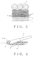
- Fig. 3 is a partial cross sectional view showing section B of the antenna element shown in Fig. 2
- Fig. 4 is a perspective view showing a manufacturing process of the antenna element shown in Fig. 1.
- Fig. 1 is a perspective view showing an antenna element manufactured in Example 1
- Fig. 2 is a cross sectional view showing section A of the antenna element shown in Fig. 1
- Fig. 3 is a partial cross sectional view showing section B of the antenna element shown in Fig. 2
- Fig. 4 is a perspective view showing a manufacturing process of the antenna element shown in Fig. 1.
- an aluminum pipe 1 sized by 6 mm outside diameter, 5 mm inner diameter and 450 mm length was used, an outer surface of which was covered by a commercially available insulation tube 2 (a shrinkable tube made of a synthetic resin) in the width of 200 mm from one edge of pipe 1.
- a commercially available insulation tube 2 a shrinkable tube made of a synthetic resin
- amorphous metal hollow pipe Twenty five (25) pieces of amorphous metal strips 3 sized by 200 mm length, 10 mm width and 25 ⁇ m thickness (made by Allied Inc., USA, Metoglass 2714 A) were laid in parallel on a polyester film 4 (two sheets of 300 - 400 mm length. 200 mm width and 13 ⁇ m thickness). The insulation tube 2 was wrapped by this sheet 4, as shown in Fig. 4, forming a hollow pipe shaped body made of amorphous metal 3 (hereinafter referred to as "amorphous metal hollow pipe").
- the properties of the amorphous metal used are; (Compositions) Co-Fe-Ni-B-Si type (Magnetic properties) Maximum permeability ⁇ max : 1,000,000 Saturation magnetic flux density B s (KG) : 5.5 Magnetostriction ⁇ s ⁇ 10 -6 : ⁇ 1 Curie point Tc (deg C) : 205
- An aluminum wire 5 (1 mm diameter, coated by a synthetic resin insulation material on the surface) was wound on the amorphous metal hollow pipe 3, throughout the length (200 mm total length) from one end to the other, and without gap in between to obtain an antenna element of the present invention.
- One end of the aluminum wire 5 (connected to the end where edges of aluminum pipe 1 and the amorphous metal hollow pipe 3 are at the same level) was connected to a signal level meter (LEADER Signal Level Meter LFC-945, manufactured by Leader Electronic, Inc.) via central electric conductor of coaxial cable 6 (manufactured by Fujikura Co., 2.5C-2V, 4m length). Further, another end of the aluminum wire 5 was kept open.
- a signal level meter LEADER Signal Level Meter LFC-945, manufactured by Leader Electronic, Inc.
- coaxial cable 6 manufactured by Fujikura Co., 2.5C-2V, 4m length
- This antenna element was set in a timber house (3-2-27, Daiganji, Fukui-shi, Fukui-ken, Japan) located at approx. 4 km far from a broad casting antenna of a TV station, where no obstacles are existing.
- Received signal level of TV set with wave specifications are listed in Table 1, where three cases of antenna axis direction, vertical position (V), horizontally directed to broad casting antenna (H 0 ) and turned by 90 degree (H 90 ), were compared.
- the insulating-coated surface of this aluminum pipe was wrapped by an amorphous metal sheet (manufactured by Allied Inc., USA, Metoglass 2714 A) sized by 100 mm length, 50 mm width and 25 ⁇ m thickness, and further wound by a copper wire (1 mm diameter, coated by insulation synthetic resin) as the same manner as Example 1 to obtain an antenna element of the present invention.
- amorphous metal sheet manufactured by Allied Inc., USA, Metoglass 2714 A
- the antenna element was tested as the same manner as for Example 1. The results are listed in Table 1.
- Example 1 The aluminum pipe used in Example 1 was only used as the antenna element in this case. That is, the coaxial conductive wire used in Example 1 was connected to one end of the aluminum pipe directly, and the same tests were carried out. The results are shown in Table 1.
- a conventional TV antenna for automobiles (manufactured by Clarion, Inc., ZCA-301, two rod antenna elements sized by 2 mm diameter and 400 mm length) was used for this Comparative Example. Test conditions and procedures were the same as those for Example 1, and the results are also listed in Table 1.
- the conventional antenna for automobiles shows sharp directivity and receiving level for UHF range is not sufficient. It was not possible to improve the performance even adjusting positions of two antenna elements.
- the antenna elements of the present invention had high sensitivity for wide range from VHF to UHF waves. Further, the antenna elements of the present invention had very week directivity, and therefore, they enabled to receive the waves excellently regardless of direction of the antenna elements. By using of the antenna elements of the present invention, the images on TV screen and voices were received excellently for all of the channels.
- the antenna elements of the present invention are characterized with small sized, less weight, and high sensitivity with less directivity for wide range of wave frequency. Therefore, each of those antenna elements enables to receive VHF and UHF waves excellently with single antenna element.
Landscapes
- Details Of Aerials (AREA)
- Soft Magnetic Materials (AREA)
Claims (12)
- Ein Antennenelement, das folgendes aufweist:
ein hohles Rohr (3) mit einer sich dahindurch erstreckenden Axialbohrung; eine massive oder hohle Metallstange (1) hergestellt aus mindestens einem Metall, welches aus der Aluminium, Titan, Kupfer und Legierungen davon enthaltenen Gruppe ausgewählt ist, wobei die Metallstange (1) in die Axialbohrung eingesetzt ist; ein Isoliermaterial (2) angeordnet zwischen dem hohlen Rohr (3) und der Metallstange (1); und ein elektrisch leitender Draht (5), der auf mindestens einen Teil einer Außenoberfläche des hohlen Rohrs (3) gewickelt ist,
dadurch gekennzeichnet, daß das Antennenelement zum Empfang von Signalen in den VHF und UHF-Bändern verwendet wird, daß das hohle Rohr (3) aus einem amorphen magnetischen Material hergestellt ist, daß der erwähnte elektrisch leitende Draht (5) mit einem Isoliermaterial beschichtet oder überzogen ist und daß die Metallstange (1) weder mit dem elektrisch leitenden Draht (5) verbunden noch geerdet ist. - Antennenelement nach Anspruch 1, wobei das hohle Rohr (3) aus einem aus einem flächenförmigen amorphen Metall besteht, das gerollt oder gewalzt wurde.
- Antennenelement nach Anspruch 1, wobei das hohle Rohr (3) aus mehrfachen Anzahlen von faser-, stangen- oder streifen- förmigen amorphen Metallen besteht.
- Antennenelement nach Anspruch 1, wobei das hohle Rohr (3) aus mehrfachen Anzahlen von faser-, stangen- oder streifen- förmigen amorphen Metallen und einer Isolierschicht (4) besteht, auf die die amorphen Metalle parallel aufgelegt wurden und das gerollt oder gewalzt wurde.
- Antennenelement nach Anspruch 1, wobei das amorphe Metall als eine Eigenschaft eine maximale magnetische Permeabilität von mehr als 100000 µmax besitzt.
- Antennenelement nach Anspruch 1, wobei die Metallstange (1) eine Länge von 10 bis 2000 mm besitzt und wobei das hohle Rohr (3) eine Länge von mehr als 10 mm besitzt und kleiner ist als die Länge der Metallstange.
- Antennenelement nach Anspruch 1, wobei die Metallstange (1) eine Länge von 200 bis 500 mm besitzt und wobei das hohle Rohr (3) eine Länge von 50 bis 200 mm besitzt.
- Antennenelement nach Anspruch 1, wobei die Metallstange (1) eine hohle oder massive Aluminiumstange ist.
- Antennenelement nach Anspruch 1, wobei das Isoliermaterial (2) angeordnet zwischen dem hohlen Rohr und der Metallstange eine Isolierschicht oder ein Isolierfilm ist und zwar hergestellt aus einer organischen Polymerverbindung oder einem Metalloxid.
- Antennenelement nach Anspruch 1, wobei ein Ende des elektrisch leitenden Drahtes (5) ein Anschluß ist, der mit einer Empfangseinheit verbindbar ist und wobei ein weiteres Ende ein Anschluß ist, der offen gelassen werden kann.
- Antennenelement nach Anspruch 1, wobei eine Kante des hohlen Rohrs (3) und die entsprechende Kante der Metallstange (1) auf gleiches Niveau gebracht oder darauf ausgerichtet sind.
- Antennenelement nach Anspruch 11, wobei ein Ende des elektrisch leitenden Drahtes (5), welches den auf ein Niveau gebrachten Kanten entspricht, einen Anschluß bildet, der mit einer Empfangseinheit verbindbar ist, und daß das andere Ende des Drahtes (5) ein offen zu haltender Anschluß ist.
Applications Claiming Priority (3)
| Application Number | Priority Date | Filing Date | Title |
|---|---|---|---|
| JP110355/90 | 1990-04-27 | ||
| JP2110355A JP2559074B2 (ja) | 1990-04-27 | 1990-04-27 | アンテナ素子 |
| PCT/JP1991/000543 WO1991017584A1 (fr) | 1990-04-27 | 1991-04-23 | Element d'antenne |
Publications (3)
| Publication Number | Publication Date |
|---|---|
| EP0480064A1 EP0480064A1 (de) | 1992-04-15 |
| EP0480064A4 EP0480064A4 (en) | 1992-06-10 |
| EP0480064B1 true EP0480064B1 (de) | 1996-08-21 |
Family
ID=14533672
Family Applications (1)
| Application Number | Title | Priority Date | Filing Date |
|---|---|---|---|
| EP91908459A Expired - Lifetime EP0480064B1 (de) | 1990-04-27 | 1991-04-23 | Antennenelement |
Country Status (5)
| Country | Link |
|---|---|
| US (1) | US5220338A (de) |
| EP (1) | EP0480064B1 (de) |
| JP (1) | JP2559074B2 (de) |
| DE (1) | DE69121505T2 (de) |
| WO (1) | WO1991017584A1 (de) |
Families Citing this family (17)
| Publication number | Priority date | Publication date | Assignee | Title |
|---|---|---|---|---|
| DE69220029T2 (de) * | 1992-02-05 | 1997-09-18 | Texas Instruments Inc | Verfahren zur Herstellung eines flachen, flexiblen Antennenkerns für einen Chip-Transponder, eingebaut in einer Karte oder ähnlichem Objekt und ein derart hergestellter Antennenkern |
| DE69418536T2 (de) * | 1993-06-21 | 2000-03-02 | Raytheon Co., Lexington | Radarsystem und zugehörige Komponenten zum Senden eines elektromagnetischen Unterwassersignals |
| JP3891448B2 (ja) * | 1994-04-11 | 2007-03-14 | 日立金属株式会社 | 薄型アンテナおよびそれを用いたカード |
| US5886672A (en) * | 1997-01-29 | 1999-03-23 | Innotek Pet Products, Inc. | Collapsible antenna |
| JP4128721B2 (ja) | 2000-03-17 | 2008-07-30 | 株式会社東芝 | 情報記録物品 |
| US6844727B2 (en) * | 2000-06-28 | 2005-01-18 | Baker Hughes Incorporated | Method and apparatus of reducing ringing in a nuclear magnetic resonance probe |
| US7235970B2 (en) * | 2000-06-28 | 2007-06-26 | Baker Hughes Incorporated | Antenna core material for use in MWD resistivity measurements and NMR measurements |
| US7978078B2 (en) * | 2001-12-21 | 2011-07-12 | Sensormatic Electronics, LLC | Magnetic core transceiver for electronic article surveillance marker detection |
| JP2003218620A (ja) * | 2002-01-24 | 2003-07-31 | Hitachi Cable Ltd | 平板アンテナの製造方法 |
| US7091858B2 (en) * | 2003-01-14 | 2006-08-15 | Sensormatic Electronics Corporation | Wide exit electronic article surveillance antenna system |
| US7420463B2 (en) * | 2003-01-14 | 2008-09-02 | Sensormatic Electronics Corporation | Wide exit electronic article surveillance antenna system |
| DE10302646B4 (de) * | 2003-01-23 | 2010-05-20 | Vacuumschmelze Gmbh & Co. Kg | Antennenkern und Verfahren zum Herstellen eines Antennenkerns |
| US7167140B2 (en) * | 2003-07-02 | 2007-01-23 | Nec Tokin Corporation | Coil antenna |
| DE602004015075D1 (de) * | 2004-04-27 | 2008-08-28 | Nec Tokin Corp | Spulenantenne |
| JP3964401B2 (ja) * | 2004-04-27 | 2007-08-22 | Necトーキン株式会社 | アンテナ用コア、コイルアンテナ、時計、携帯電話機、電子装置 |
| JP2008264511A (ja) * | 2007-03-27 | 2008-11-06 | Tomiko Shibano | 履き物 |
| JP4999795B2 (ja) * | 2008-07-18 | 2012-08-15 | 三菱電機株式会社 | 伝送路及びそれを用いた車両内通信システム |
Citations (1)
| Publication number | Priority date | Publication date | Assignee | Title |
|---|---|---|---|---|
| JPH05193849A (ja) * | 1991-07-26 | 1993-08-03 | Inventio Ag | エレベータ用の表面取付型表示素子 |
Family Cites Families (10)
| Publication number | Priority date | Publication date | Assignee | Title |
|---|---|---|---|---|
| BE507544A (de) * | 1951-12-04 | |||
| JPS5193849A (de) * | 1975-02-17 | 1976-08-17 | ||
| US4205318A (en) * | 1979-01-15 | 1980-05-27 | Pisano Vincent F | Mini-indoor TV antenna |
| DE3036084A1 (de) * | 1980-09-25 | 1982-04-29 | Robert Bosch Gmbh, 7000 Stuttgart | Stabantenne, insbesondere fuer ukw-rundfunkempfang |
| US4442438A (en) * | 1982-03-29 | 1984-04-10 | Motorola, Inc. | Helical antenna structure capable of resonating at two different frequencies |
| US4458248A (en) * | 1982-04-26 | 1984-07-03 | Haramco Research, Inc. | Parametric antenna |
| JPS6050510U (ja) * | 1983-09-13 | 1985-04-09 | ティーディーケイ株式会社 | アンテナコイル |
| US5081469A (en) * | 1987-07-16 | 1992-01-14 | Sensormatic Electronics Corporation | Enhanced bandwidth helical antenna |
| JPH02223205A (ja) * | 1988-11-02 | 1990-09-05 | Kurieiteitsuku Japan:Kk | アンテナ |
| US5065138A (en) * | 1990-08-03 | 1991-11-12 | Security Tag Systems, Inc. | Magnetically-coupled two-resonant-circuit, frequency divider for presence-detection-system tag |
-
1990
- 1990-04-27 JP JP2110355A patent/JP2559074B2/ja not_active Expired - Lifetime
-
1991
- 1991-04-23 EP EP91908459A patent/EP0480064B1/de not_active Expired - Lifetime
- 1991-04-23 US US07/778,823 patent/US5220338A/en not_active Expired - Fee Related
- 1991-04-23 DE DE69121505T patent/DE69121505T2/de not_active Expired - Fee Related
- 1991-04-23 WO PCT/JP1991/000543 patent/WO1991017584A1/ja not_active Ceased
Patent Citations (1)
| Publication number | Priority date | Publication date | Assignee | Title |
|---|---|---|---|---|
| JPH05193849A (ja) * | 1991-07-26 | 1993-08-03 | Inventio Ag | エレベータ用の表面取付型表示素子 |
Also Published As
| Publication number | Publication date |
|---|---|
| WO1991017584A1 (fr) | 1991-11-14 |
| JPH0410701A (ja) | 1992-01-14 |
| EP0480064A1 (de) | 1992-04-15 |
| US5220338A (en) | 1993-06-15 |
| DE69121505D1 (de) | 1996-09-26 |
| DE69121505T2 (de) | 1997-04-03 |
| JP2559074B2 (ja) | 1996-11-27 |
| EP0480064A4 (en) | 1992-06-10 |
Similar Documents
| Publication | Publication Date | Title |
|---|---|---|
| EP0480064B1 (de) | Antennenelement | |
| US5220339A (en) | Antenna having a core of an amorphous material | |
| US5189435A (en) | Retractable motorized multiband antenna | |
| US5923298A (en) | Multiband reception antenna for terrestrial digital audio broadcast bands | |
| EP0951023B1 (de) | Magnetischer Kompositartikel zur Unterdrückung von elektromagnetischen Interferenzen | |
| JP2538140B2 (ja) | 車両用ガラスアンテナ | |
| EP2434579B1 (de) | Antennenvorrichtung | |
| AU664079B2 (en) | Antenna for vehicle window | |
| JP2003502894A (ja) | 多帯域アンテナ | |
| EP2571099A1 (de) | Kobraantenne | |
| US4318109A (en) | Planar antenna with tightly wound folded sections | |
| US6160518A (en) | Dual-loop multiband reception antenna for terrestrial digital audio broadcasts | |
| WO2000072405A1 (en) | Vehicle antenna assembly for receiving satellite broadcast signals | |
| US5311201A (en) | Multi-band antenna | |
| US20030117339A1 (en) | Composite antenna apparatus | |
| JP2003526977A (ja) | 高周波磁束のためのガイド | |
| JPH07297617A (ja) | ガラスアンテナ | |
| JPS60233904A (ja) | アンテナ装置 | |
| JPH09213528A (ja) | チョークコイル | |
| JPH05136627A (ja) | 移動体用アンテナ | |
| JP2003087031A (ja) | アンテナ | |
| US9774088B1 (en) | Antenna system | |
| EP1592085B1 (de) | Spulenantenne | |
| US6351251B1 (en) | Helical antenna | |
| JP2003087030A (ja) | 車載用アンテナ |
Legal Events
| Date | Code | Title | Description |
|---|---|---|---|
| PUAI | Public reference made under article 153(3) epc to a published international application that has entered the european phase |
Free format text: ORIGINAL CODE: 0009012 |
|
| AK | Designated contracting states |
Kind code of ref document: A1 Designated state(s): DE FR GB |
|
| A4 | Supplementary search report drawn up and despatched |
Effective date: 19920422 |
|
| AK | Designated contracting states |
Kind code of ref document: A4 Designated state(s): DE FR GB |
|
| 17P | Request for examination filed |
Effective date: 19920611 |
|
| 17Q | First examination report despatched |
Effective date: 19940613 |
|
| GRAG | Despatch of communication of intention to grant |
Free format text: ORIGINAL CODE: EPIDOS AGRA |
|
| GRAH | Despatch of communication of intention to grant a patent |
Free format text: ORIGINAL CODE: EPIDOS IGRA |
|
| GRAH | Despatch of communication of intention to grant a patent |
Free format text: ORIGINAL CODE: EPIDOS IGRA |
|
| GRAA | (expected) grant |
Free format text: ORIGINAL CODE: 0009210 |
|
| AK | Designated contracting states |
Kind code of ref document: B1 Designated state(s): DE FR GB |
|
| REF | Corresponds to: |
Ref document number: 69121505 Country of ref document: DE Date of ref document: 19960926 |
|
| ET | Fr: translation filed | ||
| PGFP | Annual fee paid to national office [announced via postgrant information from national office to epo] |
Ref country code: FR Payment date: 19970409 Year of fee payment: 7 |
|
| PGFP | Annual fee paid to national office [announced via postgrant information from national office to epo] |
Ref country code: GB Payment date: 19970414 Year of fee payment: 7 |
|
| PGFP | Annual fee paid to national office [announced via postgrant information from national office to epo] |
Ref country code: DE Payment date: 19970429 Year of fee payment: 7 |
|
| PLBE | No opposition filed within time limit |
Free format text: ORIGINAL CODE: 0009261 |
|
| STAA | Information on the status of an ep patent application or granted ep patent |
Free format text: STATUS: NO OPPOSITION FILED WITHIN TIME LIMIT |
|
| 26N | No opposition filed | ||
| PG25 | Lapsed in a contracting state [announced via postgrant information from national office to epo] |
Ref country code: GB Free format text: LAPSE BECAUSE OF NON-PAYMENT OF DUE FEES Effective date: 19980423 |
|
| PG25 | Lapsed in a contracting state [announced via postgrant information from national office to epo] |
Ref country code: FR Free format text: THE PATENT HAS BEEN ANNULLED BY A DECISION OF A NATIONAL AUTHORITY Effective date: 19980430 |
|
| GBPC | Gb: european patent ceased through non-payment of renewal fee |
Effective date: 19980423 |
|
| PG25 | Lapsed in a contracting state [announced via postgrant information from national office to epo] |
Ref country code: DE Free format text: LAPSE BECAUSE OF NON-PAYMENT OF DUE FEES Effective date: 19990202 |
|
| REG | Reference to a national code |
Ref country code: FR Ref legal event code: ST |