EP0480082B1 - Verfahren und Gerät zum Verengen eines zylindrischen Körpers - Google Patents
Verfahren und Gerät zum Verengen eines zylindrischen Körpers Download PDFInfo
- Publication number
- EP0480082B1 EP0480082B1 EP90119335A EP90119335A EP0480082B1 EP 0480082 B1 EP0480082 B1 EP 0480082B1 EP 90119335 A EP90119335 A EP 90119335A EP 90119335 A EP90119335 A EP 90119335A EP 0480082 B1 EP0480082 B1 EP 0480082B1
- Authority
- EP
- European Patent Office
- Prior art keywords
- cylindrical body
- hollow cylindrical
- grasping members
- drawing die
- grasping
- Prior art date
- Legal status (The legal status is an assumption and is not a legal conclusion. Google has not performed a legal analysis and makes no representation as to the accuracy of the status listed.)
- Expired - Lifetime
Links
Images




Classifications
-
- F—MECHANICAL ENGINEERING; LIGHTING; HEATING; WEAPONS; BLASTING
- F01—MACHINES OR ENGINES IN GENERAL; ENGINE PLANTS IN GENERAL; STEAM ENGINES
- F01N—GAS-FLOW SILENCERS OR EXHAUST APPARATUS FOR MACHINES OR ENGINES IN GENERAL; GAS-FLOW SILENCERS OR EXHAUST APPARATUS FOR INTERNAL-COMBUSTION ENGINES
- F01N13/00—Exhaust or silencing apparatus characterised by constructional features
- F01N13/18—Construction facilitating manufacture, assembly, or disassembly
-
- B—PERFORMING OPERATIONS; TRANSPORTING
- B23—MACHINE TOOLS; METAL-WORKING NOT OTHERWISE PROVIDED FOR
- B23P—METAL-WORKING NOT OTHERWISE PROVIDED FOR; COMBINED OPERATIONS; UNIVERSAL MACHINE TOOLS
- B23P11/00—Connecting or disconnecting metal parts or objects by metal-working techniques not otherwise provided for
- B23P11/005—Connecting or disconnecting metal parts or objects by metal-working techniques not otherwise provided for by expanding or crimping
-
- F—MECHANICAL ENGINEERING; LIGHTING; HEATING; WEAPONS; BLASTING
- F01—MACHINES OR ENGINES IN GENERAL; ENGINE PLANTS IN GENERAL; STEAM ENGINES
- F01N—GAS-FLOW SILENCERS OR EXHAUST APPARATUS FOR MACHINES OR ENGINES IN GENERAL; GAS-FLOW SILENCERS OR EXHAUST APPARATUS FOR INTERNAL-COMBUSTION ENGINES
- F01N3/00—Exhaust or silencing apparatus having means for purifying, rendering innocuous, or otherwise treating exhaust
- F01N3/08—Exhaust or silencing apparatus having means for purifying, rendering innocuous, or otherwise treating exhaust for rendering innocuous
- F01N3/10—Exhaust or silencing apparatus having means for purifying, rendering innocuous, or otherwise treating exhaust for rendering innocuous by thermal or catalytic conversion of noxious components of exhaust
- F01N3/24—Exhaust or silencing apparatus having means for purifying, rendering innocuous, or otherwise treating exhaust for rendering innocuous by thermal or catalytic conversion of noxious components of exhaust characterised by constructional aspects of converting apparatus
- F01N3/28—Construction of catalytic reactors
- F01N3/2839—Arrangements for mounting catalyst support in housing, e.g. with means for compensating thermal expansion or vibration
- F01N3/2842—Arrangements for mounting catalyst support in housing, e.g. with means for compensating thermal expansion or vibration specially adapted for monolithic supports, e.g. of honeycomb type
-
- F—MECHANICAL ENGINEERING; LIGHTING; HEATING; WEAPONS; BLASTING
- F01—MACHINES OR ENGINES IN GENERAL; ENGINE PLANTS IN GENERAL; STEAM ENGINES
- F01N—GAS-FLOW SILENCERS OR EXHAUST APPARATUS FOR MACHINES OR ENGINES IN GENERAL; GAS-FLOW SILENCERS OR EXHAUST APPARATUS FOR INTERNAL-COMBUSTION ENGINES
- F01N2350/00—Arrangements for fitting catalyst support or particle filter element in the housing
-
- F—MECHANICAL ENGINEERING; LIGHTING; HEATING; WEAPONS; BLASTING
- F01—MACHINES OR ENGINES IN GENERAL; ENGINE PLANTS IN GENERAL; STEAM ENGINES
- F01N—GAS-FLOW SILENCERS OR EXHAUST APPARATUS FOR MACHINES OR ENGINES IN GENERAL; GAS-FLOW SILENCERS OR EXHAUST APPARATUS FOR INTERNAL-COMBUSTION ENGINES
- F01N2450/00—Methods or apparatus for fitting, inserting or repairing different elements
- F01N2450/02—Fitting monolithic blocks into the housing
-
- F—MECHANICAL ENGINEERING; LIGHTING; HEATING; WEAPONS; BLASTING
- F01—MACHINES OR ENGINES IN GENERAL; ENGINE PLANTS IN GENERAL; STEAM ENGINES
- F01N—GAS-FLOW SILENCERS OR EXHAUST APPARATUS FOR MACHINES OR ENGINES IN GENERAL; GAS-FLOW SILENCERS OR EXHAUST APPARATUS FOR INTERNAL-COMBUSTION ENGINES
- F01N2470/00—Structure or shape of exhaust gas passages, pipes or tubes
- F01N2470/26—Tubes being formed by extrusion, drawing or rolling
-
- Y—GENERAL TAGGING OF NEW TECHNOLOGICAL DEVELOPMENTS; GENERAL TAGGING OF CROSS-SECTIONAL TECHNOLOGIES SPANNING OVER SEVERAL SECTIONS OF THE IPC; TECHNICAL SUBJECTS COVERED BY FORMER USPC CROSS-REFERENCE ART COLLECTIONS [XRACs] AND DIGESTS
- Y10—TECHNICAL SUBJECTS COVERED BY FORMER USPC
- Y10T—TECHNICAL SUBJECTS COVERED BY FORMER US CLASSIFICATION
- Y10T29/00—Metal working
- Y10T29/49—Method of mechanical manufacture
- Y10T29/49345—Catalytic device making
-
- Y—GENERAL TAGGING OF NEW TECHNOLOGICAL DEVELOPMENTS; GENERAL TAGGING OF CROSS-SECTIONAL TECHNOLOGIES SPANNING OVER SEVERAL SECTIONS OF THE IPC; TECHNICAL SUBJECTS COVERED BY FORMER USPC CROSS-REFERENCE ART COLLECTIONS [XRACs] AND DIGESTS
- Y10—TECHNICAL SUBJECTS COVERED BY FORMER USPC
- Y10T—TECHNICAL SUBJECTS COVERED BY FORMER US CLASSIFICATION
- Y10T29/00—Metal working
- Y10T29/49—Method of mechanical manufacture
- Y10T29/49826—Assembling or joining
- Y10T29/49908—Joining by deforming
-
- Y—GENERAL TAGGING OF NEW TECHNOLOGICAL DEVELOPMENTS; GENERAL TAGGING OF CROSS-SECTIONAL TECHNOLOGIES SPANNING OVER SEVERAL SECTIONS OF THE IPC; TECHNICAL SUBJECTS COVERED BY FORMER USPC CROSS-REFERENCE ART COLLECTIONS [XRACs] AND DIGESTS
- Y10—TECHNICAL SUBJECTS COVERED BY FORMER USPC
- Y10T—TECHNICAL SUBJECTS COVERED BY FORMER US CLASSIFICATION
- Y10T29/00—Metal working
- Y10T29/49—Method of mechanical manufacture
- Y10T29/49826—Assembling or joining
- Y10T29/49908—Joining by deforming
- Y10T29/49925—Inward deformation of aperture or hollow body wall
-
- Y—GENERAL TAGGING OF NEW TECHNOLOGICAL DEVELOPMENTS; GENERAL TAGGING OF CROSS-SECTIONAL TECHNOLOGIES SPANNING OVER SEVERAL SECTIONS OF THE IPC; TECHNICAL SUBJECTS COVERED BY FORMER USPC CROSS-REFERENCE ART COLLECTIONS [XRACs] AND DIGESTS
- Y10—TECHNICAL SUBJECTS COVERED BY FORMER USPC
- Y10T—TECHNICAL SUBJECTS COVERED BY FORMER US CLASSIFICATION
- Y10T29/00—Metal working
- Y10T29/53—Means to assemble or disassemble
- Y10T29/53652—Tube and coextensive core
-
- Y—GENERAL TAGGING OF NEW TECHNOLOGICAL DEVELOPMENTS; GENERAL TAGGING OF CROSS-SECTIONAL TECHNOLOGIES SPANNING OVER SEVERAL SECTIONS OF THE IPC; TECHNICAL SUBJECTS COVERED BY FORMER USPC CROSS-REFERENCE ART COLLECTIONS [XRACs] AND DIGESTS
- Y10—TECHNICAL SUBJECTS COVERED BY FORMER USPC
- Y10T—TECHNICAL SUBJECTS COVERED BY FORMER US CLASSIFICATION
- Y10T29/00—Metal working
- Y10T29/53—Means to assemble or disassemble
- Y10T29/53657—Means to assemble or disassemble to apply or remove a resilient article [e.g., tube, sleeve, etc.]
-
- Y—GENERAL TAGGING OF NEW TECHNOLOGICAL DEVELOPMENTS; GENERAL TAGGING OF CROSS-SECTIONAL TECHNOLOGIES SPANNING OVER SEVERAL SECTIONS OF THE IPC; TECHNICAL SUBJECTS COVERED BY FORMER USPC CROSS-REFERENCE ART COLLECTIONS [XRACs] AND DIGESTS
- Y10—TECHNICAL SUBJECTS COVERED BY FORMER USPC
- Y10T—TECHNICAL SUBJECTS COVERED BY FORMER US CLASSIFICATION
- Y10T29/00—Metal working
- Y10T29/53—Means to assemble or disassemble
- Y10T29/53996—Means to assemble or disassemble by deforming
Definitions
- the present invention relates to a method and an apparatus for diametrically contracting a cylindrical body, and more particularly, it relates to a method and an apparatus for diametrically contracting a hollow cylindrical body by compression after the insertion to the cylindrical body of a honeycomb member of a catalytic converter for an automobile, which member is easily inserted into the hollow cylindrical body before compression, and by diametrically contracting the hollow cylindrical body, the inserted member is sealingly retained in the hollow cylindrical body.
- the conventional ceramic converter has been replaced by a metallic carrier having a honeycomb structure and made of a heat resisting sheet metal such as stainless steel, as shown in Fig. 9.
- this kind of metallic carrier is produced by the following steps: winding together a flat stainless sheet 2a having a thickness of about 50 ⁇ m and a corrugated stainless sheet 2b, to form a cylindrical honeycomb member 2; inserting the member 2 into a hollow cylindrical body 3; and soldering or welding the flat sheet 2a, the corrugated sheet 2b and the hollow cylindrical body 3 to each other.
- the honeycomb member 2 prior to the soldering or welding step, the honeycomb member 2 must be in uniform contact with the hollow cylindrical body 3 to ensure a satisfactory soldering or welding together thereof, as well as a good contact between the flat film 2a and the corrugated sheet 2b.
- a metal sheet is formed into a hollow cylindrical body 3 by either pressing or bending.
- the honeycomb member 2, on which a solder is coated is placed inside the hollow cylindrical body 3, and thereafter, the body 3 is tightly fastened around the member 2 by metal bands 22.
- the butting edges of the hollow cylindrical body 3 are welded together with an arc generated from an electrode 23, and finally, a heat treatment for soldering is applied to the hollow cylindrical body 3 having the honeycomb member 2 contained therein.
- an unequal residual stress may be produced in the honeycomb member 2, due to the fastening of the hollow cylindrical body 3, and thus the member 2 is deformed during the heat treatment.
- the welded portion 31 of the hollow cylindrical body 3 is bent in such a manner that a sectional shape of the hollow body 3 does not form a circle.
- an outside periphery of the hollow body 3 must be refinished to recover the roundness thereof and meet the required accuracy for an outside diameter of the hollow body 3. Due to this refinishing, however, the thickness of the body 3 is locally reduced, and thus points having a weak mechanical strength are produced on the periphery of the hollow cylindrical body 3.
- Japanese Examined Patent Publication No. 57-55886 disclosed a drawing method in which a honeycomb member is inserted into a hollow cylindrical body having a diameter larger than the finished product size. Then, as shown in Fig. 11, a drawing tool 24 is drawn in the direction of an arrow F so that the body 3 containing the honeycomb member 2 therein is passed through the tool 24, whereby the outside diameter of the body 3 is contracted and pressed against the honeycomb member 2.
- An object of the present invention is to solve the above-mentioned problem by providing a method and an apparatus for contracting an outside diameter of a hollow cylindrical body with a high accuracy and without producing scratches or the baking cracks on the outside surface thereof.
- the above object is achieved by providing a method of diametrically contracting a hollow cylindrical body which contains a honeycomb member which constitutes part of a catalytic converter for an automobile inserted therein with a clearance therebetween, to thereby sealingly fit the hollow cylindrical body to the contained honeycomb member, by a diametrical contraction of the hollow cylindrical body, which method comprises the steps of grasping the hollow cylindrical body from the outside thereof with a plurality of elongated grasping members arranged to surround the hollow cylindrical body, one end of each grasping member being fixed to a column member, preparing a cylindrical drawing die having an opening at one end thereof, the die having a tapered part in a bore thereof, wherein an inside diameter of the die is gradually narrowed along the axis thereof and away from the opening, drawing the grasping members, together with the hollow cylindrical body, into the drawing die through the opening, and applying a compression force to the hollow cylindrical body through the grasping members and the affect of the tapered inside surface of the die, to thereby diametrically
- an apparatus for diametrically contracting the hollow cylindrical body having a honeycomb member which constitutes part of a catalytic converter for an automobile inserted therein with a clearance therebetween, to sealingly fit the hollow cylindrical body to the contained honeycomb member by a diametrical contraction of the hollow cylindrical body which apparatus comprises a cylindrical drawing die having an opening at one end thereof, the drawing die being providing in a bore thereof with at least a tapered part where an inside diameter of the drawing die is gradually narrowed along the axis thereof and away from the opening, a plurality of members for grasping the hollow cylindrical body from the outside thereof, the grasping members being circumferentially arranged about a column positioned in the bore of drawing die so that the grasping members can be moved axially in and out of the bore of the drawing die through the opening, an actuator arranged on an opposite side to the opening, the actuator having a movable rod axially extended in the bore, the rod being connected to the column, whereby the actuator moves the grasping members
- reference numeral 1 designates an apparatus for producing a catalytic converter in accordance with the first embodiment of the present invention
- reference numeral 2 designates a honeycomb member comprising a flat sheet and a corrugated sheet wound together.
- the outside diameter of the member 2 is slightly larger than that of the finished member 2 after the forming process is completed, thereof.
- Reference numeral 3 designates a hollow cylindrical body into which the member 2 can be easily inserted with a clearance therebetween, before the forming process is carried out.
- the outside diameter of the hollow cylindrical body 3 before forming is larger than the outside diameter of the hollow cylindrical body 3 after the forming process is completed.
- the apparatus 1 comprises a plurality of elongated members 4 (referred to as grasping members 4 hereinafter) which grasp the hollow cylindrical body 3 from the outside thereof, a cylindrical drawing die 5 having an opening at one end thereof, through which the grasping members 4 can be axially moved, and an actuator 6 such as a hydraulic cylinder for drawing the grasping members 4 axially into the drawing die 5.
- grasping members 4 referred to as grasping members 4 hereinafter
- a cylindrical drawing die 5 having an opening at one end thereof, through which the grasping members 4 can be axially moved
- an actuator 6 such as a hydraulic cylinder for drawing the grasping members 4 axially into the drawing die 5.
- the grasping members 4 each have one end thereof fixed to a column 7, by screws 8, in such a manner that the grasping members 4 are circumferentially arranged around the column 7, and the column 7 is connected to a rod 9 of the actuator 6, by which the column 7 is reciprocatingly moved in the drawing die 5.
- the actuator 6 includes an actuator body 10, one end of which is screwed into the drawing die 5 through the intermediary of an attachment 11, and the rod 9 protruding from the actuator body 10 is driven by a hydraulic pressure supplied from a drive unit 12 through pipes 13.
- reference numeral 14 designates an operating lever activated by the operator.
- the bore of the drawing die 5 is provided with a tapered part 5a at the opening thereof, i.e., the inside diameter of the die 5 is gradually narrowed along the axial of the die 5 and away from the opening through which the grasping members 4 are drawn. Furthermore, the tapered part 5a is followed by a straight part 5b having an inside diameter such that an inside diameter of a space defined by the grasping members 4 when in contact with the straight part 5b is substantially the same as the desired finished diameter of the produced catalytic converter.
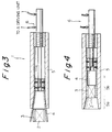
- FIG 3 shows a condition before the drawing operation is carried out by the apparatus 1.
- Each of the grasping members 4 is made of a flexible material, such as a thin stainless steel, and as shown in this figure, the members 4 are formed in such a manner that they can bend radially outward, and thus be spaced from each other. Due to this arrangement, an inside diameter of a space defined by the grasping members 4 when outside the drawing die 5 is greater than an outside diameter of the hollow cylindrical body 3 before forming, and thus the operator is able to fit the hollow cylindrical body 3 into the defined space without difficulty.
- the operator actuates the operating lever 14 of the driving unit 12 (Fig. 2) and the actuator 6 causes the grasping members 4 to be drawn into the drawing die 5. Consequently, the hollow cylindrical body 3 containing the honeycomb member 2 is forced to pass through the tapered part 5a and the following straight part 5b of the drawing die 5, whereby the diameter of the hollow cylindrical body 3 is contracted, and further, the honeycomb member 2 is brought into firm contact with the inside surface of the hollow cylindrical body 3, and accordingly, a catalytic converter having an accurate desired outside diameter is produced, as shown in Fig. 4.
- the finished product i.e., the catalytic converter
- the actuator 6 by operating the actuator 6 in an opposite direction to that of the drawing process, the finished product, i.e., the catalytic converter, is pushed out of the drawing die 5 by the grasping members 4, to a point at which the operator can easily pick up the finished product.
- the honeycomb member 2 and the hollow cylindrical body 3 do not come into direct contact with the drawing die 5 during the drawing process, neither scratches nor baking cracks are produced on the outside surface of the hollow cylindrical body 3, and further, the soldering or welding of each part of the catalytic converter can be carried out under good conditions, i.e., without a usual contamination of the surface thereof by lubricating oil.
- the dimensions after spring-back of the honeycomb members 2 and the outer cylindrical body 3 are taken into account when determining the dimension of the straight part 5b.
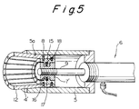
- Figures 5 and 6 show a second embodiment of the present invention, by which a more compact contracting apparatus is provided than that provided in accordance with the above first embodiment.
- the means for connecting the grasping members 4' with the actuator 6 comprises a plurality of supporting members 15, and a column 7' into which the rod 9 of the actuator 6 is screwed and fixed.
- the column 7' is provided with a circumferential groove 16, and each of the supporting members 15 has a substantially T-shaped configuration and is fixed to each grasping member 4' by screws 8.
- a leg part of each support member 15 is provided with an orifice 17 for receiving a compression spring 18 therein.
- each supporting member 15 secured to a grasping member 4' is arranged around the column 7' so that the leg part of the supporting member 15 is engaged in the circumferential groove 16.
- the length of the leg part is shorter than the depth of the groove 16, and thus the compression springs 18 in the orifices 17 are seated on a bottom of the groove 16.
- the grasping members 4' are moved by the actuator 6 in such a manner that the members 4' protrude out of the opening of the drawing die 5, as shown in Fig. 5, and due to the tapered part 5a of the drawing die 5, the top of each the grasping members 4' is displaced radially outward by the action of the compression spring 18, whereby the diameter of the cylindrical space defined by the grasping members 4' is increased, and thus the hollow cylindrical body 3 can be easily inserted into the space defined by the grasping members 4'.
- the operator actuates the operating lever (not shown in Fig. 6) of the driving unit 12 so that the actuator 6 draws the grasping members 4' into the drawing die 5. Consequently, the hollow cylindrical body 3 containing the honeycomb member 2 is forced to pass through the tapered part 5a and into the following straight part 5b, whereby the diameter thereof is contract and the honeycomb member 2 is brought into firm contact with the inner surface of the hollow cylindrical body 3, and thus a catalytic converter having an accurate desired outside diameter is produced, as shown in Fig. 6.
- each grasping member 4' are easily radially displaceable, a more compact apparatus for diametrically contracting the hollow cylindrical body can be provided than that provided in accordance with the first embodiment of the invention in which, due to an outwardly curved configuration thereof, each grasping member must be of a certain length, to be able to form a space large enough to grasp the outer cylindrical body when outsid of the drawing die, as shown in Fig. 3.
- Figure 7 shows a part of an installation for diametrically contracting the hollow cylindrical bodies in sequence, employing the above-mentioned apparatus in accordance with the present invention.
- a turn table 19 is provided on which hollow cylindrical bodies 3 to be diametrically contracted are arranged.
- the turn table 19 is intermittently rotated in the direction shown by an arrow A and the hollow cylindrical body 3 is transferred from a position B to a position C on the turn table 19.
- the honeycomb member 2 is inserted into the hollow cylindrical body 3 and the hollow cylindrical body 3 containing the honeycomb member 2 therein is transferred to a position D, whereat the hollow cylindrical body 3 and the honeycomb member 2 are lifted by a lifting table 20 and pushed into a space defined by the grasping members or 4'.
- the lifting table 20 is moved upward and downward by an actuator 21, such as a hydraulic cylinder, positioned under the turn table 19.
- the hollow cylindrical body 3 containing the honeycomb member 2 is drawn into the drawing die 5 by the grasping members 4, and the hollow cylindrical body 3 and the honeycomb member 2 are diametrically contracted.
- the formed hollow cylindrical body 3 containing the member 2, i.e., the catalytic converter product is pushed out of the drawing die 5 and is returned to the position D on the turn table 19, close to the lifting table 20.
- the catalytic converter is moved to a position E and is then removed from the turn table 19.
- a flat sheet and a corrugated sheet both made of stainless sheet having a thickness of 50 ⁇ m, were prepared and then laminated and wound together to provide honeycomb members having an OD of 101 mm and a length of 100 mm. Then, a brazing material containing a binder was partially coated on peripheral surfaces of the honeycomb members, and the coated honeycomb members were inserted into the hollow cylindrical bodies, respectively.
- the six hollow cylindrical bodies containing the honeycomb member were each placed in an apparatus having twenty grasping members 4' and the actuator of the apparatus activated to draw in and diametrically contract the hollow cylindrical bodies to an outside diameter of 103 mm. Further, the contracted hollow cylindrical bodies were heated to temperature of 1180° c in a vacuum furnace, to braze the honeycomb members to the hollow cylindrical bodies and thereby provide six catalytic converters.
- the inventors produced conventional converters as follows. First, stainless steel plates were bent to a C-shaped cross section by a bending machine, to provide the hollow cylindrical bodies (103 mm OD and 1.5 mm thick before welding). Next, in the same manner as above, honeycomb members (100 mm OD and 100 mm L) were prepared, and each was coated with the brazing material and then inserted into a hollow cylindrical body (not weld: C-shaped cross section), respectively.
- the catalytic converters produced by the present invention were cut open and the joint between the honeycomb member and the outer cylindrical body was inspected. As a result, it was recognized that the honeycomb member was joined to the hollow cylindrical body only at points at which the brazing material had been applied to the outside surface of the honeycomb member, and that since the contact between the flat sheet and the wavy sheet was ensured by the drawing, the brazing of the honeycomb member was also satisfactory.
- a catalytic converter which has highly accurate dimensions after brazing and a heat treatment therefor, and thus there is no need to refinish an outside surface of a hollow cylindrical body of the produced catalytic converter before assembling same into an engine.
- an outside surface 4a of each grasping member 4'' is formed to have an outside surface 4a having the same inclination as an inside surface 5a of the die 5.
- an inside surface 4b of the grasping member 4'' is formed in such a manner that it constitutes a part of a cylindrical surface parallel to an axis X of the apparatus.
- the cylindrical surface is so formed that, when the end surface of the grasping member 4'' is flush with that of the die 5, as shown in Fig. 8, a diameter of the cylindrical surface will be identical to a required outside diameter of the outer cylindrical body 3.
- each member 4'' is moved moved moved radially inward to thus reduce the diameter of the cylindrical surface.
- the members 4 are moved out of the die 5', they are moved radially outward by the springs 18, to thereby increase the diameter of the cylindrical surface.
- the drawing movement of the rod 9 is determined in accordance with a value calculated from the required outside diameter of the cylindrical body 3. Note that, if the outside diameter of the so-formed cylindrical body 3 is larger than the required outside diameter, the drawing movement may be increased, to reduce the outside diameter of the cylindrical body 3.
- a cylindrical body having any desired outside diameter can be produced by an appropriate setting of the drawing movement of the rod 9.
- the length of the drawing die 5' can be reduced, and thus the size of the apparatus can be made smaller than that of the apparatus of the second embodiment.
Landscapes
- Engineering & Computer Science (AREA)
- Chemical & Material Sciences (AREA)
- Mechanical Engineering (AREA)
- Chemical Kinetics & Catalysis (AREA)
- Combustion & Propulsion (AREA)
- General Engineering & Computer Science (AREA)
- Health & Medical Sciences (AREA)
- Toxicology (AREA)
- Exhaust Gas After Treatment (AREA)
- Catalysts (AREA)
Claims (7)
- Verfahren zum diametralen Verengen eines zylindrischen Hohlkörpers, in den mit einem dazwischen befindlichen Spielraum ein wabenartiges Teil insertiert ist, welcher einen Teil eines Katalysators für ein Automobil darstellt, um dadurch den zylindrischen Hohlkörper durch eine diametrale Verengung des zylindrischen Hohlkörpers an das darin befindliche wabenartige Teil eng anzupassen, wobei das Verfahren die Schritte umfaßt:
Greifen des zylindrischen Hohlkörpers an seiner Außenseite mit einer Mehrzahl von verlängerten Greifstäben, die so angeordnet sind, daß sie den zylindrischen Hohlkörper umfassen, wobei ein Ende eines jeden Greifstabs an einer Säule befestigt ist,
Bereitstellen einer zylindrischen Ziehdüse mit einer Öffnung an einem Ende, wobei die Düse über einen spitz zulaufenden Abschnitt in einer ihrer Bohrungen verfügt, in welchem ein Innendurchmesser der Düse entlang ihrer Achse und von der Öffnung hin weg allmählich verengt ist,
Ziehen der Greifstäbe und des zylindrischen Hohlkörpers in die Ziehdüse durch die Öffnung, und
Ausüben einer Druckkraft auf den zylindrischen Hohlkörper mittels Greifstäbe, wenn diese durch die spitz zulaufende innere umfängliche Oberfläche der Ziehdüse gezogen werden, um hierbei den zylindrischen Hohlkörper diametral zu verengen und diesen mit dem darin befindlichen wabenartigen Teil in dichte Anpassung zu bringen. - verfahren nach Anspruch 1, das außerdem die Schritte umfaßt, daß vor dem Ziehen auf eine Innenoberfläche des zylindrischen Hohlkörpers und eine Außenoberfläche des darin befindlichen wabenartigen Teils ein Lötflußmittel aufgetragen wird und der zylindrische Hohlkörper durch eine Wärmebehandlung nach dem Ziehvorgang an das darin befindliche wabenartige Teil gelötet wird.
- Gerät zum diametralen Verengen eines zylindrischen Hohlkörpers (3), in den mit einem dazwischen befindlichen Spielraum ein wabenartiges Teil (2) insertiert ist, welcher einen Teil eines Katalysators für ein Automobil darstellt, um den zylindrischen Hohlkörper (3) durch eine diametrale Verengung des zylindrischen Hohlkörpers (3) an das darin befindliche wabenartige Teil (2) dicht anzupassen, das umfaßt:
eine zylindrischen Ziehdüse (5) mit einer Öffnung an einem Ende, wobei die Düse über einen spitz zulaufenden Abschnitt (5a) in einer ihrer Bohrungen verfügt, in welchem ein Innendurchmesser der Düse (5) entlang ihrer Achse und von der Öffnung hin weg allmählich verengt ist,
eine Mehrzahl von Stäben (4) zum Greifen des zylindrischen Hohlkörpers (3) an dessen Außenseite, wobei die Greifstäbe (4) umfänglich um eine Säule (7) angeordnet sind, die in der Bohrung der Ziehdüse (5) in einer solchen Weise angebracht ist, daß die Greifstäbe (4) axial durch die Öffnung in und aus der Bohrung der Ziehdüse (4) bewegt werden können,
ein Stellglied (6), das an der entgegengesetzten Seite der Öffnung angeordnet ist, wobei das Stellglied (6) einen beweglichen Stab (9) aufweist, der sich in der Bohrung axial erstreckt, wobei der Stab (9) an die Säule (7) gebunden ist, wodurch die Greifstäbe (4) durch das Stellglied (6) beim Verengen des zylindrischen Hohlkörpers (3) in der Bohrung bewegt werden können; und
wobei die Greifstäbe (4) in Übereinstimmung mit einer Verjüngung des spitz zulaufenden Abschnitts (5a) der Ziehdüse (5) verschiebbar sind, wodurch der durch die Greifstäbe (4) gehaltene zylindrische Körper (3) gezwungen wird, durch den spitz zulaufenden Abschnitt (5a) der Ziehdüse (5) durchzupassieren, wenn das Stellglied (6) die Greifstäbe (4) in die Ziehdüse (5) zieht, um dadurch den Durchmesser des zylindrischen Hohlkörpers (3) zu verengen. - Gerät nach Anspruch 3, worin die Ziehdüse (5) mit einem geraden Abschnitt (5b) versehen ist, der nach dem spitz zulaufenden Abschnitt (5a) angeordnet ist und der über einen Durchmesser verfügt, so daß ein Innendurchmesser eines durch die Greifstäbe (4) definierten Raums am geraden Abschnitt (5b) im wesentlichen der gleiche wie der eines fertigen Durchmessers eines zylindrischen Hohlkörpers (3) ist.
- Gerät nach Anspruch 4, worin die Greifstäbe (4) aus rostfreiem Stahl hergestellt sind.
- Gerät nach Anspruch 3, worin zwischen den Greifstäben (4) und der Säule (7) Sprungfedern (18) angeordnet sind, so daß die Greifstäbe (4) durch die Aktion der Sprungfedern (19) radial nach außen hin verschoben werden, wenn die Greifstäbe (4) außerhalb der Ziehdüse (5) durch das Stellglied (6) bewegt werden.
- Gerät nach Anspruch 6, worin jede Außenoberfläche der Greifstäbe (4) so geformt ist, daß sie in Bezug auf, jede Außenoberfläche geneigt ist, damit der fertige Durchmesser des zylindrischen Hohlkörpers (3) im wesentlichen der gleiche wie derjenige eines Raums ist, der durch jede Innenoberfläche der Greifstäbe (4) definiert ist, unter einer Bedingung, bei der die Außenoberfläche mit dem spitz zulaufenden Abschnitt der Ziehdüse (5) in Kontakt kommt.
Priority Applications (1)
| Application Number | Priority Date | Filing Date | Title |
|---|---|---|---|
| DE1990615637 DE69015637T2 (de) | 1990-10-09 | 1990-10-09 | Verfahren und Gerät zum Verengen eines zylindrischen Körpers. |
Applications Claiming Priority (1)
| Application Number | Priority Date | Filing Date | Title |
|---|---|---|---|
| US07/599,356 US5096111A (en) | 1990-10-05 | 1990-10-05 | Method for contracting a cylindrical body |
Publications (2)
| Publication Number | Publication Date |
|---|---|
| EP0480082A1 EP0480082A1 (de) | 1992-04-15 |
| EP0480082B1 true EP0480082B1 (de) | 1994-12-28 |
Family
ID=24399292
Family Applications (1)
| Application Number | Title | Priority Date | Filing Date |
|---|---|---|---|
| EP90119335A Expired - Lifetime EP0480082B1 (de) | 1990-10-05 | 1990-10-09 | Verfahren und Gerät zum Verengen eines zylindrischen Körpers |
Country Status (2)
| Country | Link |
|---|---|
| US (1) | US5096111A (de) |
| EP (1) | EP0480082B1 (de) |
Cited By (1)
| Publication number | Priority date | Publication date | Assignee | Title |
|---|---|---|---|---|
| US8832937B2 (en) | 2011-10-11 | 2014-09-16 | Benteler Automobiltechnik Gmbh | Method for stuffing a monolith with a mounting mat into a housing |
Families Citing this family (28)
| Publication number | Priority date | Publication date | Assignee | Title |
|---|---|---|---|---|
| TW225491B (de) * | 1992-05-29 | 1994-06-21 | Nippon Yakin Kogyo Co Ltd | |
| DE4241469A1 (de) * | 1992-12-09 | 1994-06-16 | Emitec Emissionstechnologie | Katalytischer Konverter mit zwei oder mehr Wabenkörpern in einem Mantelrohr und Verfahren zu seiner Herstellung |
| JPH0842333A (ja) * | 1994-06-06 | 1996-02-13 | Ford Motor Co | 触媒排気処理装置の製造方法 |
| DE19509029C2 (de) * | 1994-06-06 | 1999-11-11 | Ford Werke Ag | Verfahren zur Herstellung einer katalytischen Behandlungsvorrichtung |
| DE19549603C2 (de) * | 1994-06-06 | 2003-10-23 | Ford Werke Ag | Vorrichtung zur katalytischen Behandlung von Abgasen und Verfahren zu ihrer Herstellung |
| DE4439685A1 (de) * | 1994-11-07 | 1996-05-09 | Emitec Emissionstechnologie | Verfahren und Vorrichtung zur Herstellung eines Wabenkörpers, insbesondere Katalysator-Trägerkörpers, mit Gehäuse |
| US5960529A (en) * | 1994-11-07 | 1999-10-05 | Emitec Gessellschaft Fuer Emissionstechnologie Mbh | Apparatus and method for deforming a jacket tube of a honeycomb body |
| US6029488A (en) * | 1995-06-20 | 2000-02-29 | Emitec Gesellschaft Fuer Emissionstechnologie Mbh | Apparatus and process for producing a honeycomb body from intertwined sheet metal layers |
| US5626604A (en) * | 1995-12-05 | 1997-05-06 | Cordis Corporation | Hand held stent crimping device |
| DE69716535T2 (de) * | 1996-08-14 | 2003-02-27 | Denso Corp., Kariya | Keramischer katalytischer Konverter |
| US5836952A (en) * | 1996-08-21 | 1998-11-17 | Cordis Corporation | Hand-held stent crimper |
| US5675858A (en) * | 1996-09-12 | 1997-10-14 | Von Meyer; Robert | String mop with wringer |
| US6101714A (en) * | 1997-09-08 | 2000-08-15 | Corning Incorporated | Method of making a catalytic converter for use in an internal combustion engine |
| US5909916A (en) * | 1997-09-17 | 1999-06-08 | General Motors Corporation | Method of making a catalytic converter |
| US6405437B1 (en) | 1997-09-17 | 2002-06-18 | Arvinmeritor, Inc. | Apparatus and method for encasing an object in a case |
| US5980837A (en) * | 1997-12-03 | 1999-11-09 | Ford Global Technologies, Inc. | Exhaust treatment device for automotive vehicle having one-piece housing with integral inlet and outlet gas shield diffusers |
| WO1999064732A1 (en) * | 1998-06-09 | 1999-12-16 | Asec Manufacturing Partnership | Exhaust pipe catalytic device |
| US6591497B2 (en) * | 1998-08-27 | 2003-07-15 | Delphi Technologies, Inc. | Method of making converter housing size based upon substrate size |
| US6450002B1 (en) * | 2000-12-05 | 2002-09-17 | Robert S. Smith | Compact apparatus for grooving a tube and method for grooving a tube |
| US7047641B2 (en) | 2002-01-31 | 2006-05-23 | Delphi Technologies, Inc. | Exhaust emission control device manufacturing method |
| JP4459962B2 (ja) * | 2003-05-13 | 2010-04-28 | ヘス エンジニアリング インク | 触媒コンバータを製造する方法及び装置 |
| DE102005002165A1 (de) * | 2005-01-17 | 2006-07-27 | Arvinmeritor Emissions Technologies Gmbh | Verfahren zur Herstellung einer abgasführenden Vorrichtung |
| RU2404848C2 (ru) * | 2005-04-14 | 2010-11-27 | Кэтасел Корп. | Способ введения реакторного картриджа в длинную трубу и способ удаления реакторного картриджа из указанной трубы |
| US7565743B2 (en) * | 2005-04-14 | 2009-07-28 | Catacel Corp. | Method for insertion and removal of a catalytic reactor cartridge |
| US7472936B2 (en) * | 2005-04-14 | 2009-01-06 | Catacel Corp. | Tool for insertion and removal of a catalytic reactor cartridge |
| US20060230613A1 (en) * | 2005-04-14 | 2006-10-19 | Catacel Corporation | Catalytic reactor cartridge |
| WO2006113196A2 (en) * | 2005-04-14 | 2006-10-26 | Catacel Corp. | Catalytic reactor cartridge |
| US8307753B2 (en) * | 2006-08-11 | 2012-11-13 | Techno-Sciences, Inc. | Fluidic artificial muscle actuator and swaging process therefor |
Family Cites Families (17)
| Publication number | Priority date | Publication date | Assignee | Title |
|---|---|---|---|---|
| US579214A (en) * | 1897-03-23 | Machine for swaging or tapering pipes or flues | ||
| US2998049A (en) * | 1958-01-28 | 1961-08-29 | Goodyear Tire & Rubber | Apparatus for building air spring |
| US3085316A (en) * | 1959-03-26 | 1963-04-16 | Sage Electronics Corp | Method of making a resistor |
| US3208131A (en) * | 1961-03-22 | 1965-09-28 | Universal Oil Prod Co | Rigid catalytic metallic unit and method for the production thereof |
| US3182387A (en) * | 1962-08-13 | 1965-05-11 | Tennant Co G H | Filter fabricating apparatus |
| FR1590802A (de) * | 1968-11-05 | 1970-04-20 | ||
| US4093423A (en) * | 1972-10-03 | 1978-06-06 | Volkswagenwerk Aktiengesellschaft | Catalytic device for the catalytic purification of exhaust gases |
| US3977065A (en) * | 1973-03-01 | 1976-08-31 | Wyle Laboratories | Crimping machine |
| FR2303622A1 (fr) * | 1975-03-10 | 1976-10-08 | Microturbo Sa | Procede de fabrication d'une unite du type echangeur de chaleur |
| GB1551917A (en) * | 1976-11-16 | 1979-09-05 | British Leyland Uk Ltd | Method of and apparatus for fabricating a catalytic reactor |
| GB2020190A (en) * | 1978-05-04 | 1979-11-14 | Ti Silencers Ltd | Constructing a catalyst assembly |
| DE2856030C2 (de) * | 1978-12-23 | 1987-02-12 | Süddeutsche Kühlerfabrik Julius Fr. Behr GmbH & Co KG, 7000 Stuttgart | Verfahren zum Herstellen einer aus Metallfolien gewickelten Trägermatrix für eine Abgaspatrone |
| DE2924592C2 (de) * | 1979-06-19 | 1983-05-26 | Süddeutsche Kühlerfabrik Julius Fr. Behr GmbH & Co KG, 7000 Stuttgart | Verfahren zum Herstellen einer Trägermatrix für einen katalytischen Reaktor zur Abgasreinigung bei Brennkraftmaschinen von Kraftfahrzeugen |
| US4300956A (en) * | 1980-04-14 | 1981-11-17 | Matthey Bishop, Inc. | Method of preparing a metal substrate for use in a catalytic converter |
| DE3331721C2 (de) * | 1983-09-02 | 1986-06-05 | Peter 6000 Frankfurt Schröck | Radialpresse für Werkstücke mit zylindrischer Außenfläche |
| US4667386A (en) * | 1985-08-23 | 1987-05-26 | Honda Giken Kogyo Kabushiki Kaisha | Method and apparatus for assembling an insert assembly for a catalytic converter |
| DE3532408A1 (de) * | 1985-09-11 | 1987-03-19 | Sueddeutsche Kuehler Behr | Traegermatrix, insbesondere fuer einen katalytischen reaktor zur abgasreinigung bei brennkraftmaschinen |
-
1990
- 1990-10-05 US US07/599,356 patent/US5096111A/en not_active Expired - Lifetime
- 1990-10-09 EP EP90119335A patent/EP0480082B1/de not_active Expired - Lifetime
Cited By (2)
| Publication number | Priority date | Publication date | Assignee | Title |
|---|---|---|---|---|
| US8832937B2 (en) | 2011-10-11 | 2014-09-16 | Benteler Automobiltechnik Gmbh | Method for stuffing a monolith with a mounting mat into a housing |
| DE102011115509C5 (de) * | 2011-10-11 | 2020-01-16 | Benteler Automobiltechnik Gmbh | Verfahren zum Einhausen eines Monolithen mit Lagerungsmatte in ein Gehäuse durch Stopfen |
Also Published As
| Publication number | Publication date |
|---|---|
| US5096111A (en) | 1992-03-17 |
| EP0480082A1 (de) | 1992-04-15 |
Similar Documents
| Publication | Publication Date | Title |
|---|---|---|
| EP0480082B1 (de) | Verfahren und Gerät zum Verengen eines zylindrischen Körpers | |
| US3766631A (en) | Method of interconnecting a tube to a plate | |
| US5890287A (en) | Connection structure and process for connecting eye joints and slender metal pipes | |
| US5549335A (en) | Solderless metallurgical joint | |
| US4400860A (en) | Method for producing a cartridge for purifying exhaust gas | |
| US5251714A (en) | Method for soldering pipe end and counter member | |
| EP0609449B1 (de) | Methode zur herstellung eines metallischen, wabenförmigen trägers | |
| EP0921892B1 (de) | Linear-reibschweissverfahren zum herstellen von radfelgen | |
| US8857056B2 (en) | Method of manufacturing an exhaust gas carrying device and tool therefor | |
| JPH0118298B2 (de) | ||
| JPH08226584A (ja) | 可撓性金属ホースコネクタ及びその形成方法 | |
| JPH10280953A (ja) | 消音器とその製造方法 | |
| US5011064A (en) | Method of manufacturing a double-walled tube | |
| US7530252B2 (en) | Method and apparatus for working tube | |
| JPH10511444A (ja) | 組立カム軸の製造方法及びこの方法を実施するための工具 | |
| US20220203422A1 (en) | Multi-axis roll-forming of stepped-diameter cylinder | |
| US20070051156A1 (en) | Manufacturing method for an annular member and a pronged annular member | |
| KR920011052B1 (ko) | 주름파이프의 제조장치 | |
| JP2829027B2 (ja) | 自動車触媒用金属担体の製造方法 | |
| JPH0647284A (ja) | メタル担体の製造方法 | |
| JPS637900B2 (de) | ||
| JPS61159238A (ja) | 熱交換器の円筒形の集合管構造を形成するリング板状の構成部材を製作する方法及び装置 | |
| JPH05131148A (ja) | 楕円型メタル担体の製造方法 | |
| JPH05337573A (ja) | 管部品の接合方法及びこの接合方法を用いた連結管体 | |
| JP3302116B2 (ja) | メタル担体の製造方法 |
Legal Events
| Date | Code | Title | Description |
|---|---|---|---|
| PUAI | Public reference made under article 153(3) epc to a published international application that has entered the european phase |
Free format text: ORIGINAL CODE: 0009012 |
|
| 17P | Request for examination filed |
Effective date: 19901220 |
|
| AK | Designated contracting states |
Kind code of ref document: A1 Designated state(s): DE GB |
|
| 17Q | First examination report despatched |
Effective date: 19930723 |
|
| GRAA | (expected) grant |
Free format text: ORIGINAL CODE: 0009210 |
|
| AK | Designated contracting states |
Kind code of ref document: B1 Designated state(s): DE GB |
|
| REF | Corresponds to: |
Ref document number: 69015637 Country of ref document: DE Date of ref document: 19950209 |
|
| PLBE | No opposition filed within time limit |
Free format text: ORIGINAL CODE: 0009261 |
|
| STAA | Information on the status of an ep patent application or granted ep patent |
Free format text: STATUS: NO OPPOSITION FILED WITHIN TIME LIMIT |
|
| 26N | No opposition filed | ||
| REG | Reference to a national code |
Ref country code: GB Ref legal event code: IF02 |
|
| PGFP | Annual fee paid to national office [announced via postgrant information from national office to epo] |
Ref country code: GB Payment date: 20031008 Year of fee payment: 14 |
|
| PG25 | Lapsed in a contracting state [announced via postgrant information from national office to epo] |
Ref country code: GB Free format text: LAPSE BECAUSE OF NON-PAYMENT OF DUE FEES Effective date: 20041009 |
|
| GBPC | Gb: european patent ceased through non-payment of renewal fee |
Effective date: 20041009 |
|
| PGFP | Annual fee paid to national office [announced via postgrant information from national office to epo] |
Ref country code: DE Payment date: 20091001 Year of fee payment: 20 |
|
| PG25 | Lapsed in a contracting state [announced via postgrant information from national office to epo] |
Ref country code: DE Free format text: LAPSE BECAUSE OF EXPIRATION OF PROTECTION Effective date: 20101009 |