EP0480088A1 - Dispositif pour la distribution de carburants liquides - Google Patents
Dispositif pour la distribution de carburants liquides Download PDFInfo
- Publication number
- EP0480088A1 EP0480088A1 EP90119455A EP90119455A EP0480088A1 EP 0480088 A1 EP0480088 A1 EP 0480088A1 EP 90119455 A EP90119455 A EP 90119455A EP 90119455 A EP90119455 A EP 90119455A EP 0480088 A1 EP0480088 A1 EP 0480088A1
- Authority
- EP
- European Patent Office
- Prior art keywords
- fuel
- gas
- pump
- hydraulic motor
- storage tank
- Prior art date
- Legal status (The legal status is an assumption and is not a legal conclusion. Google has not performed a legal analysis and makes no representation as to the accuracy of the status listed.)
- Granted
Links
- 239000000446 fuel Substances 0.000 title claims abstract description 60
- 239000007788 liquid Substances 0.000 title claims abstract description 10
- 238000007789 sealing Methods 0.000 claims description 3
- 238000010276 construction Methods 0.000 abstract 1
- 239000000945 filler Substances 0.000 abstract 1
- 230000001413 cellular effect Effects 0.000 description 5
- 239000002828 fuel tank Substances 0.000 description 3
- 238000009434 installation Methods 0.000 description 3
- 230000005540 biological transmission Effects 0.000 description 2
- 238000012423 maintenance Methods 0.000 description 2
- 230000008439 repair process Effects 0.000 description 2
- 239000000470 constituent Substances 0.000 description 1
- 238000000605 extraction Methods 0.000 description 1
- 238000009420 retrofitting Methods 0.000 description 1
- 238000005096 rolling process Methods 0.000 description 1
Images

Classifications
-
- B—PERFORMING OPERATIONS; TRANSPORTING
- B67—OPENING, CLOSING OR CLEANING BOTTLES, JARS OR SIMILAR CONTAINERS; LIQUID HANDLING
- B67D—DISPENSING, DELIVERING OR TRANSFERRING LIQUIDS, NOT OTHERWISE PROVIDED FOR
- B67D7/00—Apparatus or devices for transferring liquids from bulk storage containers or reservoirs into vehicles or into portable containers, e.g. for retail sale purposes
- B67D7/04—Apparatus or devices for transferring liquids from bulk storage containers or reservoirs into vehicles or into portable containers, e.g. for retail sale purposes for transferring fuels, lubricants or mixed fuels and lubricants
- B67D7/0476—Vapour recovery systems
- B67D7/0478—Vapour recovery systems constructional features or components
- B67D7/048—Vapour flow control means, e.g. valves, pumps
- B67D7/0482—Vapour flow control means, e.g. valves, pumps using pumps driven at different flow rates
-
- B—PERFORMING OPERATIONS; TRANSPORTING
- B67—OPENING, CLOSING OR CLEANING BOTTLES, JARS OR SIMILAR CONTAINERS; LIQUID HANDLING
- B67D—DISPENSING, DELIVERING OR TRANSFERRING LIQUIDS, NOT OTHERWISE PROVIDED FOR
- B67D7/00—Apparatus or devices for transferring liquids from bulk storage containers or reservoirs into vehicles or into portable containers, e.g. for retail sale purposes
- B67D7/06—Details or accessories
- B67D7/84—Casings, cabinets or frameworks; Trolleys or like movable supports
Definitions
- the invention relates to a device for dispensing liquid fuels from a storage tank by means of a nozzle provided with a fuel nozzle and gas nozzle, to which the fuel is supplied by a fuel pump arranged in the lower part of a fuel pump with the interposition of a measuring unit with a pulse generator for determining the amount of fuel flowing through, and which Extraction of the gas escaping during fuel delivery is provided with a gas recirculation channel which is connected to a gas line opening into the storage tank, in which a gas pump is arranged which can be driven by a hydraulic motor which in turn is driven by the fuel delivered by the fuel pump.
- Such devices for dispensing liquid fuels from a storage tank are known from DE-PS 36 13 453.
- this known device is used as a hydraulic motor, e.g. drives the gas pump via a gear transmission, uses the measuring unit, which in turn is driven by the fuel delivered by the fuel pump in the manner of a liquid motor. This ensures that the amount of gas extracted is proportional to the amount of fuel dispensed.
- the invention has for its object to develop a device for dispensing liquid fuels of the type described in such a way that with little technical effort and without intervention in the sealed parts of the pump, existing pumps can be easily retrofitted.
- the solution to this problem by the invention is characterized in that the hydraulic motor and the gas pump are formed as vane units in a common housing and with a common shaft and between the fuel pump and the measuring unit outside the verifiable and sealed parts of the fuel pump, which essentially consist of the measuring unit , the pulse generator, a calculator and display devices for the amount and price of the fuel dispensed are arranged.
- both the hydraulic motor and the gas pump as vane units in a common housing and with a common shaft results in a compact unit that can be retrofitted even in the limited space of existing dispensers. Since the installation of the hydraulic motor takes place according to the invention between the fuel pump and the measuring unit, no parts of the gas pump that are subject to calibration and lead sealing are touched, so that re-calibration of the gas pump is not necessary either in the case of subsequent installation or in later maintenance and repair work.
- the speed of the common shaft of the hydraulic motor and gas pump can be monitored for the purpose of comparison with the pulses received by the computer of the pulse generator driven by the measuring unit.
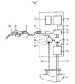
- the device shown in Fig. 1 is used to dispense liquid fuels from a storage tank 1, which is normally underground.
- the fuel in this storage tank 1 is drawn in via a fuel line by means of a fuel pump 3, which is arranged together with a gas separator in a so-called monoblock in the lower part of a fuel dispenser 4.
- the fuel drawn in by the fuel pump 3 from the storage tank 1 is fed to a measuring unit 5, which is usually designed as a piston knife and is provided with a pulse generator 6.
- This pulse generator 6 generates a number of pulses corresponding to the flow rate determined by the measuring unit 5, which are forwarded via a pulse line 7 to a computer 8 which determines the output quantity determined by the measuring unit 5 and the associated price of the fuel, and display devices 9 Display of delivery quantity and associated price controls.
- the fuel emerging from the measuring unit 5 passes through an adapter 10 into a fuel nozzle 11, at the end of which a fuel nozzle 12 with a gas suction nozzle 12a is arranged for filling the respective fuel tank.
- the device In order to prevent the fuel containing volatile constituents from being released and the gas displaced by the liquid when filling the fuel tank from escaping into the atmosphere, the device is provided with a gas recirculation into the storage tank 1.
- This gas return comprises a gas return duct 13 running in the dispensing hose 11, which is preferably formed by the dispensing hose 11 consisting of two coaxial running hoses, one medium, for example the fuel, flowing in the outer hose and the inner hose being designed as a gas return duct 13.
- a gas line 14 is connected to this return duct 13, which leads into the storage tank 1.
- a gas pump 15 is arranged in the gas line 14, which is driven by a hydraulic motor 16, which in turn is in the fuel line 2 is arranged between the fuel pump 3 and the measuring unit 5.
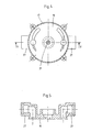
- the gas pump 15 and the hydraulic motor 16 are designed as vane cell units which are arranged in a common housing 17.
- This cylindrical housing 17 is closed at the end by a housing cover 18, which is sealed off from the housing 17 by means of seals 19.
- a shaft 21 is mounted in the housing covers 18 via roller bearings 20, on which two cellular wheels 22 are fastened by means of a wedge 23.
- Pallets 24 are slidably guided in radial slots of these cellular wheels 22. These pallets 24 interact with an eccentric bore of an intermediate housing 25 surrounding the respective cellular wheel 22.
- the connection piece 27 for the inflow and outflow of both the gas pump 15 and the hydraulic motor 16 are - as is apparent in particular from FIG. 5 - formed in the respective housing cover 18.
- the vane cell unit shown in FIGS. 2 to 5, which forms the gas pump 15 and the hydraulic motor 16 driving this gas pump 15, is installed as a compact unit in the fuel line 2 between the fuel pump 3 and the measuring unit 5, as is shown in the schematic representation of FIG. 1 can be seen.
- the gas pump 15 and the hydraulic motor 16 are shown as individual units for better understanding.
- the gas line 14 is connected to the gas pump 15 with the installation of a flame arrester 28.
Landscapes
- Engineering & Computer Science (AREA)
- Mechanical Engineering (AREA)
- Physics & Mathematics (AREA)
- Fluid Mechanics (AREA)
- Loading And Unloading Of Fuel Tanks Or Ships (AREA)
- Feeding And Controlling Fuel (AREA)
- Measuring Volume Flow (AREA)
Priority Applications (4)
| Application Number | Priority Date | Filing Date | Title |
|---|---|---|---|
| EP90119455A EP0480088B1 (fr) | 1990-10-11 | 1990-10-11 | Dispositif pour la distribution de carburants liquides |
| ES199090119455T ES2041098T3 (es) | 1990-10-11 | 1990-10-11 | Dispositivo para el suministro de carburantes liquidos. |
| DE9090119455T DE59001573D1 (de) | 1990-10-11 | 1990-10-11 | Vorrichtung zur ausgabe fluessiger kraftstoffe. |
| AT90119455T ATE89810T1 (de) | 1990-10-11 | 1990-10-11 | Vorrichtung zur ausgabe fluessiger kraftstoffe. |
Applications Claiming Priority (1)
| Application Number | Priority Date | Filing Date | Title |
|---|---|---|---|
| EP90119455A EP0480088B1 (fr) | 1990-10-11 | 1990-10-11 | Dispositif pour la distribution de carburants liquides |
Publications (2)
| Publication Number | Publication Date |
|---|---|
| EP0480088A1 true EP0480088A1 (fr) | 1992-04-15 |
| EP0480088B1 EP0480088B1 (fr) | 1993-05-26 |
Family
ID=8204600
Family Applications (1)
| Application Number | Title | Priority Date | Filing Date |
|---|---|---|---|
| EP90119455A Expired - Lifetime EP0480088B1 (fr) | 1990-10-11 | 1990-10-11 | Dispositif pour la distribution de carburants liquides |
Country Status (4)
| Country | Link |
|---|---|
| EP (1) | EP0480088B1 (fr) |
| AT (1) | ATE89810T1 (fr) |
| DE (1) | DE59001573D1 (fr) |
| ES (1) | ES2041098T3 (fr) |
Cited By (7)
| Publication number | Priority date | Publication date | Assignee | Title |
|---|---|---|---|---|
| WO1995030564A1 (fr) * | 1994-05-07 | 1995-11-16 | Rhein-Ruhr Maschinenbau Gmbh Dura Sandstrahltechnik | Station-service modulaire |
| WO1998017580A1 (fr) * | 1996-10-18 | 1998-04-30 | Delaware Capital Formation, Inc. | Distributeur d'essence a pompe interne integree et auto-alimentee destinee a recuperer la vapeur d'essence |
| US7584644B2 (en) * | 2004-04-13 | 2009-09-08 | Guy Lamontagne | Calibrator for fuel pump |
| CN100588469C (zh) * | 2006-07-31 | 2010-02-10 | 伊利诺斯器械工程公司 | 通过具有通用连接器的较短软管互相连接的远程计量台和喷头 |
| CN112301230A (zh) * | 2020-09-04 | 2021-02-02 | 武汉科技大学 | 一种空心电渣重熔自耗电极及其制备方法和电渣重熔方法 |
| CN112729483A (zh) * | 2020-12-21 | 2021-04-30 | 赣州久创科技有限公司 | 一种加油机自动检定装置用的储油箱体 |
| CN112729482A (zh) * | 2020-12-21 | 2021-04-30 | 赣州久创科技有限公司 | 一种加油机用自动检定系统 |
Citations (2)
| Publication number | Priority date | Publication date | Assignee | Title |
|---|---|---|---|---|
| GB1551714A (en) * | 1978-03-07 | 1979-08-30 | Texaco Development Corp | Closed fuel system with vacuum assist |
| DE3613453A1 (de) * | 1986-04-21 | 1987-10-22 | Deutsche Geraetebau Gmbh | Vorrichtung zum betanken von kraftfahrzeugen |
-
1990
- 1990-10-11 AT AT90119455T patent/ATE89810T1/de not_active IP Right Cessation
- 1990-10-11 ES ES199090119455T patent/ES2041098T3/es not_active Expired - Lifetime
- 1990-10-11 DE DE9090119455T patent/DE59001573D1/de not_active Expired - Fee Related
- 1990-10-11 EP EP90119455A patent/EP0480088B1/fr not_active Expired - Lifetime
Patent Citations (2)
| Publication number | Priority date | Publication date | Assignee | Title |
|---|---|---|---|---|
| GB1551714A (en) * | 1978-03-07 | 1979-08-30 | Texaco Development Corp | Closed fuel system with vacuum assist |
| DE3613453A1 (de) * | 1986-04-21 | 1987-10-22 | Deutsche Geraetebau Gmbh | Vorrichtung zum betanken von kraftfahrzeugen |
Cited By (9)
| Publication number | Priority date | Publication date | Assignee | Title |
|---|---|---|---|---|
| WO1995030564A1 (fr) * | 1994-05-07 | 1995-11-16 | Rhein-Ruhr Maschinenbau Gmbh Dura Sandstrahltechnik | Station-service modulaire |
| WO1998017580A1 (fr) * | 1996-10-18 | 1998-04-30 | Delaware Capital Formation, Inc. | Distributeur d'essence a pompe interne integree et auto-alimentee destinee a recuperer la vapeur d'essence |
| US5850856A (en) * | 1996-10-18 | 1998-12-22 | Delaware Capital Formation, Inc. | Gasoline dispenser with integral, internal self powered vapor recovery pump |
| US7584644B2 (en) * | 2004-04-13 | 2009-09-08 | Guy Lamontagne | Calibrator for fuel pump |
| CN100588469C (zh) * | 2006-07-31 | 2010-02-10 | 伊利诺斯器械工程公司 | 通过具有通用连接器的较短软管互相连接的远程计量台和喷头 |
| CN112301230A (zh) * | 2020-09-04 | 2021-02-02 | 武汉科技大学 | 一种空心电渣重熔自耗电极及其制备方法和电渣重熔方法 |
| CN112301230B (zh) * | 2020-09-04 | 2022-07-29 | 武汉科技大学 | 一种空心电渣重熔自耗电极及其制备方法和电渣重熔方法 |
| CN112729483A (zh) * | 2020-12-21 | 2021-04-30 | 赣州久创科技有限公司 | 一种加油机自动检定装置用的储油箱体 |
| CN112729482A (zh) * | 2020-12-21 | 2021-04-30 | 赣州久创科技有限公司 | 一种加油机用自动检定系统 |
Also Published As
| Publication number | Publication date |
|---|---|
| EP0480088B1 (fr) | 1993-05-26 |
| ATE89810T1 (de) | 1993-06-15 |
| ES2041098T3 (es) | 1993-11-01 |
| DE59001573D1 (de) | 1993-07-01 |
Similar Documents
| Publication | Publication Date | Title |
|---|---|---|
| DE69602213T2 (de) | Abgabegerät für mehrere Kraftstoffe mit einem gemeinsamen Durchflussmesser | |
| DE3916021A1 (de) | Spraydose | |
| DE19652120A1 (de) | Benzindampfrückgewinnungsvorrichtung und -verfahren | |
| DE8717378U1 (de) | Zapfsäule für den Einbau in Kraftfahrzeugtankstellen mit Dampfabsaugung durch eine Gasförderpumpe | |
| DE69100299T2 (de) | Dampfrückgewinnungsvorrichtung an einem Ausgabegerät für niedrig siedende Flüssigkeiten. | |
| EP0480088B1 (fr) | Dispositif pour la distribution de carburants liquides | |
| DE3038334C2 (fr) | ||
| EP0895960B1 (fr) | Procédé et dispositif de distribution de liquide à partir d'un véhicule citerne comportant plusieurs compartiments de stockage | |
| DE3903603A1 (de) | Tankanlage fuer kraftfahrzeuge | |
| DE3916691C2 (de) | Zapfpistole zum Betanken von Kraftfahrzeugen mit Treibstoff | |
| DE69724431T2 (de) | Befüllvorrichtung | |
| DE3228265C2 (fr) | ||
| EP3757060B1 (fr) | Installation de distribution du liquide d'un véhicule citerne contenant plusieurs chambres | |
| EP0870728B1 (fr) | Dispositif de distribution de carburant liquide | |
| EP0070555B1 (fr) | Installation pour ravitailler des véhicules, particulièrement en carburants cryogéniques liquides | |
| DE2353916C2 (de) | Vorrichtung zum Fördern und gleichzeitigen Volumenmessen von Chargen von Flüssigkeiten | |
| DE2037842B2 (de) | Vorrichtung zur Abgabe einer fest vorgegebenen Flüssigkeitsmenge | |
| DE4403663C1 (de) | Kraftstoffgemisch-Ausgabevorrichtung | |
| EP0915054B1 (fr) | Dispositif de distribution de différents types de carburants à une pompe unique et méthode pour déterminer le prix adaptée à un tel dispositif | |
| DE2807244C2 (fr) | ||
| EP0705789B1 (fr) | Pompe de refoulement de vapeurs | |
| EP0678476A1 (fr) | Dispositif pour la distribution des carburants liquides | |
| DE2840157A1 (de) | Vorrichtung zur abgabe fluessiger kraftstoffe | |
| DE9002828U1 (de) | Zapfsäule zum Einbau in Kraftfahrzeugtankstellen für die Abgabe von Kraftstoff und von Kraftstoff-Öl-Gemisch | |
| DE2650239A1 (de) | Kraftstoffzapfanlage |
Legal Events
| Date | Code | Title | Description |
|---|---|---|---|
| PUAI | Public reference made under article 153(3) epc to a published international application that has entered the european phase |
Free format text: ORIGINAL CODE: 0009012 |
|
| 17P | Request for examination filed |
Effective date: 19910725 |
|
| AK | Designated contracting states |
Kind code of ref document: A1 Designated state(s): AT BE CH DE ES FR GR IT LI LU NL |
|
| 17Q | First examination report despatched |
Effective date: 19921106 |
|
| GRAA | (expected) grant |
Free format text: ORIGINAL CODE: 0009210 |
|
| AK | Designated contracting states |
Kind code of ref document: B1 Designated state(s): AT BE CH DE ES FR GR IT LI LU NL |
|
| REF | Corresponds to: |
Ref document number: 89810 Country of ref document: AT Date of ref document: 19930615 Kind code of ref document: T |
|
| ITF | It: translation for a ep patent filed | ||
| REF | Corresponds to: |
Ref document number: 59001573 Country of ref document: DE Date of ref document: 19930701 |
|
| ET | Fr: translation filed | ||
| REG | Reference to a national code |
Ref country code: GR Ref legal event code: FG4A Free format text: 3008443 |
|
| REG | Reference to a national code |
Ref country code: ES Ref legal event code: FG2A Ref document number: 2041098 Country of ref document: ES Kind code of ref document: T3 |
|
| EPTA | Lu: last paid annual fee | ||
| PLBE | No opposition filed within time limit |
Free format text: ORIGINAL CODE: 0009261 |
|
| STAA | Information on the status of an ep patent application or granted ep patent |
Free format text: STATUS: NO OPPOSITION FILED WITHIN TIME LIMIT |
|
| 26N | No opposition filed | ||
| PGFP | Annual fee paid to national office [announced via postgrant information from national office to epo] |
Ref country code: FR Payment date: 19950918 Year of fee payment: 6 |
|
| PGFP | Annual fee paid to national office [announced via postgrant information from national office to epo] |
Ref country code: LU Payment date: 19951001 Year of fee payment: 6 |
|
| PGFP | Annual fee paid to national office [announced via postgrant information from national office to epo] |
Ref country code: NL Payment date: 19951020 Year of fee payment: 6 Ref country code: AT Payment date: 19951020 Year of fee payment: 6 |
|
| PGFP | Annual fee paid to national office [announced via postgrant information from national office to epo] |
Ref country code: ES Payment date: 19951023 Year of fee payment: 6 Ref country code: CH Payment date: 19951023 Year of fee payment: 6 |
|
| PGFP | Annual fee paid to national office [announced via postgrant information from national office to epo] |
Ref country code: GR Payment date: 19951030 Year of fee payment: 6 |
|
| PGFP | Annual fee paid to national office [announced via postgrant information from national office to epo] |
Ref country code: BE Payment date: 19951110 Year of fee payment: 6 |
|
| PGFP | Annual fee paid to national office [announced via postgrant information from national office to epo] |
Ref country code: DE Payment date: 19951215 Year of fee payment: 6 |
|
| PG25 | Lapsed in a contracting state [announced via postgrant information from national office to epo] |
Ref country code: LU Free format text: LAPSE BECAUSE OF NON-PAYMENT OF DUE FEES Effective date: 19961011 Ref country code: AT Effective date: 19961011 |
|
| PG25 | Lapsed in a contracting state [announced via postgrant information from national office to epo] |
Ref country code: ES Free format text: LAPSE BECAUSE OF THE APPLICANT RENOUNCES Effective date: 19961014 |
|
| PG25 | Lapsed in a contracting state [announced via postgrant information from national office to epo] |
Ref country code: LI Effective date: 19961031 Ref country code: CH Effective date: 19961031 Ref country code: BE Effective date: 19961031 |
|
| BERE | Be: lapsed |
Owner name: SCHEIDT & BACHMANN G.M.B.H. Effective date: 19961031 |
|
| PG25 | Lapsed in a contracting state [announced via postgrant information from national office to epo] |
Ref country code: GR Free format text: THE PATENT HAS BEEN ANNULLED BY A DECISION OF A NATIONAL AUTHORITY Effective date: 19970430 |
|
| PG25 | Lapsed in a contracting state [announced via postgrant information from national office to epo] |
Ref country code: NL Effective date: 19970501 |
|
| REG | Reference to a national code |
Ref country code: GR Ref legal event code: MM2A Free format text: 3008443 |
|
| REG | Reference to a national code |
Ref country code: CH Ref legal event code: PL |
|
| PG25 | Lapsed in a contracting state [announced via postgrant information from national office to epo] |
Ref country code: FR Effective date: 19970630 |
|
| NLV4 | Nl: lapsed or anulled due to non-payment of the annual fee |
Effective date: 19970501 |
|
| PG25 | Lapsed in a contracting state [announced via postgrant information from national office to epo] |
Ref country code: DE Effective date: 19970701 |
|
| REG | Reference to a national code |
Ref country code: FR Ref legal event code: ST |
|
| REG | Reference to a national code |
Ref country code: ES Ref legal event code: FD2A Effective date: 19991007 |
|
| PG25 | Lapsed in a contracting state [announced via postgrant information from national office to epo] |
Ref country code: IT Free format text: LAPSE BECAUSE OF NON-PAYMENT OF DUE FEES;WARNING: LAPSES OF ITALIAN PATENTS WITH EFFECTIVE DATE BEFORE 2007 MAY HAVE OCCURRED AT ANY TIME BEFORE 2007. THE CORRECT EFFECTIVE DATE MAY BE DIFFERENT FROM THE ONE RECORDED. Effective date: 20051011 |