EP0480184B1 - Mehrplattenheizkörper - Google Patents
Mehrplattenheizkörper Download PDFInfo
- Publication number
- EP0480184B1 EP0480184B1 EP91115243A EP91115243A EP0480184B1 EP 0480184 B1 EP0480184 B1 EP 0480184B1 EP 91115243 A EP91115243 A EP 91115243A EP 91115243 A EP91115243 A EP 91115243A EP 0480184 B1 EP0480184 B1 EP 0480184B1
- Authority
- EP
- European Patent Office
- Prior art keywords
- sleeve
- flange
- panelled
- collar
- radiator according
- Prior art date
- Legal status (The legal status is an assumption and is not a legal conclusion. Google has not performed a legal analysis and makes no representation as to the accuracy of the status listed.)
- Expired - Lifetime
Links
- 229920003023 plastic Polymers 0.000 claims abstract description 26
- 239000004033 plastic Substances 0.000 claims abstract description 26
- 239000002184 metal Substances 0.000 claims description 3
- 239000000463 material Substances 0.000 claims 6
- 230000000717 retained effect Effects 0.000 claims 2
- 230000014759 maintenance of location Effects 0.000 claims 1
- 210000002105 tongue Anatomy 0.000 description 4
- 238000010438 heat treatment Methods 0.000 description 3
- 230000006978 adaptation Effects 0.000 description 1
- 230000009172 bursting Effects 0.000 description 1
- 238000005553 drilling Methods 0.000 description 1
- 230000002265 prevention Effects 0.000 description 1
Images

Classifications
-
- F—MECHANICAL ENGINEERING; LIGHTING; HEATING; WEAPONS; BLASTING
- F28—HEAT EXCHANGE IN GENERAL
- F28F—DETAILS OF HEAT-EXCHANGE AND HEAT-TRANSFER APPARATUS, OF GENERAL APPLICATION
- F28F9/00—Casings; Header boxes; Auxiliary supports for elements; Auxiliary members within casings
- F28F9/26—Arrangements for connecting different sections of heat-exchange elements, e.g. of radiators
- F28F9/262—Arrangements for connecting different sections of heat-exchange elements, e.g. of radiators for radiators
-
- F—MECHANICAL ENGINEERING; LIGHTING; HEATING; WEAPONS; BLASTING
- F28—HEAT EXCHANGE IN GENERAL
- F28D—HEAT-EXCHANGE APPARATUS, NOT PROVIDED FOR IN ANOTHER SUBCLASS, IN WHICH THE HEAT-EXCHANGE MEDIA DO NOT COME INTO DIRECT CONTACT
- F28D21/00—Heat-exchange apparatus not covered by any of the groups F28D1/00 - F28D20/00
- F28D2021/0019—Other heat exchangers for particular applications; Heat exchange systems not otherwise provided for
- F28D2021/0035—Other heat exchangers for particular applications; Heat exchange systems not otherwise provided for for domestic or space heating, e.g. heating radiators
Definitions
- the invention relates to a multi-panel radiator, in which the spaced radiator panels are connected in the upper region by T-shaped connecting pieces and side parts are held on the connecting pieces for lateral covering of the intermediate plate space, their connecting pieces equipped with a collar being accessible through an approximately coaxial bore in the side part are.
- Multi-plate radiators with two parallel heating plates of this type are known, in which the side parts which laterally delimit a convector shaft are slipped over the plate sides and are held on the connecting piece by spring clips and supporting elements.
- Guidelines for equipping public facilities such as schools and kindergartens stipulate the covers of multi-panel radiators, which should not be removable without the use of tools. It has therefore already been proposed to connect the side parts of the multi-panel radiators with screws to the top cover plates, so that the cover parts can only be separated from one another with screwing tools. This requirement serves the safety or the prevention of accidents in the area of such radiators (cf. GB-A-2170897).
- the object of the invention is to propose a simple fastening of the side parts on multi-plate radiators of the type mentioned, which can be solved in a simple manner with simple special tools.
- a plastic sleeve is fixed on the connecting piece of the connecting piece, which is arranged in the upper region between the plates, with external teeth or an external thread section.
- the side part is held there by a collar sleeve which is guided from the outside through the bore in the side part and which can be locked or screwed onto the plastic sleeve and thereby secures the side part with its adjoining outer collar, which in addition usually uses conventional means in the lower area or with lateral brackets is held on the radiator panels.
- the connection on the T-shaped connecting piece is released by appropriate rotation of the collar sleeve which can be reached from the outside, on the collar of which corresponding key surfaces are preferably provided.
- the sleeve can therefore only be loosened with an appropriate key.
- the assembly can be done without tools. In the snap-in connection, for example, by axially bursting open the collar sleeve on the plastic sleeve.
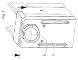
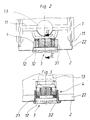
- the two radiator plates 1 are connected to one another in their upper region by T-shaped connecting pieces 13. Your connecting piece 12 protrudes outwards.
- the edges 22 of the side parts 2 made of thin sheet metal overlap the outer side edge sections 11 of the radiator plates 1.
- the plastic sleeve 4 shown in FIGS. 5-7 is blown onto the connecting piece 12.
- the collar sleeve 3 which passes through the bore 21 in the side part 2, is placed in a latching manner, and its outer collar 32 rests on the outside of the side part 2 and thus holds it securely.
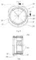
- the plastic sleeve 4 shown in FIGS. 5-6 has a sleeve shaft 41, on the outer end of which a section which is resilient in the radial direction is formed by arranging the axially parallel slots 412 through which the resilient tongues 413 are formed.
- tabs 42 are formed in a conically widening outer section by adaptation recesses 43. The length and the inner dimensions of this plastic sleeve 4 are chosen so that this plastic sleeve 4 between the outer collar of the connecting piece 12 and the lateral pipe exits of the T-shaped connector 13 can be blasted.
- concentric toothings are provided in the two diametrically opposite partial angle regions ⁇ , which can also be designed as partial thread sections.
- the collar sleeve 3 which is designed on the inside in a corresponding manner, can be snapped on or fixed by twisting.
- the inner diameter of the sleeve shaft 31 of the collar sleeve is therefore chosen accordingly.
- An internal toothing 311 is formed in the corresponding partial areas in the sleeve shaft 31. The collar sleeve 3 is held in the bore 21 of the side part 2.
- a groove 315 is provided between the outer collar 32 and an inner annular shoulder 314, the width of which is slightly larger than the sheet metal thickness of the side part 2 or as the thickness of an inwardly directed bend.
- This ringför shoulder 314 has run-on surfaces with the aid of which the collar sleeve 3 can be pushed into the side part 2 until it locks in the groove 315.
- an axially parallel web 312 is formed on the outside of the sleeve shaft 31, which corresponds to a corresponding edge recess in the bore 21 of the side part 2.
- the toothing or thread connection between the sections 311 and 411 can be released or closed by a corresponding rotation of approximately 90 °.
- the collar 32 is very narrow and has key surfaces 321 for the engagement of a corresponding key.
Landscapes
- Engineering & Computer Science (AREA)
- Physics & Mathematics (AREA)
- Thermal Sciences (AREA)
- Mechanical Engineering (AREA)
- General Engineering & Computer Science (AREA)
- Connection Of Plates (AREA)
- Clamps And Clips (AREA)
- Laminated Bodies (AREA)
- Dowels (AREA)
- Resistance Heating (AREA)
- Baking, Grill, Roasting (AREA)
Applications Claiming Priority (2)
| Application Number | Priority Date | Filing Date | Title |
|---|---|---|---|
| DE9014178U DE9014178U1 (de) | 1990-10-12 | 1990-10-12 | Mehrplattenheizkörper |
| DE9014178U | 1990-10-12 |
Publications (2)
| Publication Number | Publication Date |
|---|---|
| EP0480184A1 EP0480184A1 (de) | 1992-04-15 |
| EP0480184B1 true EP0480184B1 (de) | 1993-08-04 |
Family
ID=6858314
Family Applications (1)
| Application Number | Title | Priority Date | Filing Date |
|---|---|---|---|
| EP91115243A Expired - Lifetime EP0480184B1 (de) | 1990-10-12 | 1991-09-10 | Mehrplattenheizkörper |
Country Status (4)
| Country | Link |
|---|---|
| EP (1) | EP0480184B1 (da) |
| AT (1) | ATE92607T1 (da) |
| DE (2) | DE9014178U1 (da) |
| DK (1) | DK0480184T3 (da) |
Cited By (1)
| Publication number | Priority date | Publication date | Assignee | Title |
|---|---|---|---|---|
| DE19805862C1 (de) * | 1998-02-13 | 1999-04-08 | Wiemann Gmbh | Vorrichtung zum Ausrichten einer Heizkörperverkleidung |
Families Citing this family (4)
| Publication number | Priority date | Publication date | Assignee | Title |
|---|---|---|---|---|
| DE29801129U1 (de) | 1998-01-23 | 1998-03-26 | Caradon Heating Europe B.V., Zaventem | Heizkörperverkleidung |
| DE29500101U1 (de) * | 1995-01-04 | 1995-03-02 | Thermo-Technik Büdingen GmbH TTB, 63654 Büdingen | Anschlußelement für einen Heizkörper |
| DE29607615U1 (de) * | 1996-04-26 | 1996-07-11 | Förster, Wolfgang, 58675 Hemer | Mehrplattenheizkörper |
| ITMI20111928A1 (it) * | 2011-10-25 | 2013-04-26 | Radiatori 2000 S P A | Termoconvettore e metodo di realizzazione di detto convettore |
Family Cites Families (3)
| Publication number | Priority date | Publication date | Assignee | Title |
|---|---|---|---|---|
| DE8502780U1 (de) * | 1985-02-01 | 1985-05-30 | Kermi GmbH, 8350 Plattling | Verkleideter plattenheizkoerper und haltevorrichtung fuer die verkleidung von plattenheizkoerpern |
| DE8809545U1 (de) * | 1988-07-22 | 1988-09-29 | Kermi GmbH, 8350 Plattling | Plattenheizkörper |
| DE8903087U1 (de) * | 1989-03-13 | 1990-07-12 | Vogel & Noot AG, Wartberg | Heizkörper |
-
1990
- 1990-10-12 DE DE9014178U patent/DE9014178U1/de not_active Expired - Lifetime
-
1991
- 1991-09-10 EP EP91115243A patent/EP0480184B1/de not_active Expired - Lifetime
- 1991-09-10 AT AT91115243T patent/ATE92607T1/de not_active IP Right Cessation
- 1991-09-10 DE DE9191115243T patent/DE59100255D1/de not_active Expired - Fee Related
- 1991-09-10 DK DK91115243.7T patent/DK0480184T3/da active
Cited By (1)
| Publication number | Priority date | Publication date | Assignee | Title |
|---|---|---|---|---|
| DE19805862C1 (de) * | 1998-02-13 | 1999-04-08 | Wiemann Gmbh | Vorrichtung zum Ausrichten einer Heizkörperverkleidung |
Also Published As
| Publication number | Publication date |
|---|---|
| DE9014178U1 (de) | 1990-12-20 |
| EP0480184A1 (de) | 1992-04-15 |
| DE59100255D1 (de) | 1993-09-09 |
| ATE92607T1 (de) | 1993-08-15 |
| DK0480184T3 (da) | 1994-01-03 |
Similar Documents
| Publication | Publication Date | Title |
|---|---|---|
| EP3384167A1 (de) | Verstellbare distanzhülse | |
| EP0675308A1 (de) | Rohrmanschette | |
| DE2056725A1 (de) | Elektromechanische Zugvorrichtung zu schienengeführten Gehängen, insbes. Vorhängen | |
| EP0480184B1 (de) | Mehrplattenheizkörper | |
| EP0824170B1 (de) | Befestigungsvorrichtung für einen zur Wandmontage von sanitären Elementen verwendeten Anchlussfitting | |
| CH670125A5 (en) | Two-dia. screw with two threaded portions - has larger thread on sleeve turning but not sliding on shank | |
| AT1946U1 (de) | Schublade | |
| DE3532985A1 (de) | Schmutzfaenger fuer kraftfahrzeuge | |
| DE102015013926A1 (de) | Covering rosette for a concealed sanitary fitting | |
| DE2553263C2 (de) | Befestigungselement zur Halterung von C-förmigen Profilen an Rahmen, Tragschienen o.dgl. | |
| EP0672559B1 (de) | Verschlusseinrichtung zum lösbaren Verbinden zweier Bauteile | |
| DE3518813A1 (de) | Flansch zur befestigung von rohren | |
| DE3223284A1 (de) | Vorrichtung zur radialen und axialen verschiebungssicherung eines teils auf einer rotierenden welle | |
| EP1324898A1 (de) | Vorrichtung zur verbindung eines trägers, insbesondere eines karosserieteils eines kraftfahrzeuges, mit einem plattenelement, insbesondere einer tür- oder wandverkleidung | |
| EP0898919B1 (de) | Verstellelement für eine Duschvorrichtung oder dgl. | |
| DE9000484U1 (de) | Schublade mit Aufsatzrahmen | |
| DE9413608U1 (de) | Beschlag für Türen und Fenster | |
| DE29707971U1 (de) | Verkleidung für einen Flachheizkörper | |
| DE20004018U1 (de) | Drehgriff | |
| DE69317511T2 (de) | Mechanismus zur Verbindung und Verriegelung einer Konsole eines Rolladens | |
| DE2419462B2 (da) | ||
| DE29602573U1 (de) | Mehrplattenheizkörper | |
| DE102017126679B4 (de) | Kraftfahrzeug mit einer Karosserie und einem in eine Aufnahmeöffnung der Karosserie eingesetzten Bauteil | |
| DE69204589T2 (de) | Nichtabmontierbares Zwischenstück, insbesondere zum Einstellen der Orientierung von Fahrzeugscheinwerfern. | |
| DE20213314U1 (de) | Drehgriff zur Betätigung eines Schlosses einer Tür oder eines Fensters |
Legal Events
| Date | Code | Title | Description |
|---|---|---|---|
| PUAI | Public reference made under article 153(3) epc to a published international application that has entered the european phase |
Free format text: ORIGINAL CODE: 0009012 |
|
| AK | Designated contracting states |
Kind code of ref document: A1 Designated state(s): AT BE DE DK FR GB NL SE |
|
| 17P | Request for examination filed |
Effective date: 19920917 |
|
| 17Q | First examination report despatched |
Effective date: 19930126 |
|
| GRAA | (expected) grant |
Free format text: ORIGINAL CODE: 0009210 |
|
| AK | Designated contracting states |
Kind code of ref document: B1 Designated state(s): AT BE DE DK FR GB NL SE |
|
| REF | Corresponds to: |
Ref document number: 92607 Country of ref document: AT Date of ref document: 19930815 Kind code of ref document: T |
|
| GBT | Gb: translation of ep patent filed (gb section 77(6)(a)/1977) |
Effective date: 19930806 |
|
| REF | Corresponds to: |
Ref document number: 59100255 Country of ref document: DE Date of ref document: 19930909 |
|
| ET | Fr: translation filed | ||
| REG | Reference to a national code |
Ref country code: DK Ref legal event code: T3 |
|
| PLBE | No opposition filed within time limit |
Free format text: ORIGINAL CODE: 0009261 |
|
| STAA | Information on the status of an ep patent application or granted ep patent |
Free format text: STATUS: NO OPPOSITION FILED WITHIN TIME LIMIT |
|
| 26N | No opposition filed | ||
| PGFP | Annual fee paid to national office [announced via postgrant information from national office to epo] |
Ref country code: FR Payment date: 19940919 Year of fee payment: 4 |
|
| PGFP | Annual fee paid to national office [announced via postgrant information from national office to epo] |
Ref country code: AT Payment date: 19940922 Year of fee payment: 4 |
|
| PGFP | Annual fee paid to national office [announced via postgrant information from national office to epo] |
Ref country code: SE Payment date: 19940923 Year of fee payment: 4 Ref country code: DK Payment date: 19940923 Year of fee payment: 4 |
|
| PGFP | Annual fee paid to national office [announced via postgrant information from national office to epo] |
Ref country code: NL Payment date: 19940930 Year of fee payment: 4 |
|
| PGFP | Annual fee paid to national office [announced via postgrant information from national office to epo] |
Ref country code: BE Payment date: 19941007 Year of fee payment: 4 |
|
| EAL | Se: european patent in force in sweden |
Ref document number: 91115243.7 |
|
| PG25 | Lapsed in a contracting state [announced via postgrant information from national office to epo] |
Ref country code: GB Effective date: 19950910 Ref country code: DK Effective date: 19950910 Ref country code: AT Effective date: 19950910 |
|
| REG | Reference to a national code |
Ref country code: DK Ref legal event code: EBP |
|
| PG25 | Lapsed in a contracting state [announced via postgrant information from national office to epo] |
Ref country code: SE Effective date: 19950911 |
|
| PG25 | Lapsed in a contracting state [announced via postgrant information from national office to epo] |
Ref country code: BE Effective date: 19950930 |
|
| BERE | Be: lapsed |
Owner name: FIRMA WOLFGANG FORSTER Effective date: 19950930 |
|
| PG25 | Lapsed in a contracting state [announced via postgrant information from national office to epo] |
Ref country code: NL Effective date: 19960401 |
|
| GBPC | Gb: european patent ceased through non-payment of renewal fee |
Effective date: 19950910 |
|
| PG25 | Lapsed in a contracting state [announced via postgrant information from national office to epo] |
Ref country code: FR Effective date: 19960531 |
|
| NLV4 | Nl: lapsed or anulled due to non-payment of the annual fee |
Effective date: 19960401 |
|
| EUG | Se: european patent has lapsed |
Ref document number: 91115243.7 |
|
| REG | Reference to a national code |
Ref country code: FR Ref legal event code: ST |
|
| PGFP | Annual fee paid to national office [announced via postgrant information from national office to epo] |
Ref country code: DE Payment date: 20000718 Year of fee payment: 10 |
|
| PG25 | Lapsed in a contracting state [announced via postgrant information from national office to epo] |
Ref country code: DE Free format text: LAPSE BECAUSE OF NON-PAYMENT OF DUE FEES Effective date: 20020501 |