EP0480193A2 - Verzweigungsvorhersagemechanismus mit mehreren Voraussagen - Google Patents
Verzweigungsvorhersagemechanismus mit mehreren Voraussagen Download PDFInfo
- Publication number
- EP0480193A2 EP0480193A2 EP91115459A EP91115459A EP0480193A2 EP 0480193 A2 EP0480193 A2 EP 0480193A2 EP 91115459 A EP91115459 A EP 91115459A EP 91115459 A EP91115459 A EP 91115459A EP 0480193 A2 EP0480193 A2 EP 0480193A2
- Authority
- EP
- European Patent Office
- Prior art keywords
- instruction
- branch
- branch prediction
- address
- fetch
- Prior art date
- Legal status (The legal status is an assumption and is not a legal conclusion. Google has not performed a legal analysis and makes no representation as to the accuracy of the status listed.)
- Withdrawn
Links
Images




Classifications
-
- G—PHYSICS
- G06—COMPUTING OR CALCULATING; COUNTING
- G06F—ELECTRIC DIGITAL DATA PROCESSING
- G06F9/00—Arrangements for program control, e.g. control units
- G06F9/06—Arrangements for program control, e.g. control units using stored programs, i.e. using an internal store of processing equipment to receive or retain programs
- G06F9/30—Arrangements for executing machine instructions, e.g. instruction decode
- G06F9/38—Concurrent instruction execution, e.g. pipeline or look ahead
- G06F9/3802—Instruction prefetching
- G06F9/3804—Instruction prefetching for branches, e.g. hedging, branch folding
- G06F9/3806—Instruction prefetching for branches, e.g. hedging, branch folding using address prediction, e.g. return stack, branch history buffer
-
- G—PHYSICS
- G06—COMPUTING OR CALCULATING; COUNTING
- G06F—ELECTRIC DIGITAL DATA PROCESSING
- G06F9/00—Arrangements for program control, e.g. control units
- G06F9/06—Arrangements for program control, e.g. control units using stored programs, i.e. using an internal store of processing equipment to receive or retain programs
- G06F9/30—Arrangements for executing machine instructions, e.g. instruction decode
- G06F9/38—Concurrent instruction execution, e.g. pipeline or look ahead
- G06F9/3836—Instruction issuing, e.g. dynamic instruction scheduling or out of order instruction execution
- G06F9/3842—Speculative instruction execution
- G06F9/3848—Speculative instruction execution using hybrid branch prediction, e.g. selection between prediction techniques
Definitions
- the present invention generally relates to the field of data processing and, more particularly, to predicting the outcome of conditional branches, either taken or not taken, in the processor of a computer.
- FIG. 1 shows the major components that make up a processor's pipeline. The components are: Instruction fetch (stage I), instruction decode and address generation (stage II), operand fetch (stage III), instruction execution (stage IV), and put away of the results (stage V). Each instruction enters the pipeline and ideally spends one cycle at each stage of the pipeline. Individually, each instruction takes five cycles to pass through the pipeline.
- each component of the processor can be kept actively working on a different instruction, each at a different pipeline stage, and one instruction can complete in every cycle.
- keeping the pipeline full is a difficult task. Breaks in the pipeline, disruptions, frequently occur and result in idle cycles that can delay an instruction's execution.
- the branch instruction is one of the major causes of a pipeline disruption.
- the branch instruction introduces a temporary uncertainty into the pipeline because, in order to keep the pipeline full, the processor must guess which one of two possible instructions enters the pipeline next; the fall through instruction or the target of the branch. Most high performance processors will guess the outcome of the branch before it executes and then proceed to fetch and decode instructions down the path that is guessed (either taken or not taken).
- the processor can keep the pipeline full of instructions and, if the outcome of the branch is guessed correctly, avoid a pipeline disruption. If the branch was guessed incorrectly, for example a guess of not taken and the branch is actually taken, then any of the instructions that entered the pipeline following the branch are canceled and the pipeline restarts at the correct instruction.
- the table is referred to as a Decode History Table (DHT), and combinatorial logic determines the guess from the value found in the table. No attempt is made to predict the branch target, since this is known at decode time; just the outcome of the branch is predicted.
- the DHT is used to predict the outcome of only the conditional branches since the outcome of each unconditional branch is explicitly known once it is decoded.
- U.S. Pat No. 3,325,785 to Stephens describes a mechanism by which the outcome of branch is predicted based on the type of branch and statistical experience as to whether the branch will be taken.
- Another branch strategy describes suspending the pipeline until the branch is fully executed. The outcome of the branch is then known, either taken or not taken, and the correct instruction can then be fetched and processed through the pipeline. This strategy, however, results in several cycles of pipeline delay (idle cycles) per branch.
- U.S. Patent No. 4,181,942 to Forster et al. describes a mechanism by which a special branch instruction is used in a processor to indicate the type of branch, either conditional or unconditional as determined by the state of an internal register.
- the special branch instruction is used for program control at the end of a program loop and for unconditional branching outside of the loop.
- U.S. Patent No. 4,200,927 to Hughes et al. describes a mechanism by which multiple instruction buffers are addressed and filled based on the prediction of each branch that is encountered in the instruction stream.
- the prefetching of instructions into each instruction buffer and the selection of one of the instruction buffers for gating instructions into the decoder is controlled by logic which keeps track of the status of each instruction stream and branch contained in each instruction buffer. Branches are guessed based on their type, and result signals from the instruction execution unit, in response to the execution of conditional branch instructions, will control the setting of various pointers to allocate new instruction streams to instruction buffers and to de-allocate or reset the instructions streams based on the results of branches execution.
- Each instruction fetch made by the processor is compared against each branch address saved in the BHT and, if a match occurs, then a branch is assumed to be taken and the target-address, also in the table, becomes the next instruction-fetch address.
- each instruction fetch address found in the table is predicting that a branch instruction will be found at that address and that the branch will be taken to the same address as specified by the target-address saved in the BHT. If no entry is found in the BHT, then it is assumed that there is not a branch within the instruction-fetch address (address of the instruction doubleword that is being fetched) or, if there is a branch, it is not taken.
- U.S. Patent 4,679,141 to Pomerene et al. describes a branch prediction mechanism that improves the BHT as described in U.S. Patent 3,559,183.
- the BHT is improved by dividing it into two parts; an active area and a backup area.
- the active area contains entries for a small subset of branches which the processor has encountered and the backup area contains all of the other branch entries. Mechanisms are described to bring entries from the backup area in the active area ahead of when the processor will use those entries.
- the small size of the active area allows it to be fast and optimally placed in the processor's physical layout.
- each entry of a BHT consists of two addresses, the branch address followed by the predicted target- address whereas each entry in a DHT is represented by a single bit, indicating if the branch is taken or not taken.
- a BHT with 1K entries consists of 1024, two address pairs (i.e., 1024 x 64 bits), where each entry is represented by 64 bits.
- a branch prediction mechanism predicts each branch at least twice, first during the instruction-fetch phase of the pipeline and then again during the decode phase of the pipeline.
- the mechanism uses two different branch prediction mechanisms, each a separate and independent mechanism from the other. The mechanism then describes a set of rules to predict the branch whenever the two separate branch prediction mechanisms disagree.
- the preferred choice for the instruction-fetch-time prediction mechanism is the BHT and the preferred decode-time prediction mechanism is the DHT.
- Each mechanism is preferred because, independently, the prediction accuracy of each mechanism is very high and, when combined, even higher guess accuracy rates are obtained. For example, it is not uncommon for a BHT or DHT comprised of 4K entries to successfully predict the outcome of over 80% of the branches encountered by the processor. However, other decode-time or instruction-fetch mechanisms can be substituted as desired.
- the operations of a processor with a standard BHT or a DHT are described as a prelude to describing the operation of the present invention with multi-prediction branch prediction.
- the BHT must be able to predict a high percentage of its branches correctly because there is a severe penalty when it is wrong. Normally, many of the prediction errors made by the BHT are discovered only after the branch is executed. Several cycles of delay can be saved if each error can be predicted earlier.
- the BHT makes its prediction during the instruction-fetch phase of the pipeline and that it can be several cycles until the branch is finally executed.
- the DHT By using the DHT to re-predict the outcome of each conditional branch encountered by the processor it is possible to detect a potential prediction error made by the BHT during the decode phase of the pipeline. The processor can then be redirected to the correct instruction stream thus saving several cycles of delay.
- the prediction process is now explained.
- the BHT is used much in the manner described above while the DHT is used to confirm the branch predictions made by the BHT and, in certain cases when the predictions differ, override the prediction made by the BHT.
- both predictions are in agreement, either both taken or both not taken, there is no need to override any branch prediction.
- a decision as to the outcome of the branch, either taken or not taken must be made. For example, consider the case where the initial prediction made by the BHT is that the branch is "not taken" and that the DHT predicts that the branch will be "taken".
- a DHT with 16K entries working in conjunction with a BHT with 1K entries represents significantly less hardware than a BHT with 2K entries.
- the 1K BHT and 16K DHT can predict a greater percentage of the branches correctly and thus provide an increase in performance over a larger BHT.
- Fig. 2 shows the essential features of a processor that has a BHT. The actions of each component are described in accordance with the each pipeline phase shown in Fig. 1. Each phase is described separately; however, as in any pipeline processor, all phases of the pipeline occur in parallel.
- Instructions are stored in memory 10 and are fetched from the memory 10 and stored in cache 13, according to well known mechanisms.
- the instruction-buffer 11 signals the BHT 12 via the "instruction-buffers not full" signal that space is available for another instruction fetch.
- the BHT then generates the next-instruction- fetch and sends the address to the cache 13.
- the I-fetch segment is then returned from the cache via path 14.
- the BHT 12 signals the instruction-buffer 11 via path 15 to load the next-instruction register 16 with the appropriate next instruction.
- the instruction loaded can be either the instruction immediately following the previous instruction loaded, i.e., the "next-sequential instruction", or a branch-target instruction, depending of the information sent from the BHT.
- the instruction decode register 17 is loaded from the next-instruction register 16.
- the instruction is decoded and operation code (op-code) and execution information is assembled. After decoding the instruction, the execution information is sent to the execution unit 18 where it is held until execution. If operands are required by the instruction, then the necessary information (base register values, index register, and displacements) are sent to the address generate mechanism 19.
- the output of the address-generate mechanism 19 is an address for an operand. The address is then sent to the cache 13.
- the cache then sends the operand information back to the execution unit 18 via path 21.
- the instruction waits at the execution unit 18 until the needed data is available from the cache 13. There, the instruction is executed and the results are put away as required. If a branch was executed, then the BHT update information is sent from the execution unit 18 back to the BHT 12 via path 22. The BHT update information is sent to assure that the BHT is correctly predicting the outcome of each branch. Finally, the Endop (end operation) function 23 is issued to mark the point in time when the instruction is successfully completed.
- the instruction-length information, generated by the decode mechanism 17, is sent to the address adder 25. There it is combined with the value from the instruction-counter (IC) register 26 to form the next-instruction address.
- the output from the address adder 25 is then sent to the update- instruction-counter register 27 and to the BHT 12 via line 28.
- the update-instruction-counter register 27 will then hold the value of the instruction to be decoded on the next cycle. This sequence of events is then repeated by the processor for the next cycle.
- the BHT is used to effectively direct the instruction fetching policies of a processor and improve branch prediction accuracy by directing the right instruction, either the next sequential or branch target, to the decoder. To do this, it must examine the address of each instruction fetch made by the processor and detect when there is a taken branch contained within an instruction-fetch segment. Each instruction fetch is held in the instruction-fetch address-register 31. This address is compared by compare function 33 against each branch address held in the BHT directory 32.
- each instruction-fetch segment contains more than one instruction. In present machines, an instruction-fetch segment is several words long (ie.
- BHT-hit Any instruction-fetch address that matches a branch address contained in the BHT will be termed a "BHT-hit”.
- BHT-miss is used to denote an instruction-fetch segment that misses all of the branch addresses contained in the BHT. That is, the address of the instruction fetch fails to compare with any of the instruction fetch segments held in the BHT directory.
- next instruction-fetch address made by the processor is the "next sequential" instruction-fetch segment, as determined by next sequential logic 34. If the instruction-fetch address "hits in the BHT", then the processor will switch instruction streams, and the next-instruction address segment generated by the processor is the target-address of the BHT entry that caused the "hit". The new target-address goes to gate 35 and becomes the new instruction-fetch address when a BHT-hit is detected. The next-sequential instruction-fetch is called for when a BHT-miss is detected via gate 36.
- the branch-address (BA) and target-address (TA) are saved in the branch-address, target-address (BA/TA) stack 37, and the target-address becomes the next instruction-fetch address on the following cycle.
- the BA/TA stack is used to guide the pre-loading of instructions from the instruction-buffer to the next-instruction-register.
- the information to load the instruction-buffer is sent via path 15.
- the information, an address, used to load the instruction buffer is obtained by comparing the branch-address of the oldest entry in the BA/TA stack 37 to the next-instruction-address sent via path 28.
- next-instruction-address should become the target-address for the BA/TA pair in the stack 37. Note, that this will happen if the BHT is correct in predicting the action of the branch.
- the target-address, for the BA/TA pair that matched is held in function block 42 and signals unit 43 to select this address for the next-instruction address on path 15. If the compare in function 41 is not equal, then no select is issued and the next-instruction address from path 28 becomes the next-instruction address sent via path 15.
- the BA/TA pair is then removed from stack 37 and the process continues with the next oldest BA/TA pair found on the stack.
- the last-segment-fetch register inside the next-sequential fetch controls next sequential logic 34, is loaded with the target-address value. Whenever a "next-sequential" instruction fetch is called for, the value saved in the last-instruction-fetch register is bumped (increased by one unit) to the address of the next-instruction-fetch segment and becomes the new instruction-fetch address.
- BHT prediction errors can be detected after the address-generation phase of an instruction or after the execution phase. BHT prediction errors that are discovered after the branch is executed incur the full pipeline delay. A signal to "restart the pipeline” is sent by the execution unit to the BHT whenever it is discovered that the outcome of a branch is different from the predicted action, taken or not taken. The restart information along with BHT correction information is sent via path 22.
- the pipeline can be "restarted earlier” by detecting a BHT error after the instruction decode and AGEN phase of the pipeline. This avoids several cycles of pipeline delay that would result by detecting a branch prediction error in the execution unit after the branch is executed.
- a BHT prediction error can be detected at decode time whenever the BHT has predicted that there is no branch, a BHT miss, and the DECODER then decodes an unconditional branch. This information can also be sent to the BHT via path 22.
- An error in predicting the target-address of a branch can be detected after the address-generate function 19 and is made available to the BHT 12 via path 28, as shown in Fig. 2.
- the target address of the branch (the output of the address-generate function 19) is sent to the BHT 12 and compared against the predicted target-addresses held in the BA/TA stack 37 in Fig. 3. This logic is contained in function 40 of Fig. 3.
- a correction is necessary.
- the target-address saved in the BHT entry must be changed to reflect the new, or current, target-address of the branch instruction. Corrections are sent via path 46 to the BHT directories 32.
- Pipeline restart information is sent via path 45 and is used to reload the I-fetch-address register 31 and purge the BA/TA stack 37. The effects of a pipeline restart are discussed below.
- BHT corrections are also detected after the execution phase of an instruction.
- Correction information is sent via path 22.
- the outcome of each branch, either taken or not taken is sent to the BHT and compared against the predicted status of each branch currently held in the BA/TA stack 37. This is done in unit 47. If an error was in failing to predict a taken branch, then a new entry is made in the BHT directory. The new BA/TA information is sent to the BHT via path 46. If the error was predicting that a branch will be taken and if it is in fact not taken, then the BA/TA entry currently held in the BHT must be deleted. This correction information is also sent to the BHT via path 46.
- the pipeline will have to be restarted. For example, consider the case were a branch was predicted as not taken and the branch was actually taken.
- the instruction fetching mechanism of the BHT was such that the target of the branch was never fetched and now the pipeline is idle until the correct instruction information is fetched and put in the instruction buffer. Once the correct instruction is fetched from the cache, the normal pipeline flow can continue.
- the restart logic will cause the instruction-fetch-address 31 to be loaded with a new instruction address (in this case the target of branch). This allows the instruction-fetching sequence to begin anew.
- the "pipeline restart” procedure also causes the instruction-buffer 11 in Fig.
- FIG. 4 shows the essential features of a processor with a DHT.
- the figure shows that a processor with a DHT shares many of the features found in a processor having a BHT. However, the main difference is that the DHT only predicts the outcome of each conditional branch, either taken or not taken, and that the instruction fetching logic of a BHT is replaced with a much simpler mechanism that can only generate "next sequential" fetches.
- the cache 13 again supplies instruction-fetch information to the instruction-buffer 11.
- the instruction-buffer (IB) 11 holds the instruction-fetch segments that have been returned from the cache 13.
- restart information to restart the pipeline if the prediction made by the DHT is wrong
- instruction-fetch information instruction-fetch segments for each instruction stream currently in the pipeline
- alternate instruction path information for example, a detailed description of a multi-instruction stream multi-instruction buffer processor can be found in U.S.
- next-instruction register 16 is loaded from the instruction buffers.
- the instruction-buffers use the next-instruction address, which is input to the update-instruction-counter (update-IC) 27 to determine which instruction to load into the next-instruction-register 16.
- the instruction decode logic 17 produces the following outputs:
- the address-adder 25 then combines the instruction-length value with the instruction-counter value 26 to produce the next-instruction address. This value is then saved in the update-instruction-counter 27. Operand addresses are computed in the address-generate unit 19, and the fetch requests and addresses are sent to the cache 13. Operands are returned to the execution unit 18 via path 21. There, the instruction is executed and the results put away. The Endop unit 23 then signals the completion of the instruction.
- the decoder 17 detects an unconditional branch.
- the target-address of the branch (which is an instruction) is fetched from the cache 13 and the target instruction is loaded into the next-instruction register 16 via path 21 and gate 51.
- the target-address of the branch is made available from the address generate-mechanism 19.
- the target-address is also sent to the update-IC 27, and the sequential-prefetching-control (SPC) 52 via paths 53 and 54, respectively.
- SPC 52 will then begin to fetch instruction segments starting with the "new" target-address of the branch.
- the DHT 55 will be accessed via path 91 to predict the outcome of the branch, either taken or not taken.
- the DHT 55 uses a subset of the address bits, contained in the instruction-counter 26, to examine the DHT array contained in the DHT 55. If the prediction of the branch "is taken", then the target-address is fetched similarly as was the target-address for the unconditional branch. That is, the target-address is fetched from the cache 13 and the target instruction is loaded into the next-instruction register 16 via gate 51.
- the target-address is also sent to the update-IC 27 via path 53, and the DHT 55 signals the sequential-prefetching-control 52 via path 56 to reset its instruction-fetch address to the predicted-target-address of the branch to begin new next-sequential fetches.
- the target-address of the branch is sent to the SPC 52 via path 54.
- Instruction-fetch logic is contained in the sequential-prefetching-controls (SPC) 52.
- SPC sequential-prefetching-controls
- Fig. 5 gives a more detailed description of this mechanism.
- the address of the last instruction-fetch is saved in the last-segment-fetched register 61 and whenever the instruction buffers signal the SPC 52 that space is available for another instruction-fetch, via gate 62, the next-sequential instruction-fetch-address is generated and sent to the cache 13.
- the SPC 52 is signaled via path 56 to reset its instruction-fetch-address to the target-address of the branch instruction
- the last-block-fetched register 61 is loaded with the target-address of the branch.
- This address is provided by the address-generate function 19. Thereafter, all next sequential fetches can be generated from within the SPC 52.
- the target-address is sent to the SPC 52 via path 54 and loaded through gate 63 on a signal from the DHT 55, via path 56, that an unconditional branch or predicted taken conditional branch was decoded.
- Branch predictions are made by the DHT 55.
- Fig. 6 gives a more detailed description of a DHT.
- the DHT is signaled from the decode-function 17, via path 91, whenever a conditional branch is decoded.
- the DHT array 71 is accessed by using a subset of the bits that represent the instruction address, held in the instruction-counter register 26. Each array entry consists of only a single bit whose value represents the outcome of a branch at this memory location, up to the size of the table.
- DHT-hit corresponds to the terms used for a BHT, i.e., a "BHT-hit” and "BHT-miss”, and denote if the branch is predicted as taken or not-taken, respectively.
- DHT correction information is sent to the DHT from the execution unit 18, via path 22.
- the correction information contains the results of the branch's execution, either taken or not taken, and the address of the branch.
- the DHT is updated using this information. Since the DHT only predicts the action of each conditional branch, only the execution results of each branch needs to be returned to the DHT.
- Figs. 7A and 7B shows sets of rules in tabular form that summarize the events and actions that occur in these processors. The events are listed according to decode-time and instruction-fetch time actions, and BHT and DHT hit or miss results.
- the Fig. 7A shows that a "BHT-hit" (a prediction of taken) causes the instruction fetching mechanism to switch to the target-address of the branch (at instruction-fetch time).
- BHT-hit a prediction of taken
- the instruction fetching mechanism will continue to fetch instructions down the next sequential path.
- the decoder will switch to the target-address stream as identified by the BHT-hit or continue to decode down the next sequential path if no BHT entry was found (a BHT-miss).
- Fig. 7B The actions taken for a processor with a DHT are different, as shown in Fig. 7B.
- the instruction-fetch mechanism can only fetch the next-sequential instructions regardless of any prediction outcome. However, if a branch is discovered at decode time and predicted as taken (a DHT hit) then the instruction fetching mechanism will begin to fetch instruction segments down the target-address path. Similarly, the decoder will switch to decode instructions down the target-address path when a DHT hit occurs. If the prediction is a DHT miss, then the processor will continue to fetch instructions down the next-sequential path and also decode the fall-through instruction on the next cycle.
- a multi-prediction branch prediction mechanism uses both a BHT and DHT to predict branches and in so doing improves the prediction process by offering features that neither prediction mechanism (DHT/BHT) can provide separately. These extra features will then improve overall branch prediction accuracy and thus improve performance.
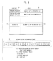
- Fig. 8 shows a table that summarizes the events and actions that describe the current invention. Each BHT-hit is now divided into two categories: an "active-taken-hit" and a "ghost-hit".
- FIG. 9 is used to explain these differences in detail.
- the figure shows the format for the BHT directory, array, and block entries.
- Each directory entry 81 represents the address of an instruction-fetch segment that contains as least one previously executed taken branch.
- the array information 82 associated with each directory entry, identifies (a) the address of each taken branch contained within an instruction-fetch segment, (b) the target-address of each branch, (c) a taken, not-taken bit, (d) a valid bit, and (e) LRU usage bits.
- the target-address must be a full instruction address since a branch can branch to any instruction-fetch segment.
- the target-address can be abbreviated or truncated when stored in the BHT. It is possible to save only a subset of the low order bits that make up the full target-address.
- the full target-address can then be reconstructed by concatenating the current high order bits from the instruction-counter register to the low order bit saved in the BHT. This technique tries to take advantage of the observation that branches typically jump a short distance and very little accuracy will be lost in generating the full target-address from only a reduced set of address bits.
- the valid bit is used to denote which of BA/TA pairs in each block, up to four, are valid. As mentioned above, provisions are provided to remember up to four branch address within each instruction-fetch segment.
- the taken bit is needed because a branch can change its actions. That is, initially a branch must be taken to be entered into the BHT. However, in subsequent executions the branch can fail to be taken. This action would result in a BHT correction. Recall that a BHT correction occurs for all branches that are predicted as taken and then fail to be taken when executed. The correction mechanism must then "turn off" the taken bit for this BHT entry. If an instruction fetch segment matches a branch address with a "taken bit" turned off, then a ghost-hit is identified. Ghost hits are used to describe a hit to a BHT entry (a branch) that is no longer taken.
- LRU least-recently-used
- each BHT prediction (hit, ghost-hit, miss) is now paired with a DHT prediction (hit or miss).
- the events are listed according to the instruction-fetch and decode-time phases of the processor.
- a valid-BHT-hit causes the instruction fetch mechanism to fetch the target of the branch found in the BHT. This occurs regardless of the DHT prediction, hit or miss.
- the processor will switch to decode instructions from the target-address path. Instructions from the target-address path will be decoded by the processor for either a DHT hit or miss.
- each "ghost-hit" prediction causes the instruction-fetch mechanism to continue to fetch instructions from the next-sequential path.
- the processor will continue to decode down the next-sequential path regardless of the DHT prediction, a hit or a miss.
- the processor will continue to fetch the next-sequential segments.
- the processor will continue to decode instructions from the next-sequential path.
- the processor will stop fetching the next-sequential path and switch to fetch instructions from the target-address path.
- the target-address of the branch is available from the address generate function. When the target-address instructions are available in the instruction-buffer, the DECODER will also switch to decode instructions from the target address path identified by the branch.
- Fig. 10 shows the features of a processor according to the preferred embodiment of the invention that uses both a DHT and BHT for branch prediction. Most of the features in the figure have a similar functions as was described for a processor with just a BHT (Fig. 2) or a processor with a DHT (Fig. 4).
- the cache 13 supplies instructions to the instruction-buffer 11 as well as operands to the execution unit 18.
- the next-instruction-register 16 contains the next instruction to be processed by the instruction-decode-mechanism 17.
- the BHT 12 performs branch prediction, controls instruction fetching and directs the flow of instructions through the pipeline.
- the BHT 12 signals the instruction-buffer 11 to load the next-instruction-register 16 with the appropriate next instruction, either the next-sequential-instruction or branch-target-instruction.
- the next-instruction fetch is generated by the BHT 12 on a signal from the instruction buffer 11 that space is available.
- the next-instruction fetch can be either the next-sequential address or the target-address of a branch instruction, depending on the results of the previous instruction-fetch, a BHT-hit or BHT-miss.
- the operations of the DHT 55 are similar to the operation of a DHT described in Fig. 4. That is, the DHT 55 predicts conditional branches during the decode phase of the pipeline and signals the BHT via path 56 of the branch prediction results, either a hit or miss. Along with the branch prediction results, the address of the branch as well as the target-address of the branch is also supplied via path 56. This information will be used by the instruction-fetching logic in the BHT 12 to verify that the branch-predictions made by the BHT (made during the instruction-fetch phase of the pipeline) are correct. However, it is noted that the target-address of the branch is already supplied to the BHT 12 via path 28 and need not be duplicated via path 56. By including this information in the signal on path 56, the pipeline-restart and instruction-fetching-logic are simplified.
- the DHT 55 is signaled via path 91 from the instruction-decode-function 17 whenever a conditional branch is decoded.
- the address of the branch is supplied to the DHT 55 from the instruction-counter register 26.
- BHT and DHT corrections are signaled via path 22 from the execution unit 18.
- the address-adder mechanism 25 takes as its input the address of the current instruction being decoded, found in the IC register 26, and the length of the instruction being decoded and computes the next-instruction address. The new address is saved in the update-IC register 27.
- the DHT prediction logic for determining if a branch is taken or not-taken is the same as described in Fig. 6. This information is combined with the branch prediction logic found in the BHT to provide an improved branch scheme that neither a BHT or DHT can provide alone.
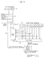
- Fig. 11 shows in detail how the correct BA/TA pair is selected from the BHT entries as described in Fig. 9.
- a "BHT-hit" is the result of an instruction-fetch-address 31, in Fig. 3, matching the address of an instruction-fetch-segment saved in the BHT 82, of Fig. 9.
- the comparative logic is contained in function 102.
- the instruction-fetch-address used in the comparison can be divided into two parts, 103 and 104. Part 103 is used to compare against each instruction-fetch-segment saved in the BHT.
- Part 104 represents a sub-address (SA) portion of the instruction-fetch address and identifies which instruction within an instruction-fetch-segment caused the BHT entry. This instruction would be a taken branch. This part of the address is not immediately needed in detecting a "BHT-hit". It is only used after an initial match of the instruction-fetch-address and the instruction-fetch-segment saved in the BHT. After a "BHT-hit" is detected, the correct branch within the instruction-fetch segment must be selected. Recall, there can be several taken branches within each instruction-fetch-segment.
- SA sub-address
- the desired branch is identified as the closest branch encountered after the instruction fetch address.
- the appropriate branch address is selected by the select logic 105 according to the following rules:
- the full BA is then created in the select gate logic 106.
- the selected BA 104 value from the select logic 105 is appended to the instruction-fetch-address 103 to create the full branch address.
- This address is then paired with the appropriate TA to form a BA/TA pair.
- the selected BA/TA pair is then saved in the BA/TA stack 37 of Fig. 3 to guide the later selection of the "next-instruction" from the instruction-buffer 11 into the next-instruction-register 16 of Fig. 2.
- the selected target-address is also gated to two other locations. First, the TA is used to update the next-instruction-fetch-address 31 of Fig. 3. Second, the target-address is used to reset the next-sequential-instruction-fetch control 34 of Fig. 3.
- the TA will also be sent to the instruction-fetch-register 31 and to the next-sequential-fetch mechanism 34.
- the selected TA becomes the next-instruction-fetch on all valid-taken-hits and is also used to reset the next-sequential-fetch controls 34.
- the prediction results of the DHT, provided via path 56, and the prediction made by the BHT, provided by the BA/TA stack 37, are examined in function 111.
- the BA of the oldest entry in the BA/TA stack 37 is compared to the address of the branch just decoded. If these addresses are not equal then the processor has decoded a branch that the BHT has predicted as not taken, a BHT-miss.
- the processing logic then proceeds to function 112 where the prediction made by the DHT is examined. If the DHT predicted that the branch will be taken, then it is assumed that the prediction made by the BHT is incorrect and the correct prediction is the DHT's.
- function 43 is signaled to load the instruction following the branch as the next-instruction loaded from the instruction-buffers to the next-instruction-register 16.
- Function 41 is again used to compare the next-instruction address, returned via path 28 against the BA of the oldest entry in the BA/TA stack 37. This guides the loading of instructions from the instruction-buffers into the next-instruction-register 16.
- Function 40 compares the target-address of a branch, calculated by the address-generate-function 19 of Fig. 2, with the target-address of the branch saved in the BA/TA stack 37. If the saved target-address is different than the generated target-address at decode, then the pipeline must be restarted. The restart information is sent via path 45. BHT corrections are sent to the correction-handling-stack 47.
- the execution results of each branch are checked with the predicted results and updates, new-entries, or branch deletions are scheduled to the BHT via update path 46 when necessary.
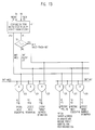
- Fig. 13 gives a detailed description of the comparative logic used to examine the predictions made by the BHT and DHT.
- Function 111 compares the address of the branch just decoded, sent via path 56, with the BA of the oldest entry in the BA/TA stack 37. If the addresses are equal, identifying a BHT-hit, then the taken, not-taken bit is examined in function 122. The output of function 122 determines if the selected branch is a valid-taken-bit or a ghost-hit. If the comparative logic of 122 determines that the branch address from the BA/TA stack 37 is not equal to the address of the decoded branch then a BHT-miss is identified.
- the select gates, 123 to 128, determine which of the instruction-fetch/decode-time policies to follow as described in Fig. 8.
- Each gate represents an AND gate and the output is sent to the following units (in Fig. 12):
- each branch is predicted twice, once during the instruction-fetch phase of the pipeline and then again at decode time.
- the embodiment uses a set of rules that determine the prediction whenever the two independent branch prediction policies disagree. More specifically, the two branch prediction schemes described in the embodiment are a BHT and a DHT. The set of rules to arbitrate any branch prediction differences are described in Fig. 8.
- the BHT and DHT are a preferred choice in branch prediction policies because each separately has a very high success rate in predicting branches, and when used together, an even higher percentage of branches can be guessed successfully.
- branch prediction can be according to op-code type as described in U.S. Patents No. 4,181,942 and No. 4,200,927. Either of these can be substituted for the BHT and DHT. Then, a set of rules, similar to the set of rules described in Fig. 8, is needed to resolve differences when the branch prediction schemes do not agree. In fact, a third branch prediction policy can be used to arbitrate those cases when the first two branch prediction schemes do not agree.
- branch prediction scheme possibly predicting each branch by its op-code type
- a multi-prediction branch prediction mechanism can consist of three separate branch prediction policies with the actual prediction of each branch being determined by an agreement of any two.
- a different branch prediction scheme can be substituted for those described for the preferred embodiment of the invention, or the existing branch prediction schemes can be modified within the scope of the invention.
Landscapes
- Engineering & Computer Science (AREA)
- Software Systems (AREA)
- Theoretical Computer Science (AREA)
- Physics & Mathematics (AREA)
- General Engineering & Computer Science (AREA)
- General Physics & Mathematics (AREA)
- Advance Control (AREA)
Applications Claiming Priority (2)
| Application Number | Priority Date | Filing Date | Title |
|---|---|---|---|
| US59452990A | 1990-10-09 | 1990-10-09 | |
| US594529 | 1996-01-31 |
Publications (2)
| Publication Number | Publication Date |
|---|---|
| EP0480193A2 true EP0480193A2 (de) | 1992-04-15 |
| EP0480193A3 EP0480193A3 (en) | 1994-09-14 |
Family
ID=24379263
Family Applications (1)
| Application Number | Title | Priority Date | Filing Date |
|---|---|---|---|
| EP9191115459A Withdrawn EP0480193A3 (en) | 1990-10-09 | 1991-09-12 | Multi-prediction branch prediction mechanism |
Country Status (3)
| Country | Link |
|---|---|
| US (1) | US5353421A (de) |
| EP (1) | EP0480193A3 (de) |
| JP (1) | JPH0820950B2 (de) |
Cited By (1)
| Publication number | Priority date | Publication date | Assignee | Title |
|---|---|---|---|---|
| WO2002008895A1 (en) * | 2000-07-21 | 2002-01-31 | Koninklijke Philips Electronics N.V. | Data processor with branch target buffer |
Families Citing this family (59)
| Publication number | Priority date | Publication date | Assignee | Title |
|---|---|---|---|---|
| WO1992006426A1 (en) * | 1990-10-09 | 1992-04-16 | Nexgen Microsystems | Method and apparatus for parallel decoding of instructions with branch prediction look-up |
| US5434985A (en) * | 1992-08-11 | 1995-07-18 | International Business Machines Corporation | Simultaneous prediction of multiple branches for superscalar processing |
| US5748976A (en) * | 1993-10-18 | 1998-05-05 | Amdahl Corporation | Mechanism for maintaining data coherency in a branch history instruction cache |
| ES2138051T3 (es) * | 1994-01-03 | 2000-01-01 | Intel Corp | Metodo y aparato para la realizacion de un sistema de resolucion de bifurcaciones en cuatro etapas en un procesador informatico. |
| TW253946B (en) * | 1994-02-04 | 1995-08-11 | Ibm | Data processor with branch prediction and method of operation |
| US5537560A (en) * | 1994-03-01 | 1996-07-16 | Intel Corporation | Method and apparatus for conditionally generating a microinstruction that selects one of two values based upon control states of a microprocessor |
| US5758142A (en) * | 1994-05-31 | 1998-05-26 | Digital Equipment Corporation | Trainable apparatus for predicting instruction outcomes in pipelined processors |
| US5732253A (en) * | 1994-10-18 | 1998-03-24 | Cyrix Corporation | Branch processing unit with target cache storing history for predicted taken branches and history cache storing history for predicted not-taken branches |
| US5819080A (en) * | 1996-01-02 | 1998-10-06 | Advanced Micro Devices, Inc. | Microprocessor using an instruction field to specify condition flags for use with branch instructions and a computer system employing the microprocessor |
| US5761490A (en) * | 1996-05-28 | 1998-06-02 | Hewlett-Packard Company | Changing the meaning of a pre-decode bit in a cache memory depending on branch prediction mode |
| WO1998008160A1 (en) * | 1996-08-20 | 1998-02-26 | Idea Corporation | A method for identifying hard-to-predict branches to enhance processor performance |
| US5903750A (en) * | 1996-11-20 | 1999-05-11 | Institute For The Development Of Emerging Architectures, L.L.P. | Dynamic branch prediction for branch instructions with multiple targets |
| US6088793A (en) * | 1996-12-30 | 2000-07-11 | Intel Corporation | Method and apparatus for branch execution on a multiple-instruction-set-architecture microprocessor |
| TW357318B (en) * | 1997-03-18 | 1999-05-01 | Ind Tech Res Inst | Branching forecast and reading device for unspecified command length extra-purity pipeline processor |
| US5822576A (en) * | 1997-03-26 | 1998-10-13 | International Business Machines Corporation | Branch history table with branch pattern field |
| US6157998A (en) * | 1998-04-03 | 2000-12-05 | Motorola Inc. | Method for performing branch prediction and resolution of two or more branch instructions within two or more branch prediction buffers |
| JP3683439B2 (ja) | 1999-08-24 | 2005-08-17 | 富士通株式会社 | 分岐予測を抑止する情報処理装置および方法 |
| DE19961149A1 (de) * | 1999-12-17 | 2001-07-05 | Siemens Ag | Vorrichtung und Verfahren zum Überwachen der Vermittlungspfade eines Zeit-/Raumkoppelnetzes |
| JP2001325111A (ja) * | 2000-05-16 | 2001-11-22 | Hitachi Ltd | 投機機構向けコンパイル方法 |
| FR2821450B1 (fr) * | 2001-02-27 | 2004-07-09 | St Microelectronics Sa | Procede de gestion d'instructions de branchement au sein d'un processeur, en particulier un processeur de traitement numerique du signal, et processeur correspondant |
| US20020194462A1 (en) * | 2001-05-04 | 2002-12-19 | Ip First Llc | Apparatus and method for selecting one of multiple target addresses stored in a speculative branch target address cache per instruction cache line |
| US7165168B2 (en) * | 2003-01-14 | 2007-01-16 | Ip-First, Llc | Microprocessor with branch target address cache update queue |
| US7707397B2 (en) * | 2001-05-04 | 2010-04-27 | Via Technologies, Inc. | Variable group associativity branch target address cache delivering multiple target addresses per cache line |
| US7134005B2 (en) * | 2001-05-04 | 2006-11-07 | Ip-First, Llc | Microprocessor that detects erroneous speculative prediction of branch instruction opcode byte |
| US20020194461A1 (en) * | 2001-05-04 | 2002-12-19 | Ip First Llc | Speculative branch target address cache |
| US6886093B2 (en) * | 2001-05-04 | 2005-04-26 | Ip-First, Llc | Speculative hybrid branch direction predictor |
| US7200740B2 (en) * | 2001-05-04 | 2007-04-03 | Ip-First, Llc | Apparatus and method for speculatively performing a return instruction in a microprocessor |
| US6895498B2 (en) | 2001-05-04 | 2005-05-17 | Ip-First, Llc | Apparatus and method for target address replacement in speculative branch target address cache |
| US7165169B2 (en) * | 2001-05-04 | 2007-01-16 | Ip-First, Llc | Speculative branch target address cache with selective override by secondary predictor based on branch instruction type |
| US7234045B2 (en) * | 2001-07-03 | 2007-06-19 | Ip-First, Llc | Apparatus and method for handling BTAC branches that wrap across instruction cache lines |
| US6823444B1 (en) * | 2001-07-03 | 2004-11-23 | Ip-First, Llc | Apparatus and method for selectively accessing disparate instruction buffer stages based on branch target address cache hit and instruction stage wrap |
| US7162619B2 (en) * | 2001-07-03 | 2007-01-09 | Ip-First, Llc | Apparatus and method for densely packing a branch instruction predicted by a branch target address cache and associated target instructions into a byte-wide instruction buffer |
| US7203824B2 (en) * | 2001-07-03 | 2007-04-10 | Ip-First, Llc | Apparatus and method for handling BTAC branches that wrap across instruction cache lines |
| US7159097B2 (en) * | 2002-04-26 | 2007-01-02 | Ip-First, Llc | Apparatus and method for buffering instructions and late-generated related information using history of previous load/shifts |
| JP3798998B2 (ja) * | 2002-06-28 | 2006-07-19 | 富士通株式会社 | 分岐予測装置および分岐予測方法 |
| US7185186B2 (en) * | 2003-01-14 | 2007-02-27 | Ip-First, Llc | Apparatus and method for resolving deadlock fetch conditions involving branch target address cache |
| US7152154B2 (en) * | 2003-01-16 | 2006-12-19 | Ip-First, Llc. | Apparatus and method for invalidation of redundant branch target address cache entries |
| US7143269B2 (en) * | 2003-01-14 | 2006-11-28 | Ip-First, Llc | Apparatus and method for killing an instruction after loading the instruction into an instruction queue in a pipelined microprocessor |
| US7178010B2 (en) * | 2003-01-16 | 2007-02-13 | Ip-First, Llc | Method and apparatus for correcting an internal call/return stack in a microprocessor that detects from multiple pipeline stages incorrect speculative update of the call/return stack |
| US20050015578A1 (en) * | 2003-07-14 | 2005-01-20 | Kimming So | Two-bit branch prediction scheme using reduced memory size |
| US7237098B2 (en) * | 2003-09-08 | 2007-06-26 | Ip-First, Llc | Apparatus and method for selectively overriding return stack prediction in response to detection of non-standard return sequence |
| JP2006048132A (ja) * | 2004-07-30 | 2006-02-16 | Fujitsu Ltd | 分岐予測装置、分岐予測装置の制御方法、情報処理装置 |
| US20060036837A1 (en) * | 2004-08-13 | 2006-02-16 | Stark Jared W | Prophet/critic hybrid predictor |
| US7278012B2 (en) * | 2005-06-02 | 2007-10-02 | Qualcomm Incorporated | Method and apparatus for efficiently accessing first and second branch history tables to predict branch instructions |
| US20080177990A1 (en) * | 2007-01-19 | 2008-07-24 | Mips Technologies, Inc. | Synthesized assertions in a self-correcting processor and applications thereof |
| US9798898B2 (en) | 2010-05-25 | 2017-10-24 | Via Technologies, Inc. | Microprocessor with secure execution mode and store key instructions |
| US9892283B2 (en) | 2010-05-25 | 2018-02-13 | Via Technologies, Inc. | Decryption of encrypted instructions using keys selected on basis of instruction fetch address |
| US8671285B2 (en) | 2010-05-25 | 2014-03-11 | Via Technologies, Inc. | Microprocessor that fetches and decrypts encrypted instructions in same time as plain text instructions |
| US9911008B2 (en) | 2010-05-25 | 2018-03-06 | Via Technologies, Inc. | Microprocessor with on-the-fly switching of decryption keys |
| US9967092B2 (en) | 2010-05-25 | 2018-05-08 | Via Technologies, Inc. | Key expansion logic using decryption key primitives |
| US8788797B2 (en) * | 2010-12-22 | 2014-07-22 | Advanced Micro Devices, Inc. | Combined level 1 and level 2 branch predictor |
| JP5656074B2 (ja) * | 2011-02-21 | 2015-01-21 | 日本電気株式会社 | 分岐予測装置、プロセッサ及び分岐予測方法 |
| US9201654B2 (en) | 2011-06-28 | 2015-12-01 | International Business Machines Corporation | Processor and data processing method incorporating an instruction pipeline with conditional branch direction prediction for fast access to branch target instructions |
| US9207938B2 (en) | 2012-08-29 | 2015-12-08 | Hewlett-Packard Development Company, L.P. | Instruction forwarding based on predication criteria |
| JP6098429B2 (ja) * | 2013-08-12 | 2017-03-22 | 富士通株式会社 | 演算処理装置及び演算処理装置の制御方法 |
| US10613867B1 (en) * | 2017-07-19 | 2020-04-07 | Apple Inc. | Suppressing pipeline redirection indications |
| US12204908B2 (en) * | 2018-06-04 | 2025-01-21 | Advanced Micro Devices, Inc. | Storing incidental branch predictions to reduce latency of misprediction recovery |
| JP7100258B2 (ja) * | 2018-10-10 | 2022-07-13 | 富士通株式会社 | 演算処理装置及び演算処理装置の制御方法 |
| US20240427602A1 (en) * | 2023-06-23 | 2024-12-26 | Texas Instruments Incorporated | Multi-condition branch instruction for conditional branch operations |
Family Cites Families (7)
| Publication number | Priority date | Publication date | Assignee | Title |
|---|---|---|---|---|
| US4477872A (en) * | 1982-01-15 | 1984-10-16 | International Business Machines Corporation | Decode history table for conditional branch instructions |
| US4763245A (en) * | 1985-10-30 | 1988-08-09 | International Business Machines Corporation | Branch prediction mechanism in which a branch history table is updated using an operand sensitive branch table |
| DE3752100T2 (de) * | 1986-01-07 | 1997-12-11 | Nippon Electric Co | Befehlsvorabrufgerät mit einer Schaltung zum Prüfen der Vorhersage eines Verzweigungsbefehls vor seiner Ausführung |
| US4894772A (en) * | 1987-07-31 | 1990-01-16 | Prime Computer, Inc. | Method and apparatus for qualifying branch cache entries |
| US4943908A (en) * | 1987-12-02 | 1990-07-24 | International Business Machines Corporation | Multiple branch analyzer for prefetching cache lines |
| GB8728493D0 (en) * | 1987-12-05 | 1988-01-13 | Int Computers Ltd | Jump prediction |
| US5142634A (en) * | 1989-02-03 | 1992-08-25 | Digital Equipment Corporation | Branch prediction |
-
1991
- 1991-09-05 JP JP3252872A patent/JPH0820950B2/ja not_active Expired - Lifetime
- 1991-09-12 EP EP9191115459A patent/EP0480193A3/en not_active Withdrawn
-
1993
- 1993-07-13 US US08/091,416 patent/US5353421A/en not_active Expired - Fee Related
Cited By (2)
| Publication number | Priority date | Publication date | Assignee | Title |
|---|---|---|---|---|
| WO2002008895A1 (en) * | 2000-07-21 | 2002-01-31 | Koninklijke Philips Electronics N.V. | Data processor with branch target buffer |
| KR100872293B1 (ko) * | 2000-07-21 | 2008-12-05 | 엔엑스피 비 브이 | 데이터 프로세서 및 이에 의한 인스트럭션 실행 방법 |
Also Published As
| Publication number | Publication date |
|---|---|
| EP0480193A3 (en) | 1994-09-14 |
| JPH06324865A (ja) | 1994-11-25 |
| US5353421A (en) | 1994-10-04 |
| JPH0820950B2 (ja) | 1996-03-04 |
Similar Documents
| Publication | Publication Date | Title |
|---|---|---|
| US5353421A (en) | Multi-prediction branch prediction mechanism | |
| US7493480B2 (en) | Method and apparatus for prefetching branch history information | |
| US6055621A (en) | Touch history table | |
| US6560693B1 (en) | Branch history guided instruction/data prefetching | |
| US5790823A (en) | Operand prefetch table | |
| EP0227892B1 (de) | Aktualisierung der Verzweigungsgeschichtstabelle in einem Pipeline-Verarbeitungssystem | |
| US6216206B1 (en) | Trace victim cache | |
| KR100333470B1 (ko) | 세트 예측을 사용하여 세트 연상 캐시에서 대기 시간을감소시키기 위한 방법 및 장치 | |
| US5210831A (en) | Methods and apparatus for insulating a branch prediction mechanism from data dependent branch table updates that result from variable test operand locations | |
| US4943908A (en) | Multiple branch analyzer for prefetching cache lines | |
| EP0199947B1 (de) | Seitenwechselbare Tabelle für die Verzweigungsgeschichte | |
| KR100341431B1 (ko) | 다수의 예측 분기 명령을 통한 명령 페치의 정렬 명령캐시 제어 | |
| US5933860A (en) | Multiprobe instruction cache with instruction-based probe hint generation and training whereby the cache bank or way to be accessed next is predicted | |
| US4980823A (en) | Sequential prefetching with deconfirmation | |
| US5313634A (en) | Computer system branch prediction of subroutine returns | |
| EP0236745B1 (de) | Verzweigungsstrom-Koprozessor | |
| US6351796B1 (en) | Methods and apparatus for increasing the efficiency of a higher level cache by selectively performing writes to the higher level cache | |
| EP0394624B1 (de) | Mehrfachsequenzprozessorsystem | |
| EP0424163A2 (de) | Auf Übersetzungsvorausschau basierender Cache-Zugriff | |
| US7337271B2 (en) | Context look ahead storage structures | |
| US5935238A (en) | Selection from multiple fetch addresses generated concurrently including predicted and actual target by control-flow instructions in current and previous instruction bundles | |
| KR20010074978A (ko) | 제2 레벨 분기 예측 테이블을 이용한 분기 예측 방법 및장치 | |
| US5964869A (en) | Instruction fetch mechanism with simultaneous prediction of control-flow instructions | |
| US5634119A (en) | Computer processing unit employing a separate millicode branch history table | |
| US7711904B2 (en) | System, method and computer program product for executing a cache replacement algorithm |
Legal Events
| Date | Code | Title | Description |
|---|---|---|---|
| PUAI | Public reference made under article 153(3) epc to a published international application that has entered the european phase |
Free format text: ORIGINAL CODE: 0009012 |
|
| AK | Designated contracting states |
Kind code of ref document: A2 Designated state(s): DE FR GB |
|
| PUAL | Search report despatched |
Free format text: ORIGINAL CODE: 0009013 |
|
| AK | Designated contracting states |
Kind code of ref document: A3 Designated state(s): DE FR GB |
|
| 18D | Application deemed to be withdrawn |
Effective date: 19940331 |
|
| STAA | Information on the status of an ep patent application or granted ep patent |
Free format text: STATUS: THE APPLICATION IS DEEMED TO BE WITHDRAWN |
|
| R18D | Application deemed to be withdrawn (corrected) |
Effective date: 19940331 |