EP0480232A2 - Caméra électronique - Google Patents
Caméra électronique Download PDFInfo
- Publication number
- EP0480232A2 EP0480232A2 EP19910116203 EP91116203A EP0480232A2 EP 0480232 A2 EP0480232 A2 EP 0480232A2 EP 19910116203 EP19910116203 EP 19910116203 EP 91116203 A EP91116203 A EP 91116203A EP 0480232 A2 EP0480232 A2 EP 0480232A2
- Authority
- EP
- European Patent Office
- Prior art keywords
- stand
- joint
- object camera
- camera according
- axis
- Prior art date
- Legal status (The legal status is an assumption and is not a legal conclusion. Google has not performed a legal analysis and makes no representation as to the accuracy of the status listed.)
- Granted
Links
Images


Classifications
-
- F—MECHANICAL ENGINEERING; LIGHTING; HEATING; WEAPONS; BLASTING
- F16—ENGINEERING ELEMENTS AND UNITS; GENERAL MEASURES FOR PRODUCING AND MAINTAINING EFFECTIVE FUNCTIONING OF MACHINES OR INSTALLATIONS; THERMAL INSULATION IN GENERAL
- F16M—FRAMES, CASINGS OR BEDS OF ENGINES, MACHINES OR APPARATUS, NOT SPECIFIC TO ENGINES, MACHINES OR APPARATUS PROVIDED FOR ELSEWHERE; STANDS; SUPPORTS
- F16M11/00—Stands or trestles as supports for apparatus or articles placed thereon ; Stands for scientific apparatus such as gravitational force meters
- F16M11/20—Undercarriages with or without wheels
- F16M11/24—Undercarriages with or without wheels changeable in height or length of legs, also for transport only, e.g. by means of tubes screwed into each other
-
- F—MECHANICAL ENGINEERING; LIGHTING; HEATING; WEAPONS; BLASTING
- F16—ENGINEERING ELEMENTS AND UNITS; GENERAL MEASURES FOR PRODUCING AND MAINTAINING EFFECTIVE FUNCTIONING OF MACHINES OR INSTALLATIONS; THERMAL INSULATION IN GENERAL
- F16M—FRAMES, CASINGS OR BEDS OF ENGINES, MACHINES OR APPARATUS, NOT SPECIFIC TO ENGINES, MACHINES OR APPARATUS PROVIDED FOR ELSEWHERE; STANDS; SUPPORTS
- F16M11/00—Stands or trestles as supports for apparatus or articles placed thereon ; Stands for scientific apparatus such as gravitational force meters
- F16M11/02—Heads
- F16M11/04—Means for attachment of apparatus; Means allowing adjustment of the apparatus relatively to the stand
- F16M11/06—Means for attachment of apparatus; Means allowing adjustment of the apparatus relatively to the stand allowing pivoting
- F16M11/08—Means for attachment of apparatus; Means allowing adjustment of the apparatus relatively to the stand allowing pivoting around a vertical axis, e.g. panoramic heads
-
- F—MECHANICAL ENGINEERING; LIGHTING; HEATING; WEAPONS; BLASTING
- F16—ENGINEERING ELEMENTS AND UNITS; GENERAL MEASURES FOR PRODUCING AND MAINTAINING EFFECTIVE FUNCTIONING OF MACHINES OR INSTALLATIONS; THERMAL INSULATION IN GENERAL
- F16M—FRAMES, CASINGS OR BEDS OF ENGINES, MACHINES OR APPARATUS, NOT SPECIFIC TO ENGINES, MACHINES OR APPARATUS PROVIDED FOR ELSEWHERE; STANDS; SUPPORTS
- F16M11/00—Stands or trestles as supports for apparatus or articles placed thereon ; Stands for scientific apparatus such as gravitational force meters
- F16M11/20—Undercarriages with or without wheels
- F16M11/2007—Undercarriages with or without wheels comprising means allowing pivoting adjustment
- F16M11/2035—Undercarriages with or without wheels comprising means allowing pivoting adjustment in more than one direction
- F16M11/2064—Undercarriages with or without wheels comprising means allowing pivoting adjustment in more than one direction for tilting and panning
-
- F—MECHANICAL ENGINEERING; LIGHTING; HEATING; WEAPONS; BLASTING
- F16—ENGINEERING ELEMENTS AND UNITS; GENERAL MEASURES FOR PRODUCING AND MAINTAINING EFFECTIVE FUNCTIONING OF MACHINES OR INSTALLATIONS; THERMAL INSULATION IN GENERAL
- F16M—FRAMES, CASINGS OR BEDS OF ENGINES, MACHINES OR APPARATUS, NOT SPECIFIC TO ENGINES, MACHINES OR APPARATUS PROVIDED FOR ELSEWHERE; STANDS; SUPPORTS
- F16M11/00—Stands or trestles as supports for apparatus or articles placed thereon ; Stands for scientific apparatus such as gravitational force meters
- F16M11/20—Undercarriages with or without wheels
- F16M11/2092—Undercarriages with or without wheels comprising means allowing depth adjustment, i.e. forward-backward translation of the head relatively to the undercarriage
-
- H—ELECTRICITY
- H04—ELECTRIC COMMUNICATION TECHNIQUE
- H04N—PICTORIAL COMMUNICATION, e.g. TELEVISION
- H04N7/00—Television systems
- H04N7/14—Systems for two-way working
- H04N7/141—Systems for two-way working between two video terminals, e.g. videophone
- H04N7/142—Constructional details of the terminal equipment, e.g. arrangements of the camera and the display
-
- F—MECHANICAL ENGINEERING; LIGHTING; HEATING; WEAPONS; BLASTING
- F16—ENGINEERING ELEMENTS AND UNITS; GENERAL MEASURES FOR PRODUCING AND MAINTAINING EFFECTIVE FUNCTIONING OF MACHINES OR INSTALLATIONS; THERMAL INSULATION IN GENERAL
- F16M—FRAMES, CASINGS OR BEDS OF ENGINES, MACHINES OR APPARATUS, NOT SPECIFIC TO ENGINES, MACHINES OR APPARATUS PROVIDED FOR ELSEWHERE; STANDS; SUPPORTS
- F16M2200/00—Details of stands or supports
- F16M2200/06—Arms
- F16M2200/063—Parallelogram arms
Definitions
- the invention relates to an electronic object camera according to the preamble of claim 1.
- the German design M 89 01 635 shows two versions of electronic object cameras for videophones, in which the housing of the camera is attached to its upper end, rotatable about a horizontal axis, between two parallel uprights. At the bottom, the uprights end on a foot with controls and indicators for the camera. The electrical cables are inserted from the camera into the hollow uprights and run invisibly downwards.
- the foot consists of a part of the arm connecting the uprights, which is attached to a turntable, e.g. is built into a table.
- the foot is a portable housing that can be placed on a table surface.
- the camera can be swiveled around its horizontal axis of rotation, so that the lens can either be directed vertically at documents lying on the table under the camera, or horizontally at a person or objects on a wall.
- the captured images are transmitted to other participants using conventional video telephone systems.
- the invention has for its object to improve the construction of the object camera and its holder and thus to simplify its handling. This object is achieved by the features specified in claim 1. Further solutions are given in claims 5 and 11. Advantageous further developments can be found in the subclaims.
- the proposed solutions have the advantage that the camera can be adjusted with one hand.
- the orientation is universal, i.e. the camera can be adjusted in almost all directions.
- the space required on a table is small.
- Several versions can be put away without disassembly if this is desired because the base does not have to be attached.
- the standard lamp support arm (lever gear) can be clamped or screwed onto the table. It also allows the camera to freely determine the height and position.
- an electronic object camera OK as used as an additional device e.g. for video telephones is used to record and transmit documents, objects and people.
- the camera of which only the lens 2 is visible, is accommodated in a cylindrical housing 3, which is provided with an axially parallel corrugation 13 on the half of the lateral surface facing away from the lens, which facilitates handling.
- the housing 3 is connected to a joint 4, so that the housing can be rotated about its axis.
- This joint 4 is in turn combined with a further joint 5, the axis of rotation of which is directed vertically, in a joint head 6.
- This means that the object camera OK can be rotated in virtually any direction.
- the movement options are indicated by arrows. Their vertical orientation is shown, e.g.
- Locking means can be provided in the joints 4 and 5, which make it easier to set certain, frequently recurring camera positions.
- the angles of rotation in the joints 4 and 5 can be limited by stops, not shown, which is expedient with regard to the electrical lines in order to keep their twisting within limits.
- the joint head 6 is seated on a stand ST which consists of a foot 8 and a stand spar 9 which connects the joint head to the foot.
- the foot 8 is a lying half cylinder in which controls 10 are housed.
- the flat base is provided with rubber feet 11.
- the upright 9 is inclined, it encloses an angle of approximately 60 ° with the horizontal. It is formed by two parallel tubes that end laterally at the base 8, so that this is on the same side of the stand ST as the object camera OK.
- the uprights 9 can be telescopically shortened or lengthened.
- the foot is 8 so heavy that the object camera is fixed in spite of the inclined stand beam 9. If necessary, the foot 8 can be equipped with a clamping device for fastening to a table edge (not shown).
- a ruler 12 for documents is attached, which is perpendicular to the axis of the half cylinder. It is designed as a rod and facilitates the correct placement of a certain paper format under the OK object camera.
- FIG. 4 Another embodiment of the object camera OK is shown in FIG. 4.
- the housing 15 has an approximately cuboid shape, from which an approximately cylindrical projection 16 projects on a broad side, in which the lens is arranged.
- the front side of this attachment 16 contains a bearing around the lens 2 as a joint 17, the axis of rotation of which runs parallel to the lens axis or coincides with it.
- An arm 18 leads from this joint 17 to the head of the stand ST.
- the arm is divided and contains a joint 4, the axis of which runs transversely to that of the joint 17, that is to say horizontally.
- Only the upper end of the stand ST is indicated because it is a lever mechanism known per se, as is customary for lamps which, for example, can be attached to a table.
- Such lever gears are designed as parallelogram support arms in such a way that when an object attached to its head is moved, only its distance, but not its horizontal position with respect to the support (table) to which the lever gearing is attached, changes.
- an adjusting lever 19 is attached, which protrudes beyond the bearing or the joint 17 and enables a comfortable adjustment of the distance on the lens.
- the electrical lines L of the object camera are inserted into the spars 20 at the head of the stand ST. Via the grip area on the housing 15 of the object camera, a user is able to move it into any desired position with one hand in one movement.
- the handling field immediately below also enables all camera-specific settings such as sharpness and white balance.
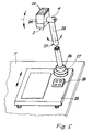
- the 5 has a stand ST which is formed by a tube 25 rotatable about its axis.
- One joint 26 sits, for example, in the base 27 of the stand, a second joint 4 at its upper end.
- the axis of rotation of this second joint 4 is directed horizontally and is perpendicular to that of the other joint 26.
- the axis of the objective 2 of the object camera OK is in turn oriented perpendicular to the axis of rotation of the joint 4 to which it is attached. This means that the object camera OK can be aimed at almost any point in the room.
- the housing 24 of the object camera is essentially cuboid.
- the base 27 of the stand ST can be designed as required so that it is free or that it can be attached to a table surface. In the transportable embodiment shown, it is fastened on a plate-shaped foot 23, on which control elements 28 can also be attached and which also forms the document support.
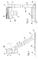
- FIG. 6 to 8 show a further embodiment of an object camera OK with a stand ST which is telescopically adjustable in height and has a pivotable arm 31.
- the arm 31 is fastened at one end to a joint 4 which can be rotated about a horizontal axis and which is seated on two parallel, tubular stator bars 32.
- the uprights 32 each consist of two tubes sliding into each other, which can be locked with the help of clamping screws 35, which each pass through a slot 36 in the outer tube and are screwed into the inner (Fig. 7).
- the length of the slots 36 determines the height of the stand ST.
- the uprights 32 stand on a flat, plate-shaped foot 33, which can be slid on a footprint (table) T under an image display device B, which is indicated by dash-dotted lines, in such a way that the object camera OK is aimed at a user above the screen.
- a second joint 34 is attached, the axis of rotation of which is perpendicular to that of the other joint 4.
- the object camera OK can theoretically be pivoted through 360 °, the axis of the objective 2 moving in a plane perpendicular to the axis of rotation of the joint 34.
- the locking in the desired position is again done using the tensioning screw 37.
- Usual knurled or toggle screws can be used as tensioning screws.
- the object camera OK can be attached to the head of the joint 34 in the same way.
- a second end position is drawn in dash-dot lines, in which the object camera OK is directed downward onto the table T for receiving documents or the like.
- the object camera is both around the joint 4 and also pivoted about the joint 34.
- the movement possibilities are indicated in FIGS. 6 to 8 by directional arrows.
Landscapes
- Engineering & Computer Science (AREA)
- General Engineering & Computer Science (AREA)
- Mechanical Engineering (AREA)
- Multimedia (AREA)
- Signal Processing (AREA)
- Accessories Of Cameras (AREA)
Applications Claiming Priority (2)
| Application Number | Priority Date | Filing Date | Title |
|---|---|---|---|
| DE9013986U DE9013986U1 (de) | 1990-10-08 | 1990-10-08 | Elektronische Objektkamera |
| DE9013986U | 1990-10-08 |
Publications (3)
| Publication Number | Publication Date |
|---|---|
| EP0480232A2 true EP0480232A2 (fr) | 1992-04-15 |
| EP0480232A3 EP0480232A3 (en) | 1993-10-27 |
| EP0480232B1 EP0480232B1 (fr) | 1996-01-17 |
Family
ID=6858171
Family Applications (1)
| Application Number | Title | Priority Date | Filing Date |
|---|---|---|---|
| EP91116203A Expired - Lifetime EP0480232B1 (fr) | 1990-10-08 | 1991-09-24 | Caméra électronique |
Country Status (2)
| Country | Link |
|---|---|
| EP (1) | EP0480232B1 (fr) |
| DE (2) | DE9013986U1 (fr) |
Cited By (5)
| Publication number | Priority date | Publication date | Assignee | Title |
|---|---|---|---|---|
| EP0524474A3 (en) * | 1991-07-26 | 1993-03-17 | Alcatel Sel Aktiengesellschaft | Picturephone |
| EP0560028A1 (fr) * | 1992-03-05 | 1993-09-15 | Usm U. Schaerer Soehne Ag | Table de vidéophare conférence pour participant |
| EP0749037A3 (fr) * | 1995-06-14 | 1999-06-23 | Canon Kabushiki Kaisha | Appareil pour enregistrer des images ayant des moyens pour régler et indiquer l'orientation d'une tête de caméra |
| WO2003076843A1 (fr) * | 2002-03-08 | 2003-09-18 | Wolfvision Gmbh | Bras articule, en particulier pour un appareil destine a la prise de vues optique d'objets |
| US7091961B2 (en) | 1993-06-29 | 2006-08-15 | Ditzik Richard J | Desktop device with adjustable flat screen display |
Families Citing this family (3)
| Publication number | Priority date | Publication date | Assignee | Title |
|---|---|---|---|---|
| DE9013986U1 (de) * | 1990-10-08 | 1990-12-13 | Alcatel Sel Ag, 70435 Stuttgart | Elektronische Objektkamera |
| DE9205664U1 (de) * | 1992-04-27 | 1992-07-23 | Alcatel Sel Ag, 70435 Stuttgart | Elektronische Objektkamera |
| FR2725805B1 (fr) * | 1994-10-18 | 1996-12-20 | Alcatel Business Systems | Appareil, a ecran et camera, dote d'un mecanisme d'orientation d'objectif |
Family Cites Families (6)
| Publication number | Priority date | Publication date | Assignee | Title |
|---|---|---|---|---|
| US3089028A (en) * | 1961-03-23 | 1963-05-07 | Golda G Klampferer | Stand with adjustably mounted head |
| FR2382140A1 (fr) * | 1977-02-25 | 1978-09-22 | Lartigue Alain | Dispositif de prise de vue video, noir ou couleur |
| US4258387A (en) * | 1979-10-17 | 1981-03-24 | Lemelson Jerome H | Video telephone |
| DE8902287U1 (de) * | 1989-02-27 | 1989-04-20 | Telenorma Telefonbau und Normalzeit GmbH, 6000 Frankfurt | Endgerät für Bildkommunikation |
| DE9013986U1 (de) * | 1990-10-08 | 1990-12-13 | Alcatel Sel Ag, 70435 Stuttgart | Elektronische Objektkamera |
| DE9110664U1 (de) * | 1991-08-29 | 1991-11-14 | Alcatel Sel Ag, 70435 Stuttgart | Elektronische Objektkamera |
-
1990
- 1990-10-08 DE DE9013986U patent/DE9013986U1/de not_active Expired - Lifetime
-
1991
- 1991-09-24 DE DE59107280T patent/DE59107280D1/de not_active Expired - Fee Related
- 1991-09-24 EP EP91116203A patent/EP0480232B1/fr not_active Expired - Lifetime
Cited By (8)
| Publication number | Priority date | Publication date | Assignee | Title |
|---|---|---|---|---|
| EP0524474A3 (en) * | 1991-07-26 | 1993-03-17 | Alcatel Sel Aktiengesellschaft | Picturephone |
| EP0560028A1 (fr) * | 1992-03-05 | 1993-09-15 | Usm U. Schaerer Soehne Ag | Table de vidéophare conférence pour participant |
| US7091961B2 (en) | 1993-06-29 | 2006-08-15 | Ditzik Richard J | Desktop device with adjustable flat screen display |
| EP0749037A3 (fr) * | 1995-06-14 | 1999-06-23 | Canon Kabushiki Kaisha | Appareil pour enregistrer des images ayant des moyens pour régler et indiquer l'orientation d'une tête de caméra |
| US6115068A (en) * | 1995-06-14 | 2000-09-05 | Canon Kabushiki Kaisha | Positionable image input apparatus |
| WO2003076843A1 (fr) * | 2002-03-08 | 2003-09-18 | Wolfvision Gmbh | Bras articule, en particulier pour un appareil destine a la prise de vues optique d'objets |
| US7104512B2 (en) | 2002-03-08 | 2006-09-12 | Wolfvision Gmbh | Articulated arm especially for a device for optically capturing objects |
| CN100417859C (zh) * | 2002-03-08 | 2008-09-10 | 沃福视讯股份有限公司 | 用于光学捕捉对象装置的铰接式臂状物 |
Also Published As
| Publication number | Publication date |
|---|---|
| DE59107280D1 (de) | 1996-02-29 |
| DE9013986U1 (de) | 1990-12-13 |
| EP0480232A3 (en) | 1993-10-27 |
| EP0480232B1 (fr) | 1996-01-17 |
Similar Documents
| Publication | Publication Date | Title |
|---|---|---|
| DE10044213C2 (de) | Vorrichtung für eine hängende Befestigung von Projektoren | |
| EP0480232B1 (fr) | Caméra électronique | |
| DE10208413A1 (de) | Schwenkbarer Stativkopf für eine Kamera | |
| DE10145197B4 (de) | Entkoppelter Gewichtsausgleich für eine Kamera-Balance-Vorrichtung | |
| DE3222954C2 (de) | Lichtschrankeneinheit | |
| WO2003010465A1 (fr) | Systeme d'equilibrage a poignee a roulement pour cameras portatives | |
| DE9407862U1 (de) | Stativeinrichtung | |
| DE10145198C1 (de) | Kardanische Aufhängevorrichtung für eine Kamera-Balance-Vorrichtung | |
| EP0019243B1 (fr) | Pied pour écrans de projection | |
| WO2003023272A1 (fr) | Dispositif de suspension a cardan destine a un dispositif d'equilibrage de camera | |
| DE4212412C2 (de) | Vorrichtung zur höhenverstellbaren Anordung von Bürogeräten oder -möbelteilen | |
| EP0568857A1 (fr) | Caméra électronique | |
| DE202007005393U1 (de) | Schulterstativ für eine Fernseh- oder Filmkamera | |
| DE102014206209B4 (de) | Kamerakran | |
| DE9110664U1 (de) | Elektronische Objektkamera | |
| DE890421C (de) | Verlaengerungsgeraet fuer Stative bzw. Kugelgelenke | |
| DE1541163A1 (de) | Anordnung fuer Roentgendurchleuchtungen | |
| EP0213078A2 (fr) | Caméra à compartiment | |
| AT405123B (de) | Staffelei | |
| DE29916225U1 (de) | Kran mit einer Vorrichtung zur automatischen Veränderung des Anstellwinkels von Geräten | |
| DE20311038U1 (de) | Halterung für eine Kamera | |
| DE2838403C3 (de) | Kinoneigekopf für eine Kinokamera mit Geräteträger | |
| DE2128825A1 (de) | Stativ | |
| DE29602314U1 (de) | Gelenkkonsole für eine Gelenkarmmarkise | |
| CH545981A (fr) |
Legal Events
| Date | Code | Title | Description |
|---|---|---|---|
| PUAI | Public reference made under article 153(3) epc to a published international application that has entered the european phase |
Free format text: ORIGINAL CODE: 0009012 |
|
| AK | Designated contracting states |
Kind code of ref document: A2 Designated state(s): CH DE FR IT LI |
|
| RAP3 | Party data changed (applicant data changed or rights of an application transferred) |
Owner name: ALCATEL SEL AKTIENGESELLSCHAFT |
|
| PUAL | Search report despatched |
Free format text: ORIGINAL CODE: 0009013 |
|
| AK | Designated contracting states |
Kind code of ref document: A3 Designated state(s): CH DE FR IT LI |
|
| 17P | Request for examination filed |
Effective date: 19931217 |
|
| 17Q | First examination report despatched |
Effective date: 19940722 |
|
| GRAA | (expected) grant |
Free format text: ORIGINAL CODE: 0009210 |
|
| AK | Designated contracting states |
Kind code of ref document: B1 Designated state(s): CH DE FR IT LI |
|
| REF | Corresponds to: |
Ref document number: 59107280 Country of ref document: DE Date of ref document: 19960229 |
|
| ITF | It: translation for a ep patent filed | ||
| ET | Fr: translation filed | ||
| PLBE | No opposition filed within time limit |
Free format text: ORIGINAL CODE: 0009261 |
|
| STAA | Information on the status of an ep patent application or granted ep patent |
Free format text: STATUS: NO OPPOSITION FILED WITHIN TIME LIMIT |
|
| 26N | No opposition filed | ||
| PGFP | Annual fee paid to national office [announced via postgrant information from national office to epo] |
Ref country code: CH Payment date: 19990816 Year of fee payment: 9 |
|
| PGFP | Annual fee paid to national office [announced via postgrant information from national office to epo] |
Ref country code: FR Payment date: 19990817 Year of fee payment: 9 |
|
| PGFP | Annual fee paid to national office [announced via postgrant information from national office to epo] |
Ref country code: DE Payment date: 19990820 Year of fee payment: 9 |
|
| PG25 | Lapsed in a contracting state [announced via postgrant information from national office to epo] |
Ref country code: LI Free format text: LAPSE BECAUSE OF NON-PAYMENT OF DUE FEES Effective date: 20000930 Ref country code: CH Free format text: LAPSE BECAUSE OF NON-PAYMENT OF DUE FEES Effective date: 20000930 |
|
| PG25 | Lapsed in a contracting state [announced via postgrant information from national office to epo] |
Ref country code: FR Free format text: LAPSE BECAUSE OF NON-PAYMENT OF DUE FEES Effective date: 20010531 |
|
| PG25 | Lapsed in a contracting state [announced via postgrant information from national office to epo] |
Ref country code: DE Free format text: LAPSE BECAUSE OF NON-PAYMENT OF DUE FEES Effective date: 20010601 |
|
| REG | Reference to a national code |
Ref country code: FR Ref legal event code: ST |
|
| PG25 | Lapsed in a contracting state [announced via postgrant information from national office to epo] |
Ref country code: IT Free format text: LAPSE BECAUSE OF NON-PAYMENT OF DUE FEES Effective date: 20050924 |
|
| REG | Reference to a national code |
Ref country code: CH Ref legal event code: PL Ref country code: CH Ref legal event code: NV Representative=s name: JUERG ULRICH C/O ALCATEL STR AG Ref country code: CH Ref legal event code: EP |