EP0480253A2 - Device for transverse extension of retiform materials and in particular fibrillar polymeric film - Google Patents
Device for transverse extension of retiform materials and in particular fibrillar polymeric film Download PDFInfo
- Publication number
- EP0480253A2 EP0480253A2 EP91116408A EP91116408A EP0480253A2 EP 0480253 A2 EP0480253 A2 EP 0480253A2 EP 91116408 A EP91116408 A EP 91116408A EP 91116408 A EP91116408 A EP 91116408A EP 0480253 A2 EP0480253 A2 EP 0480253A2
- Authority
- EP
- European Patent Office
- Prior art keywords
- guide
- guides
- distance
- section
- accordance
- Prior art date
- Legal status (The legal status is an assumption and is not a legal conclusion. Google has not performed a legal analysis and makes no representation as to the accuracy of the status listed.)
- Withdrawn
Links
- 239000000463 material Substances 0.000 title claims abstract description 15
- 238000013459 approach Methods 0.000 claims description 20
- 230000008602 contraction Effects 0.000 claims description 17
- 230000003247 decreasing effect Effects 0.000 claims description 3
- 230000000750 progressive effect Effects 0.000 claims description 2
- 230000000284 resting effect Effects 0.000 claims 2
- 230000008878 coupling Effects 0.000 claims 1
- 238000010168 coupling process Methods 0.000 claims 1
- 238000005859 coupling reaction Methods 0.000 claims 1
- 238000000034 method Methods 0.000 abstract description 5
- 240000004752 Laburnum anagyroides Species 0.000 abstract 1
- 210000000080 chela (arthropods) Anatomy 0.000 description 9
- 239000004744 fabric Substances 0.000 description 6
- 230000006641 stabilisation Effects 0.000 description 4
- 238000011105 stabilization Methods 0.000 description 4
- 239000004753 textile Substances 0.000 description 4
- 239000004568 cement Substances 0.000 description 2
- 230000007423 decrease Effects 0.000 description 2
- 230000000694 effects Effects 0.000 description 2
- 238000005516 engineering process Methods 0.000 description 2
- 235000011837 pasties Nutrition 0.000 description 2
- 238000011282 treatment Methods 0.000 description 2
- 229910000831 Steel Inorganic materials 0.000 description 1
- 238000005452 bending Methods 0.000 description 1
- 206010061592 cardiac fibrillation Diseases 0.000 description 1
- 239000002131 composite material Substances 0.000 description 1
- 230000001595 contractor effect Effects 0.000 description 1
- 230000001627 detrimental effect Effects 0.000 description 1
- 238000010586 diagram Methods 0.000 description 1
- 238000001035 drying Methods 0.000 description 1
- 239000013013 elastic material Substances 0.000 description 1
- 230000002600 fibrillogenic effect Effects 0.000 description 1
- 239000012530 fluid Substances 0.000 description 1
- 238000005470 impregnation Methods 0.000 description 1
- 238000004519 manufacturing process Methods 0.000 description 1
- 239000000203 mixture Substances 0.000 description 1
- 238000012986 modification Methods 0.000 description 1
- 230000004048 modification Effects 0.000 description 1
- 230000003014 reinforcing effect Effects 0.000 description 1
- 230000035939 shock Effects 0.000 description 1
- 238000004513 sizing Methods 0.000 description 1
- 239000010959 steel Substances 0.000 description 1
Images


Classifications
-
- B—PERFORMING OPERATIONS; TRANSPORTING
- B29—WORKING OF PLASTICS; WORKING OF SUBSTANCES IN A PLASTIC STATE IN GENERAL
- B29C—SHAPING OR JOINING OF PLASTICS; SHAPING OF MATERIAL IN A PLASTIC STATE, NOT OTHERWISE PROVIDED FOR; AFTER-TREATMENT OF THE SHAPED PRODUCTS, e.g. REPAIRING
- B29C55/00—Shaping by stretching, e.g. drawing through a die; Apparatus therefor
- B29C55/02—Shaping by stretching, e.g. drawing through a die; Apparatus therefor of plates or sheets
- B29C55/04—Shaping by stretching, e.g. drawing through a die; Apparatus therefor of plates or sheets uniaxial, e.g. oblique
- B29C55/08—Shaping by stretching, e.g. drawing through a die; Apparatus therefor of plates or sheets uniaxial, e.g. oblique transverse to the direction of feed
-
- D—TEXTILES; PAPER
- D06—TREATMENT OF TEXTILES OR THE LIKE; LAUNDERING; FLEXIBLE MATERIALS NOT OTHERWISE PROVIDED FOR
- D06C—FINISHING, DRESSING, TENTERING OR STRETCHING TEXTILE FABRICS
- D06C3/00—Stretching, tentering or spreading textile fabrics; Producing elasticity in textile fabrics
- D06C3/02—Stretching, tentering or spreading textile fabrics; Producing elasticity in textile fabrics by endless chain or like apparatus
- D06C3/025—Driving or guiding means for stenter chains
-
- B—PERFORMING OPERATIONS; TRANSPORTING
- B29—WORKING OF PLASTICS; WORKING OF SUBSTANCES IN A PLASTIC STATE IN GENERAL
- B29L—INDEXING SCHEME ASSOCIATED WITH SUBCLASS B29C, RELATING TO PARTICULAR ARTICLES
- B29L2028/00—Nets or the like
Definitions
- the invention described here relates to a device for a machine for the opening of textile and/or polymeric materials subject longitudinal to contraction during their transverse extension as happens for example with fibrillar polymeric film.
- Said film has been long known and is employed among other things for reinforcing pasty matrices such as for example cement mixtures to obtain thin articles with high bending and shock resistance.
- Fibrillation of synthetic polymeric film is an operation which has been long known and consists of producing in the film, by means of nails, blades or other equivalent mechanical means, a plurality of substantially longitudinal slits. The film thus fibrillard is subsequently opened transversely to take on the retiform structure which allows for example impregnation thereof with pasty cement matrices and is stabilized in said open form.
- the opening can reach values of 10-20 times the original width of the film and the longitudinal contraction can consequently take on values on the order of 15-40% of the original length of the film. If this contraction were not compensated for there would occur in the film distorsions and tensions such as to cause its breakage during opening.
- Ramates machines of known type however allow limited transverse extension with values of approximately 1.2-1.5 times the original width, much less than those required by the fibrillar film and any limited longitudinal contraction is compensated for by reducing the speed of collection in relation to feed speed and over-feeding the fabric by means of waviness before its grasping by needles.
- the tubular fibrillar film is opened by passing said film over an expansion form. Compensation for longitudinal shrinking is obtained by collecting the open film at the outlet of the form with speed less than that at which it was fed at the beginning of its running on the form.
- the open tubular film is preferably cut and the two flat films thus obtained are kept open during the stabilization phase by grasping members which draw the film along the opening element, overcoming the friction between the film and the edges of the form and the elastic resistance of the film without any specific film-grasping elements present in said crucial section of the machine and this is a serious shortcoming because it is a source of film breakage.
- the process is limited to tubular film.
- the film-grasping elements here consist of rollers positioned with uniform spacing and which also act as translation elements for the product.
- the edges of the undulated film are grasped by the needles which hold uniform their spacing and speed of translation.
- the film waviness compensates for the longitudinal contraction as the film flattens with progressive opening.
- the pincers are connected rigidly to a pair of translating chains which draw the film into the following section with parallel guides where thermostabilization of the open form takes place.
- the device which is the object of the present invention overcomes the above shortcomings in a simple and effective manner since it employs as lateral grasping elements for the film the usual and tested systems long employed in textile technology such as clamps, pincers or needles running on divergent opening guides and drawn by translating chains but partially disengages their travel from that of the chains to permit said grasping elements to draw together in the direction opposite the direction of travel of the product during opening and to keep said distance reduced in the following section although still conducted by the translation chains.
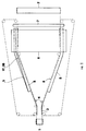
- FIG. 1 shows the general diagram of a machine for opening products subject to contraction in length during transverse extension such as for example the fibrillar polymeric films wherein the reciprocal approach of the grasping elements is accomplished with one of the devices shown in the following figures.
- FIG. 1 shows schematically or in blocks:
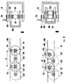
- FIGS. 2, 3, 4, 5 and 7 there are indicated by way of example three devices which permit the film-grasping elements (plates with pincers or needles) to draw together in a controlled manner even though they are still conducted by the divergent chains, accomplishing in the drawn film linear speeds lower than those of the chains.
- FIGS. 2B and 2C show a portion of a translation device 3 (FIG. 1) for fibrillar film consisting of a motorized roller chain 11 to which are connected in a nonrigid manner rigid rods of uniform length 12 on which are mounted the grasping elements 4 such as for example plates with needles 13 (FIG. 2A).
- a translation device 3 for fibrillar film consisting of a motorized roller chain 11 to which are connected in a nonrigid manner rigid rods of uniform length 12 on which are mounted the grasping elements 4 such as for example plates with needles 13 (FIG. 2A).
- the rods 12 can run in the sleeve 14 which connects them to the chain 11 but can also be inclined toward the chain thanks to the pin 15 fixed to the chain links.
- Inclination of the rods is caused by the variable and adjustable distance between the guides 17 and 8 on which the ends of the rods run by means of the rollers 19 and 20.
- the guide 8 delimits the field in which there moves the product drawn by the needles 13 and thus holds its position steady for each type of product and opening while the guide 17 has the possibility of varying its distance from the guide 8, forcing the rods 12 to incline in the direction of movement as shown in FIG. 2C.
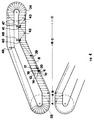
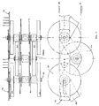
- FIGS. 3A, 3B and 7 show a second type of entraining device for the product in which 21 there is a chain whose links are united alternately by shafts 22 or 22bis which bear the pairs of wheels 24 or 23 respectively characterized by two different values of gauges, to wit the wheels 24 lie in planes outside those in which lie the gears 23.
- the chain can be of the drilled pin type through which pass alternately the shafts 22 or 22bis.
- the shafts 22 of the external gears 24, or the shafts 22bis, appropriately extended bear the grasping elements for the edges of the product represented in FIG. 3A by the needles 13.
- the grasping elements are free to rotate around an axis consisting of the idling shaft 22.
- the grasping elements 4, e.g. plates with needles 13, can as an alternative be fixed to plates 73 of FIG. 7 having at one end a circular hole and at the other end a hole with elongated shape mounted on the projecting ends of the shafts 22 as shown in FIG. 7 or the shafts 22bis appropriately lengthened and in this case the grasping elements are not oscillating and their trajectory during the opening phase of the fabric has more regular geometry.
- the two sets of gears 24 and 23 rest on the guides 8 and 26 respectively where the guide 26 is mobile in relation to the guide 8.
- a third device which permits drawing near of the grasping elements of the product is obtained by modifying the device described in FIGS. 2A 2B and 2C in such a manner that the translation elements 3, e.g. the roller chain 11, run over paths oblique to the path of the grasping elements, e.g. the needles 13, as shown in detail D of FIG. 2.
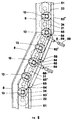
- FIG. 4 describes diagrammatically said third transverse extension device. There is indicated only one side of the device in which the section A-A is the section where the product is fed and is grasped on the edges by the grasping elements 4, the section B-B is the section where the product is extended transversely and the section C-C is the section where the extended product undergoes subsequent treatments such as for example thermostabilization.
- connection between the rods 12 and the chain 11 is provided by the sleeve 14 running along the rod 12 and free to rotate in relation to the chain 11.
- rollers 20 there are the grasping elements 4 consisting for example of a plate equipped with vertical needles 13.
- the guides 8 and 17 hold the spacing uniform during their travel while the chain 11 varies its distance from the guide 8.
- the product is detached from the needles 13 by a conventional device not shown, for example an appropriately positioned roller, and the chain, still bearing the rods 12, passes over the gears 34 and 35.
- Adjustment of the amount of approach of the needles 13 and hence of the contraction of the extensible product is carried out by moving transversely the snub pulleys 40 and 41 by means of the slides 46 and 47 while the gear 48 acts as a compensation means.
- Said strips are supported vertically by special bars connected together at the ends by articulated joints having their axis of rotation beneath the centre line of the above unbroken strips.
- the bars can move transversely by rotating on the joints and running on special slides placed on a supporting plate and moved by actuators such as for example pneumatic cylinders, moving screws, etc.
- the slides can rotate on a vertical pin, again under the centre line of the elastic strips, so as to cause the slide to follow the circular movement imposed by the rotation of the bars in the plane of the supporting plate.
- the bars united by the elastic strips and the articulated joints at the ends form a continuous guide for support of the rollers, in which the individual elements (the bars) can move transversely by rotating horizontally and forming a broken line in which however the zones of variation of direction are curved because of the elastic flexing of the unbroken strips.
- FIG. 5 shows examples of the above devices.
- FIG. 6 there is diagramed the assembly of four bars with continuous bucking guide applied to the device with the roller chain with drilled pins 21 with pitch variation illustrated in FIG. 3 and FIG. 7.
- 61 indicates the strip of elastic and flexible material which constitutes the guide 26 (FIG. 3) on which rest the internal wheels 23 of the roller chain with drilled pins 21, 8 indicates the fixed guide on which rest the external wheels 24, 62 indicates a rigid connection between the strip 61 and the guide bars 63, 64 indicates the articulated joints between the bars 63, 65 indicates the running slides of the guide bars 63, 66 indicates the rotation pins of the slides 65 which rotate in relation to the support plates 67, 68 indicates the movement actuators of the guides represented here as air cylinders, 69 indicates articulated connections between the actuators 63 and the supports 62 and finally 13 indicates the traction elements for the product and represented as needles.
- FIG. 6 which for graphic reasons is severely deformed in width, there are noted from below the bar 63' which bear the roller chain with drilled pins 21 in the straight inlet section of the film to be extended transversely without reciprocal approach of the guides 8 and of 26 (Fig. 3) and the needles 13, the following bar 63'' which begins the transverse extension section here also without reciprocal approach of the guides 8 and 26 and of the needles 13 because of the limited initial contraction of the film, the following bar 63''' which terminates the extension section and brings about reciprocal approach of the needles 13 and finally the bar 63'''' which constitutes the straight section with the product extended transversely, for which the movement actuator is not indicated and where reciprocal approach of the needles 13, accomplished by the previous section, is maintained.
Landscapes
- Engineering & Computer Science (AREA)
- Mechanical Engineering (AREA)
- Textile Engineering (AREA)
- Treatment Of Fiber Materials (AREA)
- Reinforced Plastic Materials (AREA)
- Shaping By String And By Release Of Stress In Plastics And The Like (AREA)
Abstract
Within the scope of a process of known type consisting of sending said retiform materials to transverse extension (opening) devices having elements (4) for grasping the product, e.g. needles (13), which run on opening elements, e.g. divergent guides, (8) and are towed by translation elements, e.g. chains, (3, 11, 21) the device in accordance with the present invention makes it possible to reduce in a controlled manner the distance between the product grasping elements (4) during the opening phase and subsequently maintain said reduced distance in such a manner that the translation speed of the material drawn by the grasping elements (4) can diminish progressively to compensate for the longitudinal retraction due to the transverse extension. <IMAGE>
Description
- The invention described here relates to a device for a machine for the opening of textile and/or polymeric materials subject longitudinal to contraction during their transverse extension as happens for example with fibrillar polymeric film.
- Said film has been long known and is employed among other things for reinforcing pasty matrices such as for example cement mixtures to obtain thin articles with high bending and shock resistance. Fibrillation of synthetic polymeric film is an operation which has been long known and consists of producing in the film, by means of nails, blades or other equivalent mechanical means, a plurality of substantially longitudinal slits. The film thus fibrillard is subsequently opened transversely to take on the retiform structure which allows for example impregnation thereof with pasty cement matrices and is stabilized in said open form.
- The opening can reach values of 10-20 times the original width of the film and the longitudinal contraction can consequently take on values on the order of 15-40% of the original length of the film. If this contraction were not compensated for there would occur in the film distorsions and tensions such as to cause its breakage during opening.
- Even in the field of treatment of fabric the transverse extension of textile materials is a long known conventional operation, in particular for light and deformable fabrics such as for example knitted fabrics, to stabilize the form thereof and is applied by conducting the fabric in divergent chain systems which carry rigidly constrained grasping elements for the edges of the film such as clamps, pincers or plates with needles, on machines termed rameuses or stenter frames where the open form is stabilized with hot air.
- Rameuses machines of known type however allow limited transverse extension with values of approximately 1.2-1.5 times the original width, much less than those required by the fibrillar film and any limited longitudinal contraction is compensated for by reducing the speed of collection in relation to feed speed and over-feeding the fabric by means of waviness before its grasping by needles.
- The operation of opening the fibrillar film is described in various patents.
- In European patent no. 0.011.371 the tubular fibrillar film is opened by passing said film over an expansion form. Compensation for longitudinal shrinking is obtained by collecting the open film at the outlet of the form with speed less than that at which it was fed at the beginning of its running on the form. The open tubular film is preferably cut and the two flat films thus obtained are kept open during the stabilization phase by grasping members which draw the film along the opening element, overcoming the friction between the film and the edges of the form and the elastic resistance of the film without any specific film-grasping elements present in said crucial section of the machine and this is a serious shortcoming because it is a source of film breakage. In addition the process is limited to tubular film.
- In European patent no. 0.009.294 the opening is obtained by conducting the edges of the film between two sets of roller pairs spaced apart and divergent progressively and having decreasing speeds.
- The film-grasping elements here consist of rollers positioned with uniform spacing and which also act as translation elements for the product.
- This process has the serious risk of detachment of the film from the grasping elements (the rollers) since grasping is entrusted only to the pressure of the rollers and the friction of the film. In European patent no. 075,306 the film is sent in wavy form obtained by thermal and mechanical operations to a conventional drying device or a textile thermostibilization device of the rameuse type consisting of divergent chains to which are rigidly constrained with uniform spacings the plates with needles drawn by the chain at uniform speed.
- The edges of the undulated film are grasped by the needles which hold uniform their spacing and speed of translation. The film waviness compensates for the longitudinal contraction as the film flattens with progressive opening.
- The shortcoming of this process is the fact that the thermal and mechanical effects necessary to obtain the waviness are detrimental to the mechanical characteristics of the product.
- In European patent no. 0.021.017 the fibrillar film is fed to an opening system made up of a pair of divergent guides. At the beginning of the divergent section the edges of the film are grasped by pincers which are inserted with uniform spacing in the guides and run there freely, drawn in the opening phase directly by the film and not by mechanical members of the machine.
- At the end of the divergent section and thus of the opening the pincers are connected rigidly to a pair of translating chains which draw the film into the following section with parallel guides where thermostabilization of the open form takes place.
- In this process the grasping elements (pincers) can draw near together during opening to compensate for longitudinal contraction, running on the divergent guides, but instead of drawing the film they are towed by it since in this section they are completely disengaged from the translation elements. This makes possible high tension and breakage of the film if the pincers should accidentally develop excessive friction in running on the divergent guides. Outline of the invention
- The device which is the object of the present invention overcomes the above shortcomings in a simple and effective manner since it employs as lateral grasping elements for the film the usual and tested systems long employed in textile technology such as clamps, pincers or needles running on divergent opening guides and drawn by translating chains but partially disengages their travel from that of the chains to permit said grasping elements to draw together in the direction opposite the direction of travel of the product during opening and to keep said distance reduced in the following section although still conducted by the translation chains.
- The reciprocal approach of the grasping elements in the opening phase and holding their distances in the following stabilization section cause the product to be drawn at the edges at a progressively decreasing speed such as to compensate for longitudinal contraction without being subject to thermal of harmful and undesirable mechanical stresses as takes place or can take place by adopting the known devices described above.
- The invention is better described with reference to some nonlimiting examples of embodiments illustrated in the annexed figures wherein:
- FIG. 1 shows schematically a machine of known type on which there can be mounted the device in accordance with the present invention,
- FIG. 2 shows a first example of embodiment of the present invention,
- FIG. 3 shows a second example of embodiment of the present invention,
- FIG. 4 shows further details of a third example of embodiment of the present invention as illustrated in FIG. 2D,
- FIGS. 5 and 6 show some details of a possible form of embodiment of the devices in accordance with the present invention illustrated in FIGS. 2, 3 and 4,
- FIG. 7 shows a further embodiment of the device shown in FIG. 3.
- FIG. 1 shows the general diagram of a machine for opening products subject to contraction in length during transverse extension such as for example the fibrillar polymeric films wherein the reciprocal approach of the grasping elements is accomplished with one of the devices shown in the following figures.
- FIG. 1 shows schematically or in blocks:
- the product to be opened 1 which can be made up of one or more overlaid layers fed by one or more spools or by production systems;
- the
open product 2 collected on spools with one or more layers; - translation elements 3, e.g. a pair of chains with rollers vertical thereto closed in a loop and on which there are the
grasping elements 4, e.g.plates with needles, for the edges of the product - the
opening elements 8 consisting of a pair of divergent guides in which run the chains 3 which can be arranged open and symmetrical (as shown in FIG. 1) or asymmetrical according to needs of the product to be opened; in particular one of theguides 8 can be nondivergent or have a divergence in relation to the central axis of the machine different from that of theother guide 8; - the
approach devices 5 for thegrasping elements 4 which permit compensation for the longitudinal contraction both in the opening section and in the following one where the speed of translation of the product is lower than the entry speed; the FIG. shows schematically on only one side of the machine the operation of themoving guides approach devices 5 do not affect the initial section of thedivergent guides 8 where the longitudinal contraction to be compensated for is negligible; - the
stabilization section 6 of the open form, which can be for example a hot-air oven for polymeric products, where there are optionally applied sizing, resining, cohesioning, etc.; thestabilization section 6 can take on forms and dimensions different from those diagramed in the FIG. 1 including for example part of the divergent section of theguide 8, without affecting the correct operation of the invention; and - a
release roller 7 for detaching the product from the needles. Where possible, in the subsequent FIGS. the same element is identified by the same reference number. - With reference to FIGS. 2, 3, 4, 5 and 7 there are indicated by way of example three devices which permit the film-grasping elements (plates with pincers or needles) to draw together in a controlled manner even though they are still conducted by the divergent chains, accomplishing in the drawn film linear speeds lower than those of the chains.
- FIGS. 2B and 2C show a portion of a translation device 3 (FIG. 1) for fibrillar film consisting of a motorized
roller chain 11 to which are connected in a nonrigid manner rigid rods ofuniform length 12 on which are mounted thegrasping elements 4 such as for example plates with needles 13 (FIG. 2A). - As indicated in FIG. 2 and in particular in FIG. 2A the
rods 12 can run in thesleeve 14 which connects them to thechain 11 but can also be inclined toward the chain thanks to thepin 15 fixed to the chain links. - Inclination of the rods takes place naturally in the direction of travel of the
needles 13 but astop 16 prevents inclination in the opposite direction. - Inclination of the rods is caused by the variable and adjustable distance between the
guides rollers - The
guide 8 delimits the field in which there moves the product drawn by theneedles 13 and thus holds its position steady for each type of product and opening while theguide 17 has the possibility of varying its distance from theguide 8, forcing therods 12 to incline in the direction of movement as shown in FIG. 2C. - As the inclination of the
rods 12 increases the pitch d' between theneedles 13 decreases and the speed of said needles decreases gradually to compensate for the longitudinal contraction due to the transverse extension. - FIGS. 3A, 3B and 7 show a second type of entraining device for the product in which 21 there is a chain whose links are united alternately by
shafts 22 or 22bis which bear the pairs ofwheels wheels 24 lie in planes outside those in which lie thegears 23. The chain can be of the drilled pin type through which pass alternately theshafts 22 or 22bis. Theshafts 22 of theexternal gears 24, or the shafts 22bis, appropriately extended bear the grasping elements for the edges of the product represented in FIG. 3A by theneedles 13. - In the case just described the grasping elements are free to rotate around an axis consisting of the idling
shaft 22. Thegrasping elements 4, e.g. plates withneedles 13, can as an alternative be fixed toplates 73 of FIG. 7 having at one end a circular hole and at the other end a hole with elongated shape mounted on the projecting ends of theshafts 22 as shown in FIG. 7 or the shafts 22bis appropriately lengthened and in this case the grasping elements are not oscillating and their trajectory during the opening phase of the fabric has more regular geometry. - The two sets of
gears guides guide 26 is mobile in relation to theguide 8. - When the
guide 26 approaches theguide 8 the links of the chain are forced to incline and thegears 24 approach each other, drawing near theneedles 13 and compensating for the longitudinal contraction of the product. - A third device which permits drawing near of the grasping elements of the product is obtained by modifying the device described in FIGS. 2A 2B and 2C in such a manner that the translation elements 3, e.g. the
roller chain 11, run over paths oblique to the path of the grasping elements, e.g. theneedles 13, as shown in detail D of FIG. 2. - If α is the angle between an oblique section of the
chain 11 having length d and p the corresponding path of theneedles 13, there will be p = d cos α where p < d. - FIG. 4 describes diagrammatically said third transverse extension device. There is indicated only one side of the device in which the section A-A is the section where the product is fed and is grasped on the edges by the
grasping elements 4, the section B-B is the section where the product is extended transversely and the section C-C is the section where the extended product undergoes subsequent treatments such as for example thermostabilization. - Considering the side of the device described here (the opposite side is only indicated in its initial section), there is noted the traction element indicated here by the
roller chain 11 which runs over a loop moved by a motor (not shown) by means of thegear 34. To thechain 11 are connected with uniform spacing therods 12 already described for FIG. 2A. - The connection between the
rods 12 and thechain 11 is provided by thesleeve 14 running along therod 12 and free to rotate in relation to thechain 11. - At the two ends the
rods 12 bear theroller systems guides - Above the
rollers 20 there are thegrasping elements 4 consisting for example of a plate equipped withvertical needles 13. - The
guides chain 11 varies its distance from theguide 8. - In the parallel section A-A and in part of the oblique section B-B the
chain 11 runs parallel to theguide 8 but in the last part of the oblique section B-B where the longitudinal contraction effect of the product begins to be considerable, it follows an oblique path thanks to the snub pulleys 39 and 40, thus forcing theneedles 13 to draw together. - In the following parallel section C-C diagramed only in its initial section, the
chain 11 follows the path shown by broken line thanks to the snub pulleys 40, 41, 42 and 43, forcing theneedles 13 to keep the close distance previously reached. - At the end of the section C-C the product is detached from the
needles 13 by a conventional device not shown, for example an appropriately positioned roller, and the chain, still bearing therods 12, passes over thegears - Adjustment of the amount of approach of the
needles 13 and hence of the contraction of the extensible product is carried out by moving transversely the snub pulleys 40 and 41 by means of theslides gear 48 acts as a compensation means. - In the devices indicated above the bucking guides (17 of FIGS. 2 and 4 and 26 of FIG. 3) and the
guides 8 must permit fluid running without forcing points of the rollers guided thereby, in particular where they change direction to bring about mutual approach of thegrasping elements 4, needles 13 or pincers. - This is secured by known technologies.
- By way of example, without limiting the principle of the invention, the purpose is achieved, (following for example British patent no. 1.080.915) by means of guides having the supporting surface of the rollers made of unbroken strips of a resistant, flexible and elastic material such as for example harmonic steel for springs or composite plastic material reinforced with fibres having a high elastic module.
- Said strips are supported vertically by special bars connected together at the ends by articulated joints having their axis of rotation beneath the centre line of the above unbroken strips.
- The bars can move transversely by rotating on the joints and running on special slides placed on a supporting plate and moved by actuators such as for example pneumatic cylinders, moving screws, etc.
- In turn the slides can rotate on a vertical pin, again under the centre line of the elastic strips, so as to cause the slide to follow the circular movement imposed by the rotation of the bars in the plane of the supporting plate.
- Therefore the bars united by the elastic strips and the articulated joints at the ends form a continuous guide for support of the rollers, in which the individual elements (the bars) can move transversely by rotating horizontally and forming a broken line in which however the zones of variation of direction are curved because of the elastic flexing of the unbroken strips.
- Moving of the bucking guides (indicated in the devices of FIGS. 2 and 4 by
reference number 17 and in the device of FIG. 3 and FIG. 7 by reference number 26) due to the effect of the actuators brings them close to the fixed guides 8. - Consequently there is inclination of the running
rods 12 of FIG. 2 or inclination of the links of thechain 21 of FIG. 3 and FIG. 7 and hence approach of the grasping elements for the product 4 (needles 13 or pincers). - Since the approach beween the guides increases progressively in the direction of movement of the product, the drawing near between the
grasping elements 4 also increases progressively as the transverse extension operation proceeds. - FIG. 5 shows examples of the above devices.
- In detail A there is diagramed the
continuous guide 61 which, in the device of FIG. 3, constitutes themobile guide 26 which bucks theinternal wheels 23 born by the roller chain with drilledpins 21 while in detail B the same continuous mobile guide system is applied to the device with running rods of FIG. 2. - In detail B there is noted the elastic and flexible
continuous strip 71 which corresponds to theguide 17 of FIG. 2, on which rest on both sides therollers 72 connected to one end of the runningrod 12, thesupports 62, theguide bar 63 with joint 64, theslides 65 with therotation pin 66 connected to thesupport plate 67 and finally the joint 69 which connects the guide to movingactuators 68 not shown in the figures. - In FIG. 6 there is diagramed the assembly of four bars with continuous bucking guide applied to the device with the roller chain with drilled
pins 21 with pitch variation illustrated in FIG. 3 and FIG. 7. - With reference to detail A of FIG. 5 and FIG. 6, 61 indicates the strip of elastic and flexible material which constitutes the guide 26 (FIG. 3) on which rest the
internal wheels 23 of the roller chain with drilledpins external wheels strip 61 and the guide bars 63, 64 indicates the articulated joints between thebars slides 65 which rotate in relation to thesupport plates actuators 63 and thesupports 62 and finally 13 indicates the traction elements for the product and represented as needles. - In particular FIG. 6, which for graphic reasons is severely deformed in width, there are noted from below the bar 63' which bear the roller chain with drilled
pins 21 in the straight inlet section of the film to be extended transversely without reciprocal approach of theguides 8 and of 26 (Fig. 3) and theneedles 13, the following bar 63'' which begins the transverse extension section here also without reciprocal approach of theguides needles 13 because of the limited initial contraction of the film, the following bar 63''' which terminates the extension section and brings about reciprocal approach of theneedles 13 and finally the bar 63'''' which constitutes the straight section with the product extended transversely, for which the movement actuator is not indicated and where reciprocal approach of theneedles 13, accomplished by the previous section, is maintained. - Without going beyond the scope of the invention it is possible for one skilled in the art to modify the mechanical devices described by way of example in FIGS. from 2 to 5 and 7 and use devices equivalent to those described above on the basis of his own experience and the natural evolution of the specific art.
- Finally, attention is drawn to the fact that the speed of translation of the means 3 and the amount of reciprocal movement of the
approach devices 5 associated with one of theguides 8 can be different from those of thecorresponding means 3 and 5 associated with theother guide 8. This allows using without appreciably modifications the above described devices even if one of theguides 8 is rectilinear or at least has a divergence angle different from that of theother guide 8.
Claims (10)
- Device for the transverse extension of retiform materials subject to contraction in length during transverse extension (widening), in particular fibrillar polymeric film, comprising two groups of members for lateral grasping of the product, said groups of grasping members being designed for running on a pair of guides which diverge at least for a section, in which there is effected widening of the material, followed by a parallel section in which the widened material is stabilized thermally or in some other known manner, characterized in that each group of grasping members (4) which run on one of said guides (8) is functionally connected to entraining means (3) having uniform motion and to which each grasping member (4) is connected at regular intervals and being guided by approach devices (5) designed for piloting along the section in which said guides (8) diverge the progressive reciprocal approach of two adjacent grasping members (4) to compensate for the contraction in length of the material during widening and also designed for maintaining the reduced distance thus achieved along the following parallel section of said guides (8).
- Device in accordance with claim 1 characterized in that said entraining means (3) comprise a roller chain (11) and each of said approach devices (5) comprises a rigid rod (12) having one end hinged to one of said grasping members (4) in turn constrained to run along said first guide (8) and the other end constrained to run along a second guide (17), said rod (12) being free to run in a sleeve (14) connected by a pin (15) to a roller of said chain (11).
- Device in accordance with claim 2 characterized in that:- the path of said roller chain (11) is parallel to that of the corresponding guide (8) and at the beginning of the divergent section of the first guides (8) the distance between said first guides (8) and the corresponding second guides (17) is equal to the length of said rods (12), said rods (12) being perpendicular to the first guide (8) and to the entraining means (11) and the distance (d) between two adjacent grasping members (4) being equal to the distance between the corresponding pins (15);- at least in the final part of the divergent section of said guides (8) the distance between each first guide (8) and the corresponding second guide (17) is progressively decreasing, forcing said rods (12), which run in the corresponding sleeve (14) and are free to rotate around the associated pin (15), to incline progressively in the direction of travel of the retiform material, thus reducing the distance (d') between the two adjacent grasping members (4) to compensate for the contraction in length of the retiform material due to the widening of said material;- in the following parallel section of said first guides (8) the distance between each first guide (8) and the corresponding second guide (17) is held uniform and equal to the distance between said guides (8,17) at the end of the preceding divergent section, forcing the rods (12) which are oblique and parallel to each other to maintain between two adjacent grasping members (4) the reduced distance (d') assumed at the end of the previous divergent section of the first guides (8).
- Device in accordance with claim 2 characterized in that said sleeve (14) comprises a stop (16) designed for preventing rotation around the associated pin (15) in a direction opposite that of travel of the retiform material.
- Device in accordance with claim 2 characterized in that the distance of at least one section of said second guides (17) from the corresponding section of said first guides (8) can be modified by means of slides or actuators (68).
- Device in accordance with claim 2 characterized in that the second guide (17) is parallel to the first guide (8), said rods (12) are parallel with each other and, at least in the final part of the divergent section and in the following parallel section of the first guides (8), the roller chain (11) follows an angled path created by a plurality of snub pulleys (39,42,43) which are fixed in relation to the first guide (8) and a plurality of snub pulleys (40,41) which are mobile in relation to said guide (8), thus varying its own distance from the first guide (8).
- Device in accordance with claim 6 characterized in that the positions of said mobile snub pulleys (40,41) can be modified by means of slides (46,47) or actuators (68).
- Device in accordance with claim 1 characterized in that said entraining means (3) and approach means (5) comprise a chain 21, preferably a roller chain with drilled pins and that on the shafts (22) and (22bis), passing through said pins, are keyed alternately a pair of idling wheels (24) resting on said first guide (8) or a pair of idling wheels (23) inside the wheels of said first pair (24) and resting on a second guide (26) which is mobile in relation to the corresponding first guide (8) and that, reducing the distance between the first guide (8) and the second guide (26) the links of the roller chain with pins (21) are forced to incline, reducing the distance between the two adjacent pairs of first wheels (24) and consequently between two adjacent grasping members (4), each of which is rigidly connected to a wheel (24) of said first pairs.
- Device in accordance with claim 8 characterized in that the grasping elements are born by plates (73) which connect only to the pins of the wheels (24) or (23), said plates being characterised by a normal circular hole for coupling to the pin of a wheel and an elongated hole which is used on the other pin to keep the alignment while allowing the pin running along the slot as a consequence of the pitch reduction.
- Device in accordance with claim 8 characterized in that the position of said second guide (26) in relation to said first guide (8) can be modified by means of slides (65) or actuators (68).
Applications Claiming Priority (2)
| Application Number | Priority Date | Filing Date | Title |
|---|---|---|---|
| IT02170890A IT1246460B (en) | 1990-10-11 | 1990-10-11 | P? ER DEVICE THE TRANSVERSAL EXTENSION OF RESISTIVE MATERIALS PARTICULARLY OF FIBRILLED POLYMER FILMS. |
| IT2170890 | 1990-10-11 |
Publications (2)
| Publication Number | Publication Date |
|---|---|
| EP0480253A2 true EP0480253A2 (en) | 1992-04-15 |
| EP0480253A3 EP0480253A3 (en) | 1993-05-05 |
Family
ID=11185739
Family Applications (1)
| Application Number | Title | Priority Date | Filing Date |
|---|---|---|---|
| EP19910116408 Withdrawn EP0480253A3 (en) | 1990-10-11 | 1991-09-26 | Device for transverse extension of retiform materials and in particular fibrillar polymeric film |
Country Status (4)
| Country | Link |
|---|---|
| EP (1) | EP0480253A3 (en) |
| JP (1) | JPH04281061A (en) |
| CA (1) | CA2052469A1 (en) |
| IT (1) | IT1246460B (en) |
Cited By (2)
| Publication number | Priority date | Publication date | Assignee | Title |
|---|---|---|---|---|
| EP0594982A1 (en) * | 1992-10-24 | 1994-05-04 | Lindauer Dornier Gesellschaft M.B.H | Fenter clip linkage |
| CN109968641A (en) * | 2017-11-20 | 2019-07-05 | 株式会社日本制钢所 | The transverse drawing mill for having longitudinal contractile function of tablet |
Families Citing this family (1)
| Publication number | Priority date | Publication date | Assignee | Title |
|---|---|---|---|---|
| JP7076142B2 (en) * | 2019-02-18 | 2022-05-27 | 株式会社市金工業社 | Telescopic chain and chain mechanism equipped with it |
Family Cites Families (5)
| Publication number | Priority date | Publication date | Assignee | Title |
|---|---|---|---|---|
| US2923966A (en) * | 1960-02-09 | Continuous biaxial stretching device | ||
| DE1234374B (en) * | 1961-03-21 | 1967-02-16 | Brueckner Trocknerbau Inh Gern | Device for biaxially stretching a material web in longitudinal and transverse directions |
| US3529332A (en) * | 1968-06-14 | 1970-09-22 | Bevis Ind Inc | Tenter frame |
| EP0149878B1 (en) * | 1984-01-24 | 1987-09-09 | Toray Industries, Inc. | Link device for stretching sheet material and stretching apparatus using said link device |
| DE3716603C1 (en) * | 1987-05-18 | 1989-03-09 | Dornier Gmbh Lindauer | Device for simultaneous biaxial treatment of film webs |
-
1990
- 1990-10-11 IT IT02170890A patent/IT1246460B/en active IP Right Grant
-
1991
- 1991-09-26 EP EP19910116408 patent/EP0480253A3/en not_active Withdrawn
- 1991-09-30 CA CA002052469A patent/CA2052469A1/en not_active Abandoned
- 1991-10-11 JP JP3292490A patent/JPH04281061A/en active Pending
Cited By (3)
| Publication number | Priority date | Publication date | Assignee | Title |
|---|---|---|---|---|
| EP0594982A1 (en) * | 1992-10-24 | 1994-05-04 | Lindauer Dornier Gesellschaft M.B.H | Fenter clip linkage |
| CN109968641A (en) * | 2017-11-20 | 2019-07-05 | 株式会社日本制钢所 | The transverse drawing mill for having longitudinal contractile function of tablet |
| CN109968641B (en) * | 2017-11-20 | 2021-03-30 | 株式会社日本制钢所 | Transverse stretcher with longitudinal contraction function of sheet-like object |
Also Published As
| Publication number | Publication date |
|---|---|
| CA2052469A1 (en) | 1992-04-12 |
| IT9021708A1 (en) | 1992-04-11 |
| JPH04281061A (en) | 1992-10-06 |
| IT9021708A0 (en) | 1990-10-11 |
| EP0480253A3 (en) | 1993-05-05 |
| IT1246460B (en) | 1994-11-18 |
Similar Documents
| Publication | Publication Date | Title |
|---|---|---|
| US3148409A (en) | Material treating machine | |
| US3551970A (en) | Apparatus for handling and processing open width fabric | |
| US5035030A (en) | Apparatus for controlling and straightening weft and/or warp fabric patterns | |
| US4172748A (en) | Method of forming non-woven net structures | |
| US2084367A (en) | Apparatus for treating cloth | |
| PL180280B1 (en) | Method of and apparatus for placing a braid on its substrate | |
| EP0480253A2 (en) | Device for transverse extension of retiform materials and in particular fibrillar polymeric film | |
| CH617730A5 (en) | ||
| US3228616A (en) | Apparatus for changing a helical winding angle | |
| US3973305A (en) | Apparatus for conditioning and calendering circular knit tubular fabrics | |
| US4174101A (en) | High speed horizontal folder | |
| US5442935A (en) | Apparatus for producing multi-axial non-woven fabric | |
| US3973304A (en) | Spreader for circular knit fabric tubes | |
| US6659138B2 (en) | Device for producing a tape having a curve, especially a curved flat line compound | |
| US3546044A (en) | Machine for making unwoven sheet material | |
| US3345232A (en) | Method and apparatus for making criss-cross material | |
| US3776541A (en) | Cloth folding machine | |
| US3973306A (en) | Method of orienting and calendering circular knit fabric tubes | |
| US4034702A (en) | Apparatus for manufacturing bias fabric | |
| US4097621A (en) | Method for manufacturing bias fabric | |
| US3095615A (en) | Plaiting apparatus | |
| RU2139378C1 (en) | Method and apparatus for drying and shrinkage of textile product | |
| CA2086666C (en) | Tenter for treatment of an endless fabric | |
| US9365976B2 (en) | Endless belt changing apparatus and method | |
| KR910002513B1 (en) | Compression shrinkage processing method and apparatus for circular knitted paper |
Legal Events
| Date | Code | Title | Description |
|---|---|---|---|
| PUAI | Public reference made under article 153(3) epc to a published international application that has entered the european phase |
Free format text: ORIGINAL CODE: 0009012 |
|
| AK | Designated contracting states |
Kind code of ref document: A2 Designated state(s): AT BE CH DE DK ES FR GB GR IT LI LU NL SE |
|
| PUAL | Search report despatched |
Free format text: ORIGINAL CODE: 0009013 |
|
| AK | Designated contracting states |
Kind code of ref document: A3 Designated state(s): AT BE CH DE DK ES FR GB GR IT LI LU NL SE |
|
| STAA | Information on the status of an ep patent application or granted ep patent |
Free format text: STATUS: THE APPLICATION IS DEEMED TO BE WITHDRAWN |
|
| 18D | Application deemed to be withdrawn |
Effective date: 19931106 |