EP0480277A2 - Support de cuvette moulé en mousse rigide pour cuvettes de baignoires ou de douche - Google Patents
Support de cuvette moulé en mousse rigide pour cuvettes de baignoires ou de douche Download PDFInfo
- Publication number
- EP0480277A2 EP0480277A2 EP91116650A EP91116650A EP0480277A2 EP 0480277 A2 EP0480277 A2 EP 0480277A2 EP 91116650 A EP91116650 A EP 91116650A EP 91116650 A EP91116650 A EP 91116650A EP 0480277 A2 EP0480277 A2 EP 0480277A2
- Authority
- EP
- European Patent Office
- Prior art keywords
- drain
- connection pipe
- tub
- recess
- drain connection
- Prior art date
- Legal status (The legal status is an assumption and is not a legal conclusion. Google has not performed a legal analysis and makes no representation as to the accuracy of the status listed.)
- Granted
Links
Images

Classifications
-
- A—HUMAN NECESSITIES
- A47—FURNITURE; DOMESTIC ARTICLES OR APPLIANCES; COFFEE MILLS; SPICE MILLS; SUCTION CLEANERS IN GENERAL
- A47K—SANITARY EQUIPMENT; ACCESSORIES THEREFOR, e.g. TOILET ACCESSORIES
- A47K3/00—Baths; Showers; Appurtenances therefor
- A47K3/16—Devices for fastening baths to floors or walls; Adjustable bath feet ; Lining panels or attachments therefor
- A47K3/1605—Hard foam bathtub supports
Definitions
- the invention relates to a molded foam tub support made of rigid foam for bathtubs or shower trays, consisting of a circumferential wall and a bottom, which merge into one another and form a trough for receiving the tub, the bottom having at least one recess for a tub drain.
- tub supports made of polystyrene foam or polyurethane foam have proven their worth. They can be installed quickly, are heat-insulating, soundproof and allow the tub to be replaced if necessary.
- At least one drain connection pipe is arranged in the wall of the tub support, the inlet end of which points towards the outer surface of the wall and the outlet end of which is directed into the recess below the level of the floor.
- the drain of a washing machine another device which dispenses hot water or a wash basin can be connected to the inlet end of such a drain connection pipe fitted in the tub support, be it via a hose or a pipe connection.
- the inlet end of the outlet connection pipe is designed either as a plug-in, screw or hose connection, as is customary in sanitary engineering using appropriate seals, such as elastic rubber sleeves or O-rings.
- the drain connection pipe is arranged in a prefabricated recess.
- such a recess can be formed directly in the molding tool by means of a corresponding insert piece or a slide.
- the drain connection pipe can either be used immediately by the manufacturer of the tub support or this only happens during assembly on the construction site.
- the second measure is always favorable if several recesses are provided for a drain connection pipe on the tub support, because in this case, taking into account the location of the sewage pipe on the building side, the required position of the recess in the tub support for receiving the drain fitting and the required placement of the washing machine can use the most conveniently located recess for inserting the drain connection pipe.
- the arrangement of several recesses in a tub support allows the storage of tub supports with special positioning of a single recess (for example at the head or foot end, at the Avoid right or left).
- the drain connection pipe can be fixed in the recess by gluing.
- the drain connection pipe is preferably fixed in the recess by a clamping bracket.
- the recess containing the drain connection pipe preferably has a cover aligned with the outer surface of the wall, and filler pieces are inserted into any other similar recesses.
- Such a cover or the filler pieces preferably also consist of foam and serve to fill the remaining space for stabilizing the tub support and as a support for the tiles with which the tub support is usually covered on the outside.
- the thickness of the seal is either matched to the thickness of the remaining space or the recess is provided with a circumferential recess in which the edge of the cover is fitted.
- the drain connection pipe is foamed.
- brackets such as, for example, spacers attached to the drain connection pipe or slide bolts engaging in the inlet and outlet ends of the connection drain pipe. Said spacers are foamed in and remain in the foam of the tub support.
- the drain connection pipe has a siphon or is designed as such.
- the inlet end of the drain connection pipe should preferably be above the maximum water level in the tub, i.e. at least at the level of the usual overflow on tubs.
- drain connection pipe has a simple shape, it can be manufactured as one piece. However, more complicated designs can be better identified from standard pipe sections, elbows, branches, siphons, valves, connections, especially those with plug connections, which are common in sanitary engineering, put together. No special creative activity is required for this.
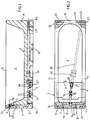
- the molded foam bath support consists of a peripheral wall 1, which merges into a floor 2.
- the trough 3 thus formed serves to accommodate a bathtub.
- a recess 4 is provided for receiving a drain fitting.
- At the foot end of the tub support is in the wall section 5 an outlet connecting pipe 6 is arranged. It is connected to the drain connection 7 of a tub overflow and has at the upper end cross tubes 8 and 9, of which the cross tube 8 has an inlet end 10 in the wall section 5 and an inlet end 11 in the wall section 12 and the cross tube 9 an inlet end 13 in the wall section 5 and a Has inlet end 14 in the wall section 15.
- the inlet ends that are not required can be sealed with sealing plugs.
- the lower end of the drain connection pipe 7 projects into the recess 4 and is designed as a siphon 16 with bellows sections 17. It goes without saying that the tub drain fitting must have a connection for the drain connection pipe 6 or the siphon 16.
- the drain connection pipe 6 is provided with spacers 18, which only have the task of holding the drain connection pipe 6 to be foamed in position in the mold cavity during foaming.
- An outlet connection pipe 20 is also provided in the wall section 19 of the bathtub support at the head. This has two inlet ends 21 and 22 and a branch 23 with two inlet ends 24 and 25.
- the inlet end 21 is in the wall section 12, the inlet ends 21 and 24 are in the wall section 19 and the inlet end 25 is provided in the wall section 15. Inlet ends that are not required can be closed with plugs.
- the drain connection pipe 20 is guided below the bottom 2. Since the inlet ends 21, 22, 24, 25 are also below the level of the bottom 2, a non-return valve 26 is arranged in the outlet connection pipe 20 so that when the bathing water runs out, it does not penetrate through the outlet connection pipe 20 into the connected washing machine.
- the drain end is also designed as a siphon 27 with bellows sections 28. However, it can also be connectable directly to the tub drain fitting or to the siphon 16 without a siphon 27. In this embodiment, it is expedient that the siphon 16 or 27 is only attached when the bathtub support is being installed, since there is generally only one need and therefore only one needs to be supplied, which is then connected to the corresponding drain connection pipe 6 or 20 is connected.
- Fig. 3 it is a shower tray support with peripheral wall 31 which merges into a floor 32, whereby a trough 33 is formed for receiving a shower tray.
- a trough 33 is formed for receiving a shower tray.
- the bottom 32 there is a recess 34 for the drain fitting intended.
- a commercially available, flat concealed siphon is foamed in as the outlet connecting pipe 36, the inlet end 37 of which opens in the wall section 35 to the outside.
- a hose connector 38 is inserted into the inlet end 37.
- the drain end 39 protrudes into the recess 34 and still requires a connecting piece for connection to the tub drain fitting equipped with a corresponding connection.
- the shower tray support also has a circumferential wall 41 which merges into a floor 42, so that a trough 43 is formed for receiving the shower tray.
- a recess 44 is provided in the bottom 42 for receiving a bath drain fitting.
- a tube cross 45 is foamed beneath the base 42, the ends of which extend into recesses 50, 51, 52 and 53 provided in the wall sections 46, 47, 48 and 49.
- a connecting arm 58 also leads from the tube cross 45 into the recess 44 in order to be able to connect this system to the bath drain fitting.
- the recesses 50, 51, 52 and 53 are designed for receiving a commercially available flush-mounted siphon 54 as a further part of the drain system, in such a way that undercuts 55 create a clamping effect.
- the siphon 54 has an inlet end 56 and an outlet end 57.
- the installer By arranging a recess 50, 51, 52 and 53 in each of the wall sections 46, 47, 48 and 49, the installer always has the option with regard to the position of the sewage pipes on the building side and the intended position of the washing machine, the siphon 54 in the to place the most conveniently located wall sections 46, 47, 48 or 49.
- the drain end 57 of the drain connection pipe or siphon 54 is designed such that it fits sealingly into each of the similar ends of the tube cross 45.
- the ends of the tube cross 45 that are not required can be closed by plugs. It also applies here that the assembly of the pipe system from suitable standard pieces is a purely professional measure.
- FIG. 7 shows a cover 71 for covering the siphon 54 shown in the recess 50 in FIG. 4. This cover 71 is pushed into the recess 50, possibly with gluing.
- FIGS. 4 to 6 shows a filling piece 81, of which three pieces are assigned to the tub support according to FIGS. 4 to 6, in order to fill those recesses 51, 52 and 53 in which no siphon 54 is arranged.
Landscapes
- Health & Medical Sciences (AREA)
- Public Health (AREA)
- Epidemiology (AREA)
- General Health & Medical Sciences (AREA)
- Sink And Installation For Waste Water (AREA)
- Blow-Moulding Or Thermoforming Of Plastics Or The Like (AREA)
- Casting Or Compression Moulding Of Plastics Or The Like (AREA)
- Domestic Plumbing Installations (AREA)
- Laminated Bodies (AREA)
- Bathtubs, Showers, And Their Attachments (AREA)
- Removal Of Water From Condensation And Defrosting (AREA)
- Bathtub Accessories (AREA)
Applications Claiming Priority (2)
| Application Number | Priority Date | Filing Date | Title |
|---|---|---|---|
| DE4032448 | 1990-10-12 | ||
| DE4032448A DE4032448C1 (fr) | 1990-10-12 | 1990-10-12 |
Publications (3)
| Publication Number | Publication Date |
|---|---|
| EP0480277A2 true EP0480277A2 (fr) | 1992-04-15 |
| EP0480277A3 EP0480277A3 (en) | 1992-10-14 |
| EP0480277B1 EP0480277B1 (fr) | 1995-04-26 |
Family
ID=6416175
Family Applications (1)
| Application Number | Title | Priority Date | Filing Date |
|---|---|---|---|
| EP91116650A Expired - Lifetime EP0480277B1 (fr) | 1990-10-12 | 1991-09-30 | Support de cuvette moulé en mousse rigide pour cuvettes de baignoires ou de douche |
Country Status (5)
| Country | Link |
|---|---|
| EP (1) | EP0480277B1 (fr) |
| AT (1) | ATE121604T1 (fr) |
| CZ (1) | CZ281140B6 (fr) |
| DE (2) | DE4032448C1 (fr) |
| PL (1) | PL167281B1 (fr) |
Families Citing this family (5)
| Publication number | Priority date | Publication date | Assignee | Title |
|---|---|---|---|---|
| US5283915A (en) * | 1992-08-10 | 1994-02-08 | Softub, Inc. | Power package for spa apparatus |
| DE9404786U1 (de) † | 1994-03-24 | 1995-04-20 | Königs, Wilfried, 47804 Krefeld | Formgeschäumter Bade-Duschwannenträger aus Kunststoff oder Hartschaum |
| DE10146812A1 (de) * | 2001-09-20 | 2003-04-24 | Mehdi Ghetmiri | Bodenbündiger Duschplatz |
| DE20311666U1 (de) * | 2003-07-28 | 2004-12-09 | Illbruck Gmbh | Duschbodenelement |
| DE102007051025A1 (de) * | 2007-10-25 | 2009-04-30 | Jung Pumpen Gmbh | Pumpschacht |
Family Cites Families (3)
| Publication number | Priority date | Publication date | Assignee | Title |
|---|---|---|---|---|
| US2395752A (en) * | 1944-01-24 | 1946-02-26 | Nuckey Percy | Baths combined or associated with lavatory basins |
| FR910066A (fr) * | 1945-03-30 | 1946-05-27 | Fabrication d'appareils sanitaires de luxe en marbre et métal | |
| IT1200377B (it) * | 1983-05-31 | 1989-01-18 | K & Q King Queen Spa | Base per l'appoggio e il sostegno di vasche da bagno,in particolare in materia plastica |
-
1990
- 1990-10-12 DE DE4032448A patent/DE4032448C1/de not_active Expired - Fee Related
-
1991
- 1991-09-30 AT AT91116650T patent/ATE121604T1/de not_active IP Right Cessation
- 1991-09-30 DE DE59105313T patent/DE59105313D1/de not_active Expired - Fee Related
- 1991-09-30 EP EP91116650A patent/EP0480277B1/fr not_active Expired - Lifetime
- 1991-10-11 CZ CS913099A patent/CZ281140B6/cs unknown
- 1991-10-11 PL PL91292004A patent/PL167281B1/pl unknown
Also Published As
| Publication number | Publication date |
|---|---|
| EP0480277A3 (en) | 1992-10-14 |
| CS309991A3 (en) | 1992-04-15 |
| DE59105313D1 (de) | 1995-06-01 |
| EP0480277B1 (fr) | 1995-04-26 |
| CZ281140B6 (cs) | 1996-06-12 |
| ATE121604T1 (de) | 1995-05-15 |
| DE4032448C1 (fr) | 1992-01-30 |
| PL292004A1 (en) | 1992-06-26 |
| PL167281B1 (pl) | 1995-08-31 |
Similar Documents
| Publication | Publication Date | Title |
|---|---|---|
| EP3527733A1 (fr) | Dispositif d'installation et procédé d'installation destinés à l'installation d'une évacuation d'une installation sanitaire | |
| EP1288379A1 (fr) | Bouche d'écoulement pour lavabo avec une sortie en forme de fente | |
| EP0480277B1 (fr) | Support de cuvette moulé en mousse rigide pour cuvettes de baignoires ou de douche | |
| DE202015006212U1 (de) | Ablaufanordnung | |
| DE102012102929B4 (de) | Sanitäranordnung | |
| DE3309460A1 (de) | Geschaeumter installationsbaustein fuer sanitaerapparate | |
| EP0436093A1 (fr) | Douche d'écoulement pour une cuve de douche | |
| DE102020004384A1 (de) | Bauschutz und Vorwandelement mit Bauschutz | |
| EP1046757B1 (fr) | Système de drainage pour blocs sanitaires | |
| AT11695U1 (de) | Vorrichtung zum anschliessen von wasserleitungen | |
| DE202008001013U1 (de) | Ablaufarmatur, insbesondere für Dusch- oder Badewannen | |
| EP1162907B1 (fr) | Procede pour l'installation d'un support de cuve et coque de cuve montee dans un tel support | |
| DE8507269U1 (de) | Vorrichtung zum Abstützen und Verkleiden von Sanitärbecken, insbesondere von Badewannen und Brausetassen | |
| DE202020003130U1 (de) | Bauschutz und Vorwandelement mit Bauschutz | |
| DE9014193U1 (de) | Formgeschäumter Wannenträger aus Hartschaumstoff für Bade- oder Duschwannen | |
| DE102018000146A1 (de) | Vorrichtung zum Ableiten von Abwasser | |
| DE69727166T2 (de) | Fertigelement für die wirksame Kupplung eines Installationsblocks an einem Flüssigkeitsver- und Entsorgungssystem | |
| DE2500337B2 (de) | Spüle für Haushalte | |
| DE2015328A1 (fr) | ||
| DE202004004277U1 (de) | Duschwanne | |
| DE560102C (de) | Vorrichtung zum Verhindern des Durchlaufens von Wasser zwischen Raumwand und dem Wannenrand | |
| AT382507B (de) | Vorrichtung zum abstuetzen und verkleiden von sanitaerbecken, insbesondere von badewannen und brausetassen | |
| DE617534C (de) | Wasserzu- und -ablaufeinrichtung fuer Waschbecken aus Steingut, Porzellan oder einem sonstigen keramischen oder aehnlichen Baustoff | |
| DE29823102U1 (de) | Wannenträger, insbesondere Badewannen- und Duschwannenträger | |
| DE7908435U1 (de) | Flachbrausetasse mit ablaufseitigem wassergeruchverschluss |
Legal Events
| Date | Code | Title | Description |
|---|---|---|---|
| PUAI | Public reference made under article 153(3) epc to a published international application that has entered the european phase |
Free format text: ORIGINAL CODE: 0009012 |
|
| AK | Designated contracting states |
Kind code of ref document: A2 Designated state(s): AT BE DE FR GB IT LU NL |
|
| PUAL | Search report despatched |
Free format text: ORIGINAL CODE: 0009013 |
|
| AK | Designated contracting states |
Kind code of ref document: A3 Designated state(s): AT BE DE FR GB IT LU NL |
|
| 17P | Request for examination filed |
Effective date: 19921106 |
|
| 17Q | First examination report despatched |
Effective date: 19940304 |
|
| GRAA | (expected) grant |
Free format text: ORIGINAL CODE: 0009210 |
|
| AK | Designated contracting states |
Kind code of ref document: B1 Designated state(s): AT BE DE FR GB IT LU NL |
|
| REF | Corresponds to: |
Ref document number: 121604 Country of ref document: AT Date of ref document: 19950515 Kind code of ref document: T |
|
| ET | Fr: translation filed | ||
| REF | Corresponds to: |
Ref document number: 59105313 Country of ref document: DE Date of ref document: 19950601 |
|
| GBT | Gb: translation of ep patent filed (gb section 77(6)(a)/1977) |
Effective date: 19950518 |
|
| ITF | It: translation for a ep patent filed | ||
| PLBE | No opposition filed within time limit |
Free format text: ORIGINAL CODE: 0009261 |
|
| STAA | Information on the status of an ep patent application or granted ep patent |
Free format text: STATUS: NO OPPOSITION FILED WITHIN TIME LIMIT |
|
| 26N | No opposition filed | ||
| PGFP | Annual fee paid to national office [announced via postgrant information from national office to epo] |
Ref country code: GB Payment date: 19960923 Year of fee payment: 6 |
|
| PGFP | Annual fee paid to national office [announced via postgrant information from national office to epo] |
Ref country code: FR Payment date: 19970718 Year of fee payment: 7 |
|
| PGFP | Annual fee paid to national office [announced via postgrant information from national office to epo] |
Ref country code: AT Payment date: 19970722 Year of fee payment: 7 |
|
| PG25 | Lapsed in a contracting state [announced via postgrant information from national office to epo] |
Ref country code: GB Free format text: LAPSE BECAUSE OF NON-PAYMENT OF DUE FEES Effective date: 19970930 |
|
| PGFP | Annual fee paid to national office [announced via postgrant information from national office to epo] |
Ref country code: NL Payment date: 19970930 Year of fee payment: 7 |
|
| PGFP | Annual fee paid to national office [announced via postgrant information from national office to epo] |
Ref country code: LU Payment date: 19971002 Year of fee payment: 7 |
|
| PGFP | Annual fee paid to national office [announced via postgrant information from national office to epo] |
Ref country code: BE Payment date: 19971118 Year of fee payment: 7 |
|
| GBPC | Gb: european patent ceased through non-payment of renewal fee |
Effective date: 19970930 |
|
| PG25 | Lapsed in a contracting state [announced via postgrant information from national office to epo] |
Ref country code: LU Free format text: LAPSE BECAUSE OF NON-PAYMENT OF DUE FEES Effective date: 19980930 Ref country code: BE Free format text: LAPSE BECAUSE OF NON-PAYMENT OF DUE FEES Effective date: 19980930 Ref country code: AT Free format text: LAPSE BECAUSE OF NON-PAYMENT OF DUE FEES Effective date: 19980930 |
|
| BERE | Be: lapsed |
Owner name: CORRECTA G.M.B.H. Effective date: 19980930 |
|
| PG25 | Lapsed in a contracting state [announced via postgrant information from national office to epo] |
Ref country code: NL Free format text: LAPSE BECAUSE OF NON-PAYMENT OF DUE FEES Effective date: 19990401 |
|
| PG25 | Lapsed in a contracting state [announced via postgrant information from national office to epo] |
Ref country code: FR Free format text: LAPSE BECAUSE OF NON-PAYMENT OF DUE FEES Effective date: 19990531 |
|
| NLV4 | Nl: lapsed or anulled due to non-payment of the annual fee |
Effective date: 19990401 |
|
| REG | Reference to a national code |
Ref country code: FR Ref legal event code: ST |
|
| PGFP | Annual fee paid to national office [announced via postgrant information from national office to epo] |
Ref country code: DE Payment date: 20021108 Year of fee payment: 12 |
|
| PG25 | Lapsed in a contracting state [announced via postgrant information from national office to epo] |
Ref country code: DE Free format text: LAPSE BECAUSE OF NON-PAYMENT OF DUE FEES Effective date: 20040401 |
|
| PG25 | Lapsed in a contracting state [announced via postgrant information from national office to epo] |
Ref country code: IT Free format text: LAPSE BECAUSE OF NON-PAYMENT OF DUE FEES;WARNING: LAPSES OF ITALIAN PATENTS WITH EFFECTIVE DATE BEFORE 2007 MAY HAVE OCCURRED AT ANY TIME BEFORE 2007. THE CORRECT EFFECTIVE DATE MAY BE DIFFERENT FROM THE ONE RECORDED. Effective date: 20050930 |