EP0480285A2 - Dispositif à rouleaux pour revêtement de bandes ou de feuilles - Google Patents
Dispositif à rouleaux pour revêtement de bandes ou de feuilles Download PDFInfo
- Publication number
- EP0480285A2 EP0480285A2 EP91116692A EP91116692A EP0480285A2 EP 0480285 A2 EP0480285 A2 EP 0480285A2 EP 91116692 A EP91116692 A EP 91116692A EP 91116692 A EP91116692 A EP 91116692A EP 0480285 A2 EP0480285 A2 EP 0480285A2
- Authority
- EP
- European Patent Office
- Prior art keywords
- roller
- counter
- applicator
- applicator according
- bearing
- Prior art date
- Legal status (The legal status is an assumption and is not a legal conclusion. Google has not performed a legal analysis and makes no representation as to the accuracy of the status listed.)
- Granted
Links
Images


Classifications
-
- B—PERFORMING OPERATIONS; TRANSPORTING
- B05—SPRAYING OR ATOMISING IN GENERAL; APPLYING FLUENT MATERIALS TO SURFACES, IN GENERAL
- B05C—APPARATUS FOR APPLYING FLUENT MATERIALS TO SURFACES, IN GENERAL
- B05C1/00—Apparatus in which liquid or other fluent material is applied to the surface of the work by contact with a member carrying the liquid or other fluent material, e.g. a porous member loaded with a liquid to be applied as a coating
- B05C1/04—Apparatus in which liquid or other fluent material is applied to the surface of the work by contact with a member carrying the liquid or other fluent material, e.g. a porous member loaded with a liquid to be applied as a coating for applying liquid or other fluent material to work of indefinite length
- B05C1/08—Apparatus in which liquid or other fluent material is applied to the surface of the work by contact with a member carrying the liquid or other fluent material, e.g. a porous member loaded with a liquid to be applied as a coating for applying liquid or other fluent material to work of indefinite length using a roller or other rotating member which contacts the work along a generating line
- B05C1/0826—Apparatus in which liquid or other fluent material is applied to the surface of the work by contact with a member carrying the liquid or other fluent material, e.g. a porous member loaded with a liquid to be applied as a coating for applying liquid or other fluent material to work of indefinite length using a roller or other rotating member which contacts the work along a generating line the work being a web or sheets
- B05C1/083—Apparatus in which liquid or other fluent material is applied to the surface of the work by contact with a member carrying the liquid or other fluent material, e.g. a porous member loaded with a liquid to be applied as a coating for applying liquid or other fluent material to work of indefinite length using a roller or other rotating member which contacts the work along a generating line the work being a web or sheets being passed between the coating roller and one or more backing rollers
Definitions
- roller application units with these features have been in use for a long time and are therefore generally known. Such devices have to meet certain conditions: The application roller and the counter roller must be completely rigid so that a uniform coating of the material passing through is guaranteed over the entire web width. This condition is met in the known applicators by appropriate dimensioning of the diameter and wall thickness of the applicator roller and the counter roller.
- the counter roller should not come into contact with the coating liquid. Their width must therefore be matched to the width of the sheet or sheet material to be coated. If the counter-roller protrudes laterally beyond the surface of the material to be coated, its edges are contaminated with the coating liquid, this contamination being transferred to subsequent rollers.
- the surface of the counter roll must have a more or less hard to soft elastic surface adapted to the coating substance. Since various types of sheet or sheet-like materials are to be coated with different substances with such an application unit, it is necessary that a number of counter-rollers with different surfaces on the one hand and different widths on the other hand be available. Of course, the counter roll must be interchangeably mounted in the applicator.
- the invention is therefore based on the object of improving a roller applicator of the type defined in the introduction to the description and in the preamble of claim 1 in such a way that the deficiencies described of the known applicator mechanisms of this type are eliminated.
- the counter roller should be light, be able to be kept available in a large number of designs with different surfaces and in different widths at the lowest possible cost, and be easy and quick to replace without great effort in manual work and technical aids.
- the accumulation wave of the coating liquid should be kept as short as possible before the inlet between the application roller and the material web to be coated, which improves the uniformity of the coating.
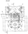
- a trough 3 for receiving a coating liquid is arranged in the lower region on a trough support 2 and a scoop roller 4 immersed in the trough 3 is mounted above it.
- the position of the tub support 2 is vertically adjustable by means of a hand spindle 5 .
- the tub 3 is easily removable on the tub support 2 and is exchangeably attached to another tub.
- the scoop roller 4 has a structured surface. It is associated with a doctor device 6 for wiping off excess coating liquid.
- the side walls 1 of the machine frame each have a vertical guide and bearing block 7 . In the lower region of a rolling on the scoop roller 4 application roller 8 is adjustably supported against the scoop roller.
- a counter-roller set is arranged above it, which is movable by means of several cylinder drives in the vertical guide of the guide and bearing blocks 7 against the application roller 8 .
- the counter-roller set consists of three rollers, namely two shape-identical, rigid press rollers 9 , 10 , which are mounted parallel and next to each other in a horizontal plane at a slightly greater distance above the applicator roller 8 and one between the applicator roller 8 and the two press rollers 9 , 10 counter roller 11 . This is pressed against the applicator roller 8 by the two press rollers 9 , 10 , whereby it rolls on the one hand under the press rollers 9 , 10 and on the other hand on the web 12 of the material to be coated which runs over the applicator roller 8 .
- the counter roll 11 is guided at both ends between the vertical bearing plates 13, which are each part of which is arranged on the guide blocks 7 mountings for the counter-roller. 11 It has a stub axle 14 with a central depression at each end. There is one end bearing ball 15 each, which rotates with the counter roller 11 on the adjacent bearing plate 13 of the holder.
- the brackets for the counter-roller 11 each consist of two movably connected parts, namely a bracket part 16 fastened to the adjacent guide and bearing block 7 and a device on the free inner side of which is rotatably mounted about an axis 17 running parallel to the counter-roller 11 at a distance from the latter for lateral guidance and for Lift the counter roller 11 out of its working position.
- Each of these at both ends of the counter roll 11 provided means for laterally guiding and lifting of the counter-roller 11 has a around the axis 17 pivotally mounted on Konsolteil 16, oriented perpendicular to the axis 17 of the bearing plate eighteenth
- Konsolteil 16 oriented perpendicular to the axis 17 of the bearing plate eighteenth
- two bearing journals 19 , 20 with commercially available ball bearings 19a , 20a are arranged, the axes of which are directed parallel to the counter roller 11 and on which these rests with their stub axles 14 .
- the bearing plate 18 is designed as a central part of a two-armed lever pivotable about the axis 17 .
- the short lever arm 21 is connected by a tension spring 22 to a downward arm 23 fastened to the bracket part 16 .
- the long lever arm opposite the short lever arm forms an operating lever 24 .
- the guide and bearing blocks 7 holding the counter-roller set 9 , 10 , 11 are vertically movable by means of a plurality of cylinder drives on the side walls 1 of the machine frame, whereby the counter-roller set 9 , 10 , 11 from the applicator roller 8 or from the web running over it 12 of the material to be coated can be lifted off. Then, after depressing the operating lever 24, the counter roller 11 can be easily removed and another one inserted.
- the counter roll 11 consists of a light core tube 11a , which is closed at both ends by end walls 11b with the stub axles 14 and is surrounded by a jacket 11c made of a different material.
- the coat 11c can, depending on the type the coating liquid and / or the material to be coated consist of more or less soft rubber, plastic or other material. Its surface can be smooth or textured. It can also be more or less shorter than the core tube 11a , its length depending on the width of the material web or sheet to be coated.
- the counter-roller 11 is practically not subjected to bending, since it bears under the rigid pressure rollers 9 , 10 over the entire length of its jacket 11c and is only pressed down by this onto the web of the material to be coated which runs over the application roller. It only has to withstand the pressure of the press rolls 9 , 10 without permanent deformation. Therefore, compared to the counter rolls in the known applicators, it can be built much more easily and, in terms of production costs, considerably cheaper. It is therefore much cheaper to have a larger range of counter-rollers with different surfaces and different shell widths. Due to the low weight, the replacement of the counter rollers can be carried out effortlessly with little manual work, even without technical aids.
Landscapes
- Coating Apparatus (AREA)
- Application Of Or Painting With Fluid Materials (AREA)
- Treatment Of Fiber Materials (AREA)
Applications Claiming Priority (2)
| Application Number | Priority Date | Filing Date | Title |
|---|---|---|---|
| DE4031946A DE4031946A1 (de) | 1990-10-09 | 1990-10-09 | Walzen-auftragwerk zum beschichten von durchlaufendem bahn- oder tafelfoermigem material |
| DE4031946 | 1990-10-09 |
Publications (3)
| Publication Number | Publication Date |
|---|---|
| EP0480285A2 true EP0480285A2 (fr) | 1992-04-15 |
| EP0480285A3 EP0480285A3 (en) | 1992-05-27 |
| EP0480285B1 EP0480285B1 (fr) | 1994-11-30 |
Family
ID=6415892
Family Applications (1)
| Application Number | Title | Priority Date | Filing Date |
|---|---|---|---|
| EP91116692A Expired - Lifetime EP0480285B1 (fr) | 1990-10-09 | 1991-09-30 | Dispositif à rouleaux pour revêtement de bandes ou de feuilles |
Country Status (3)
| Country | Link |
|---|---|
| EP (1) | EP0480285B1 (fr) |
| AT (1) | ATE114513T1 (fr) |
| DE (2) | DE4031946A1 (fr) |
Cited By (1)
| Publication number | Priority date | Publication date | Assignee | Title |
|---|---|---|---|---|
| CN105562283A (zh) * | 2016-02-15 | 2016-05-11 | 上海和科设备制造有限公司 | 一种扁管涂敷装置 |
Families Citing this family (1)
| Publication number | Priority date | Publication date | Assignee | Title |
|---|---|---|---|---|
| DE102019123050B4 (de) * | 2019-08-28 | 2021-03-18 | Achenbach Buschhütten GmbH & Co. KG | Auftragwerk |
Family Cites Families (2)
| Publication number | Priority date | Publication date | Assignee | Title |
|---|---|---|---|---|
| DE272473C (fr) * | ||||
| GB759138A (en) * | 1951-06-19 | 1956-10-17 | Nordisk Aluminium Ind As | Improved machine for the application of surface coating material to strips of metal or other solid material |
-
1990
- 1990-10-09 DE DE4031946A patent/DE4031946A1/de not_active Withdrawn
-
1991
- 1991-09-30 DE DE59103674T patent/DE59103674D1/de not_active Expired - Fee Related
- 1991-09-30 AT AT91116692T patent/ATE114513T1/de not_active IP Right Cessation
- 1991-09-30 EP EP91116692A patent/EP0480285B1/fr not_active Expired - Lifetime
Cited By (1)
| Publication number | Priority date | Publication date | Assignee | Title |
|---|---|---|---|---|
| CN105562283A (zh) * | 2016-02-15 | 2016-05-11 | 上海和科设备制造有限公司 | 一种扁管涂敷装置 |
Also Published As
| Publication number | Publication date |
|---|---|
| EP0480285B1 (fr) | 1994-11-30 |
| DE4031946A1 (de) | 1992-04-16 |
| EP0480285A3 (en) | 1992-05-27 |
| ATE114513T1 (de) | 1994-12-15 |
| DE59103674D1 (de) | 1995-01-12 |
Similar Documents
| Publication | Publication Date | Title |
|---|---|---|
| DE2605636A1 (de) | Verfahren und vorrichtung zur befeuchtung von bahnfoermigem material | |
| DE3017274C2 (de) | Vorrichtung zum Streichen von Papierbahnen | |
| EP0751256A2 (fr) | Ensemble de dosage | |
| DE2612373A1 (de) | Leiste mit metallueberzug und verfahren zu ihrer herstellung | |
| CH668922A5 (de) | Verfahren und vorrichtung fuer die streichbeschichtung einer sich bewegenden materialbahn. | |
| DE69614214T2 (de) | Reinigungsvorrichtung für Walzen | |
| DE3607108A1 (de) | Vorrichtung zum beidseitigen beschichten einer papierbahn | |
| EP0480285B1 (fr) | Dispositif à rouleaux pour revêtement de bandes ou de feuilles | |
| EP0901839B1 (fr) | Dispositif pour l'application de fluides sur un substrat | |
| DE2140612A1 (de) | Verfahren zur behandlung oder ausruestung von stoff und vorrichtung zur ausfuehrung des verfahrens | |
| DE10032500A1 (de) | Auftragsvorrichtung | |
| DE19941943A1 (de) | Verfahren und Vorrichtung zur Entnahme einer Reinigungsvorrichtung aus einer Druckmaschine | |
| EP0677613A2 (fr) | Dispositif pour déposer au moins un matériau fluide sur une bande en mouvement | |
| EP1808237B1 (fr) | Appareil de revêtement de bandes | |
| DE3750392T2 (de) | Verfahren zur Beschichtung von Siebdruckschablonen mit einem Schablonen-Emulsionsfilm. | |
| DE9014018U1 (de) | Walzen-Auftragwerk zum Beschichten von durchlaufendem bahn- oder tafelförmigem Material | |
| EP1621257B1 (fr) | Dispositif pour appliquer des segments d'un liquide sur une bande en mouvement | |
| CH629687A5 (de) | Vorrichtung zum auftragen einer beschichtungsfluessigkeit auf eine sich bewegende bahn. | |
| EP0757129A1 (fr) | Système d'application pour un appareil de revêtement d'une feuille de papier ou carton | |
| DE1671499B1 (de) | Verfahren und vorrichtung zum aufbringen eines negativen bildmusters auf einen zweilagigen siebdruckzylinder fuer den textildruck | |
| EP0177873B1 (fr) | Dispositif de pression et de l'enlèvement de rouleaux | |
| DE4021732C2 (de) | Vorrichtung zur Beschichtung eines Drucksiebes | |
| DE19603861C1 (de) | Vorrichtung zum Beschichten einer Materialbahn, insbesondere einer Papier- oder Kartonbahn | |
| EP1624106B1 (fr) | Dispositif d'enduction | |
| DE3715438A1 (de) | Einrichtung zum verbinden der enden von folienbahnen |
Legal Events
| Date | Code | Title | Description |
|---|---|---|---|
| PUAI | Public reference made under article 153(3) epc to a published international application that has entered the european phase |
Free format text: ORIGINAL CODE: 0009012 |
|
| PUAL | Search report despatched |
Free format text: ORIGINAL CODE: 0009013 |
|
| AK | Designated contracting states |
Kind code of ref document: A2 Designated state(s): AT BE CH DE ES FR GB IT LI NL SE |
|
| AK | Designated contracting states |
Kind code of ref document: A3 Designated state(s): AT BE CH DE ES FR GB IT LI NL SE |
|
| 17P | Request for examination filed |
Effective date: 19920715 |
|
| 17Q | First examination report despatched |
Effective date: 19940120 |
|
| GRAA | (expected) grant |
Free format text: ORIGINAL CODE: 0009210 |
|
| AK | Designated contracting states |
Kind code of ref document: B1 Designated state(s): AT BE CH DE ES FR GB IT LI NL SE |
|
| PG25 | Lapsed in a contracting state [announced via postgrant information from national office to epo] |
Ref country code: IT Free format text: LAPSE BECAUSE OF FAILURE TO SUBMIT A TRANSLATION OF THE DESCRIPTION OR TO PAY THE FEE WITHIN THE PRE;WARNING: LAPSES OF ITALIAN PATENTS WITH EFFECTIVE DATE BEFORE 2007 MAY HAVE OCCURRED AT ANY TIME BEFORE 2007. THE CORRECT EFFECTIVE DATE MAY BE DIFFERENT FROM THE ONE RECORDED.SCRIBED TIME-LIMIT Effective date: 19941130 Ref country code: ES Free format text: THE PATENT HAS BEEN ANNULLED BY A DECISION OF A NATIONAL AUTHORITY Effective date: 19941130 |
|
| REF | Corresponds to: |
Ref document number: 114513 Country of ref document: AT Date of ref document: 19941215 Kind code of ref document: T |
|
| REF | Corresponds to: |
Ref document number: 59103674 Country of ref document: DE Date of ref document: 19950112 |
|
| GBT | Gb: translation of ep patent filed (gb section 77(6)(a)/1977) |
Effective date: 19950123 |
|
| ET | Fr: translation filed | ||
| PG25 | Lapsed in a contracting state [announced via postgrant information from national office to epo] |
Ref country code: SE Effective date: 19950228 |
|
| PGFP | Annual fee paid to national office [announced via postgrant information from national office to epo] |
Ref country code: AT Payment date: 19950928 Year of fee payment: 5 |
|
| PLBE | No opposition filed within time limit |
Free format text: ORIGINAL CODE: 0009261 |
|
| STAA | Information on the status of an ep patent application or granted ep patent |
Free format text: STATUS: NO OPPOSITION FILED WITHIN TIME LIMIT |
|
| 26N | No opposition filed | ||
| PG25 | Lapsed in a contracting state [announced via postgrant information from national office to epo] |
Ref country code: AT Effective date: 19960930 |
|
| REG | Reference to a national code |
Ref country code: GB Ref legal event code: 732E |
|
| REG | Reference to a national code |
Ref country code: CH Ref legal event code: NV Representative=s name: KELLER & PARTNER PATENTANWAELTE AG Ref country code: CH Ref legal event code: PUE Owner name: DIPL.-ING. ERICH HANSSMANN TRANSFER- EHA SPEZIALMA |
|
| REG | Reference to a national code |
Ref country code: FR Ref legal event code: TP |
|
| PGFP | Annual fee paid to national office [announced via postgrant information from national office to epo] |
Ref country code: FR Payment date: 19990929 Year of fee payment: 9 Ref country code: GB Payment date: 19990929 Year of fee payment: 9 |
|
| PGFP | Annual fee paid to national office [announced via postgrant information from national office to epo] |
Ref country code: NL Payment date: 19990930 Year of fee payment: 9 |
|
| PGFP | Annual fee paid to national office [announced via postgrant information from national office to epo] |
Ref country code: BE Payment date: 19991011 Year of fee payment: 9 |
|
| PGFP | Annual fee paid to national office [announced via postgrant information from national office to epo] |
Ref country code: CH Payment date: 19991026 Year of fee payment: 9 |
|
| PG25 | Lapsed in a contracting state [announced via postgrant information from national office to epo] |
Ref country code: GB Free format text: LAPSE BECAUSE OF NON-PAYMENT OF DUE FEES Effective date: 20000930 Ref country code: CH Free format text: LAPSE BECAUSE OF NON-PAYMENT OF DUE FEES Effective date: 20000930 Ref country code: BE Free format text: LAPSE BECAUSE OF NON-PAYMENT OF DUE FEES Effective date: 20000930 Ref country code: LI Free format text: LAPSE BECAUSE OF NON-PAYMENT OF DUE FEES Effective date: 20000930 |
|
| BERE | Be: lapsed |
Owner name: EHA SPEZIALMASCHINENBAU G.M.B.H. Effective date: 20000930 |
|
| PG25 | Lapsed in a contracting state [announced via postgrant information from national office to epo] |
Ref country code: NL Free format text: LAPSE BECAUSE OF NON-PAYMENT OF DUE FEES Effective date: 20010401 |
|
| REG | Reference to a national code |
Ref country code: CH Ref legal event code: PL |
|
| GBPC | Gb: european patent ceased through non-payment of renewal fee |
Effective date: 20000930 |
|
| PG25 | Lapsed in a contracting state [announced via postgrant information from national office to epo] |
Ref country code: FR Free format text: LAPSE BECAUSE OF NON-PAYMENT OF DUE FEES Effective date: 20010531 |
|
| NLV4 | Nl: lapsed or anulled due to non-payment of the annual fee |
Effective date: 20010401 |
|
| REG | Reference to a national code |
Ref country code: FR Ref legal event code: ST |
|
| PGFP | Annual fee paid to national office [announced via postgrant information from national office to epo] |
Ref country code: DE Payment date: 20041019 Year of fee payment: 14 |
|
| PG25 | Lapsed in a contracting state [announced via postgrant information from national office to epo] |
Ref country code: DE Free format text: LAPSE BECAUSE OF NON-PAYMENT OF DUE FEES Effective date: 20060401 |